

Page 1
PC/104 Peripheral Module PCM-3660 Rev.B
Notice
This guide is designed for experienced users to setup the syste m in
the shortest time.
Safety Precautions
Always completely disconnect the power cord
from your board whenever you are working
on it. Do not make connections while the
power is on, because a sudden rush of power
can damage sensitive electronic
components.
Always ground yourself to remove any static
charge before touching the board. Modern
electronic devices are very sensitive to static
electric charges. Use a grounding wrist strap
at all times. Place all electronic components
on a static-dissipative surface or in a
static-shielded bag when they are not in the
chassis.
PCM-3660 Rev.B Quick Installation Guide
1-1
Page 2
PC/104 Peripheral Module PCM-3660 Rev.B
Introduction
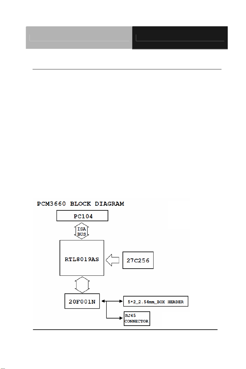
The PCM-3660 Rev.B is a high-performance 16-bit jumperless Ethernet
interface module that attaches to the PC/104 connector on your CPU card or
PC/104 CPU module. The module automatically senses whether it is
connected to an 8-bit or 16-bit PC/104 system. The PCM-3660 Rev.B fully
complies with IEEE 802.3 10 Mbps CSMA/CD standards and is 100%
Novell NE2000 compatible.
The module includes a built-in 10BASE-T transceiver and RJ-45 connector.
Two diagnostic LEDs indicate the operating The PCM-3660 Rev.B comes
with drivers for a wide variety of networks and operating systems. An
optional boot ROM lets you boot a remote PC/104 station automatically from
a server, making hard or floppy disks unnecessary.
PCM-3660 Rev.B Quick Installation Guide 1-2
Page 3

PC/104 Peripheral Module PCM-3660 Rev.B
Features
Conforms to IEEE 802.3 Ethernet standards, CSMA/ CD protocol for
10 Mbps data transfer
Hardware and software compatible with Novell NE2000 adapter
Automatically detects 8-bit or 1 6-bit data bus
Remote boot ROM socket for diskless operation
Built-in 10BASE-T transceiver for unshielded twisted pair cabling up to
100 meters
Two diagnostic LEDs indicate network status
Onboard 32K memory for high-performance multi-package buffer
Software drivers for most popular network environments
PCM-3660 Rev.B Quick Installation Guide 1-3
Page 4

PC/104 Peripheral Module PCM-3660 Rev.B
Specification
Hardware
Form Factor
I/O address
Interrupt levels
Boot ROM address
Data bus
Connectors
Dimension
Software
Driver Support
PC/104
200, 220, 240, 260, 280, 2A0, 2C0, 300,
320, 340, 380 or 3A0
IRQ3, 4, 5, 9, 10, 11, or 15
C0000, C8000, D0C00 or D8000H
8-bit or 16-bit, auto-sensing
16-bit PC/104 stack through connector
RJ-45 connector for 10BASE-T, 16-pin
insulation displacement connector for AUI
3.5” x 3.8” (90mm x 96 mm )
-Lantasti 4.x/5.xdriver
-NDIS 2.x driver
-Packet driver
-SCO UNIX driver
-Netware ODI driver
-NDIS 3.0 miniport driver for Windows NT
31, Windows NT 35 and Windows 95
-OS2driver
PCM-3660 Rev.B Quick Installation Guide 1-4
Page 5

PC/104 Peripheral Module PCM-3660 Rev.B
-Netware serverdriver
Standard
PC/104 8-bit and 16-bit compatible
Built in IEEE 802.3 10 Mbps CSMA/CD 10BASE-T transceiver
10BASE-2, 10BASE-5 and 10BASE-FOIRL by external transceiver
General
Power
Operating
Temperature
Storage
Temperature
Humidity
+5 V 400 mA max.
32°F~140°F (0°C ~ 60°C)
5°F~176°F (-15°C ~ 80°C)
10% ~ 90%
PCM-3660 Rev.B Quick Installation Guide 1-5
Page 6

PC/104 Peripheral Module PCM-3660 Rev.B
Installation
Your package should contain the following items. If they are missing,
damaged or fail to meet specifications, contact your dealer/sales
representative immediately.
PCM-3660 Rev.B
Drivers
PCM-3660 Rev.B Quick Installation Guide 1-6
Page 7

PC/104 Peripheral Module PCM-3660 Rev.B
Software Configuration
The PCM-3660 Rev. B module is supplied with a software utility disk.
This disk contains the files necessary for setting up the Ethernet
controller. Directories and files on the disk are as follows:
1. RSET8019.EXE
This program enables you to view the current Ethernet configuration,
reconfigure the Ethernet interface (medium type, etc.), and execute
useful diagnostic functions.
2. PG8019.EXE
The PCM-3660 is initially set up at the factory using this program.
When you receive your card, use RSET8019.EXE to configure it for
the working environment. If by chance the EEPROM becomes
corrupted, the PG8019.EXE program allows you to reconfigure the
card.
3. 8019AS.CFG
n you run PG801 9.EXE, it will read the configuration
Whe
parameters stored in this file.
PCM-3660 Rev.B Quick Installation Guide 1-7
Page 8

PC/104 Peripheral Module PCM-3660 Rev.B
Ethernet Interface Configuration
The PCM-3660 Rev.B onboard Ethernet interface supports all major
network operating systems. I/O address and interrupts are easily
configured via the RSET801 9.EXE program included on the utility
disk.
The RSET8019.EXE program provides two ways to configure the
Ethernet interface. Configuration can be done automatically when
you choose PNP (plug and play). When you choose jumperless
configuration, the following IRQ and I/O address settings are
available.
Ethernet Settings
Default Settings: IRO=5; Address=300H
IR0 option I/O address range
Jumperless
3, 4, 5, 9,10, 11,15 200-3FFH
Configuration
Note:
1. You can select an IRQ from the Options shown above, but be sure that
your selection does not conflict with other l/O devices.
2. When Boot ROM is installed, the RSET8019.EXEprogram does not
support PNP mode configuration.
To execute the configuration, to see the current configuration, or run
diagnostics as followings:
1. Power the PCM-3660 Rev.B on. Make sure that the
RSET8019.EXE file is located in a working directory.
PCM-3660 Rev.B Quick Installation Guide 1-8
Page 9

PC/104 Peripheral Module PCM-3660 Rev.B
2. At the prompt type RSET8019.exe and press <Enter>. Then the
Ethernet configuration program will be displayed.
3. A simple screen displays the available options for the Ethernet
interface. Highlight the option you are going to change and using the
Up and Down keys. To change a selected item press <Enter>, and a
window will show the available options. Highlight your selection and
press <Enter>. Each highlighted option has a helpful message guide
displayed at the bottom of the screen for additional information.
4. After you have made your selections and you are sure that this is
the configuration you want, press <ESC>. A prompt will appear
asking if you want to save the configuration. Press Y if you want to
save.
The Ethernet Setup Menu also offers three very useful diagnostic
functions. These are:
1. Run EEPROM test.
2. Run Diagnostics on Board.
3. Run Diagnostics on Network
Each option has its own display screen which shows the format and
result of any diagnostic tests undertaken.
Remote boot ROM (P/N: PCL-843-ROM)
PCM-3660 Rev.B Quick Installation Guide 1-9
Page 10

PC/104 Peripheral Module PCM-3660 Rev.B
A boot ROM allows you to boot the wo
rkstation directly from the
server, avoiding the need for local hard or floppy disks. Install the
boot ROM as shown below. Make sure that you align the notch on
the ROM chip with the notch on the socket.
PCM-3660 Rev.B Quick Installation Guide 1-10
Page 11

PC/104 Peripheral Module PCM-3660 Rev.B
Hardware Installation
The following instructions show how to install the PCM-3660 Rev.B
module on a CPU card. The process is similar to PC/104 CPU
modules’ and see the figures.
Make sure that you have properly configured the module’s jumpers
and attached a boot ROM if necessary.
Warning!
TURN OFF your PC power supply whenever you install or remove the
PCM-3660 Rev.B or connect and disconnect cables.
1. Turn off the power of the PC. Turn off the power of any peripheral
devices, such as printers and monitors.
2. Disconnect the power cord and any other cables from the back of
the computer.
3. Remove the cover of the system unit (see the user’s guide for
your chassis if necessary)
4. Remove the CPU card from the chassis (if necessary) and access
the card’s PC/104 connector.
5. Screw the brass spacer (included with the module) into the
threaded hole on the CPU card. Do not tighten too much, or the
threads may be damaged.
6. Carefully align the connector pins of the PCM-3660 Rev.B
(PC104AB1 and PC104CD1) with the PC/104 connector. Slide the
module into the connector. The module pins may not slide all the
PCM-3660 Rev.B Quick Installation Guide 1-11
Page 12

PC/104 Peripheral Module PCM-3660 Rev.B
way into the connector; Do not push too hard or the module may be
damag
ed. If the CPU card has only an 8-bit bus, make sure that the
pins on connector PC104CD1 do not touch anything.
7. Secure the module to the CPU card to the threaded hole in the
CPU card using the included screw.
8. Reinstall the CPU card and system unit cover. Reconnect the
cables you removed in step 2. Turn on the power.
This completes the hardware installation. Install the software drivers
according to the instructions of your operating system.
PCM-3660 Rev.B Quick Installation Guide 1-12
Page 13

PC/104 Peripheral Module PCM-3660 Rev.B
Ethernet Connection Specifications
The following table shows the network specifications for each
Ethernet.
Ethernet
Data
Topology Cable Type Segment
Type
10 Base-2 10 Mbps Bus 50 Ohm Ethernet
10 Base-5 10 Mbps Bus 50 Ohm Ethernet
10 Base-T 10 Mbps Star 100 Ohm
transfer
rate
thin (RG-58)
thin (RG-11)
unshielded twisty
pair
Pin Assignment (CN2)
Length
185m (607 ft.)
max.
500m (1640 ft.)
max.
100m (328 ft.)
max.
PCM-3660 Rev.B Quick Installation Guide 1-13
Page 14

PC/104 Peripheral Module PCM-3660 Rev.B
RJ-45 Connector (RJ1)
Pin Signal Description
1 TD+ Data transmission positive
2 TD- Data transmission negative
3 RD+ Data reception positive
6 RD- Data reception negative
LCD Indicators
The module’s two LED indicators show the status of the
communication link and traffic.
LED On Flashing Off
LED2
LED3 Link OK
RJ-45 Pin assignments
PCM-3660 Rev.B Quick Installation Guide 1-14
-
Traffic No traffic
-
Link failure
 Loading...