

Page 1

Industrial Motherboard
IMBM-H61B
Page 2

ii
E7930
First Edition (V1)
January 2013
Copyright Notice
This document is copyrighted, 2013. All rights are reserved. The original
manufacturer reserves the right to make improvements to the products described
in this manual at any time without notice.
No part of this manual may be reproduced, copied, translated, or transmitted
in any form or by any means without the prior written permission of the original
manufacturer. Information provided in this manual is intended to be accurate and
reliable. However, the original manufacturer assumes no responsibility for its use,
or for any infringements upon the rights of third parties that may result from its use.
The material in this document is for product information only and is subject to
change without notice. While reasonable efforts have been made in the preparation
of this document to assure its accuracy, the original manufacturer assumes no
liabilities resulting from errors or omissions in this document, or from the use of the
information contained herein.
The original manufacturer reserves the right to make changes in the product
design without notice to its users.
Acknowledgments
All other products’ name or trademarks are properties of their respective owners.
AMI is a trademark of American Megatrends Inc.
Intel®, Core™ are trademarks of Intel® Corporation.
Microsoft Windows® is a registered trademark of Microsoft Corp.
ITE is a trademark of Integrated Technology Express, Inc.
IBM, PC/AT, PS/2, and VGA are trademarks of International Business
Machines Corporation.
The original manufacturer reserves the right to make changes in the product
design without notice to its users.
All other product names or trademarks are properties of their respective owners.
•
•
•
•
•
Page 3

iii
Contents
Chapter 1 Product overview
1.1 Package contents ......................................................................... 1-1
1.2 Features ........................................................................................
1-1
1.3 Specications ............................................................................... 1-2
Chapter 2 Motherboard information
2.1 Before you proceed ..................................................................... 2-1
2.2 Motherboard layout ......................................................................
2-2
2.3 Screw size .....................................................................................
2-4
2.3.1 Component side ..............................................................
2-4
2.3.2 Solder side ......................................................................
2-5
2.4 Central Processing Unit (CPU) ...................................................
2-6
2.4.1 Installing the CPU ...........................................................
2-7
2.4.2 CPU heatsink and fan assembly installation ...................
2-9
2.5 System memory .........................................................................
2-11
2.6 Jumpers ......................................................................................
2-12
2.7 Connectors .................................................................................
2-15
2.7.1 Rear panel connectors ..................................................
2-15
2.7.2 Internal connectors .......................................................
2-16
Chapter 3 BIOS setup
3.1 BIOS setup program .................................................................... 3-1
3.2 BIOS menu screen .......................................................................
3-2
3.3 Main menu ....................................................................................
3-4
3.3.1 System Language [English] ............................................
3-4
3.3.2 System Date [Day xx/xx/xxxx] .........................................
3-4
3.3.3 System Time [xx:xx:xx] ...................................................
3-4
3.3.4 Security ...........................................................................
3-4
3.4 Advanced menu ...........................................................................
3-6
3.4.1 CPU Conguration ..........................................................
3-7
3.4.2 PCH Conguration ..........................................................
3-8
3.4.3 SATA Conguration .........................................................
3-9
3.4.4 System Agent Conguration ...........................................
3-9
3.4.5 USB Conguration ........................................................
3-10
Page 4

iv
Contents
3.4.6 SIO GPIO ...................................................................... 3-10
3.4.7 CH7511B Panel Controller ............................................
3-10
3.4.8 Onboard Devices Conguration .....................................
3-11
3.4.9 APM ..............................................................................
3-12
3.4.10 Network Stack ...............................................................
3-13
3.5 Monitor menu .............................................................................
3-14
3.5.1 CPU Temperature / MB Temperature
[xxxºC/xxxºF] ...... 3-14
3.5.2 CPU / Chassis Fan Speed [xxxx RPM] or [Ignore] / [N/A] 3-1
4
3.5.3 CPU Q-Fan Control [Enabled] ......................................
3-14
3.5.4 Chassis Q-Fan Control [Enabled] .................................
3-15
3.5.5 CPU Voltage, 3.3V Voltage, 5V Voltage, 12V Voltage ..
3-15
3.6 Boot menu ..................................................................................
3-16
3.6.1 Full Screen Logo [Enabled] ...........................................
3-16
3.6.2 Post Delay Time [3 sec] ................................................
3-16
3.6.3 Bootup NumLock State [On] .........................................
3-17
3.6.4 Wait for ‘F1’ If Error [Disabled] ......................................
3-17
3.6.5 Option ROM Messages [Force BIOS] ...........................
3-17
3.6.6 CSM Parameters ..........................................................
3-17
3.6.7 Boot Option Priorities ....................................................
3-18
3.6.8 Boot Override ................................................................
3-18
3.7 Tool menu ...................................................................................
3-18
3.7.1 EZ Flash 2 Utility ...........................................................
3-18
3.7.2 SPD Information ............................................................
3-18
3.8 Exit menu ....................................................................................
3-19
Appendix
Notices .......................................................................................................A-1
Page 5

1-1
Chapter 1: General information
1.1 Package contents
Check your industrial motherboard package for the following items.
1 x Industrial Motherboard
1 x Cable Kit
1 x I/O Shield
1 x DVD-ROM for manual (in PDF format) and drivers
NOTE: If any of the above items is damaged or missing, contact your
distributor or sales representative immediately.
1.2 Features
Intel® Socket 1155 For 3rd/2nd Generation Core™ i7 / Core™ i5 / Core™ i3 /
Pentium® / Celeron® Processors
Two 240-pin Dual Channel DDR3 1333 / 1066MHz DIMM Up To 16GB
Three Independent Display: VGA x 2, LVDS x 1
10/100/1000Base-TX Ethernet x 2
SATA 3.0 Gb/s x 3, USB2.0 x 8, COM x 13, CFast x 1
PCI-Express[x16] x 1, PCI x 2, Mini card x 1
Onboard parallel port connection
EuP/ErP Compliance
•
•
•
•
•
•
•
•
Chapter 1
Product overview
Page 6
IMBM-H61B
1-2
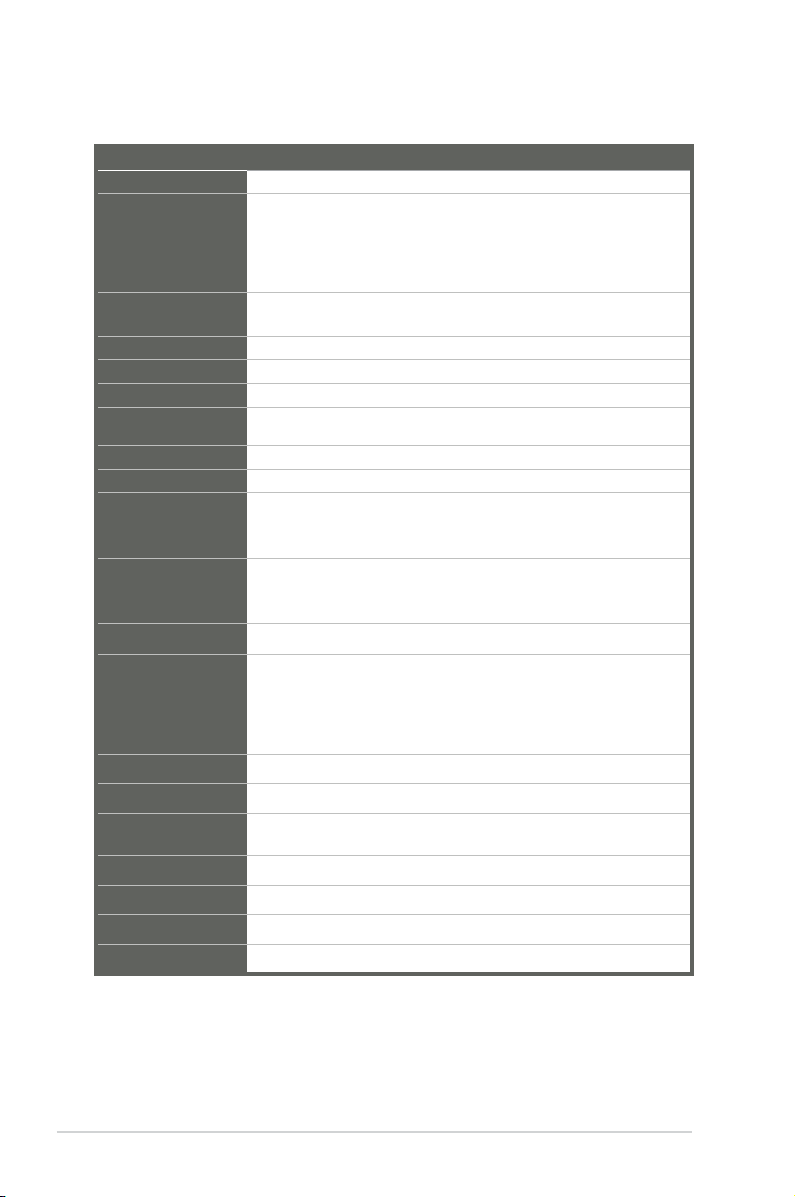
1.3 Specications
SYSTEM
Form factor
Micro ATX
CPU
LGA1155 socket for Intel® 3rd/2nd Generation Core™ i7 / Core™ i5 /
Core™ i3 / Pentium® / Celeron® processors
Supports Intel® 22nm / 32nm CPU
Supports Intel® Turbo Boost Technology 2.0
• The Intel® Turbo Boost Technology 2.0 support depends on the CPU types.
Memory
2 x DIMM (8GB per DIMM), max. 16GB, DDR3 1333 / 1066MHz
Dual-channel memory architecture
Chipset
Intel® H61 Express Chipset
I/O Chipset
Fintech F81866D (5 COM) + 2 x Fintech 81216HD (8 COM)
Ethernet
2 x Realtek® PCIe Gb LAN RTL8111F
BIOS
64Mb Flash ROM, UEFI AMI BIOS, PnP, DMI 2.0, SM BIOS, ACPI
2.0a
Manageability
WOL by PME, PXE
OS
Windows® XP 32-bit, Windows® 7 32/64-bit, Linux Fedora
H/W Status Monitor
Monitors CPU/system temperature
Monitors Vcore, 3.3V/5V/12V voltages
Monitors CPU/chassis fan speed
Expansion slot
1 x PCI Express 2.0 x16 slot
2 x PCI slots
1 x PCI Express Mini Card slot
Battery
Lithium battery
Power requirement
1 x 24-pin ATX connector
1 x 4-pin ATX 12V power connector
1 x CPU fan
2 x Chassis fan
Board size
9.6 in. x 9.6 in. (24.4 cm x 24.4 cm)
Gross weight
1.55 lb (0.7 Kg)
Operating
temperature
32oF~140oF (0oC~60oC)
Storage temperature
-40oF~185oF (-40oC~85oC)
Operating humidity
0%~90% relative humidity, non-condensing
Power compliance
Compliant with Eup/ErP
EMI
CE (include CE-LVD), FCC
(continued on the next page)
Page 7
1-3
Chapter 1: General information
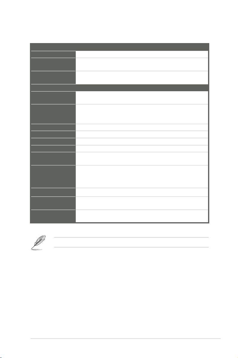
DISPLAY
Chipset
Intel® H61 Express Chipset
Resolution
Up to 1920x1200@75Hz for VGA
Up to 1920x1200@60Hz for LVDS
Output interface
2 x VGA ports
1 x LVDS connector at midboard
I/O
Storage
3 x SATA 3.0Gb/s ports
1 x CFast socket support
Serial port
2 x RS-232/422/485 box header (COM4 support 5V/12V/RI option)
9 x RS-232 box header (COM 3, COM5~8, COM10~13)
2 x COM on rear I/O (support RS-232
)
USB
8 x USB2.0 (4 ports at mid-board, 4 ports at back panel)
DIO
8-bit Digital I/O interface (4-in/4-out)
LPT
1 x LPT connector
RTC
Internal RTC
Keyboard/Mouse
1 x PS/2 Keyboard on rear I/O
1 x PS/2 Mouse on rear I/O
Audio
Realtek® ALC887 7.1-channel high denition audio CODEC
Supports Jack-detection and Anti-pop function
• Use a chassis with HD audio module in the front panel to support a 7.1-channel
audio output.
Ethernet
2 x RJ-45 ports on rear I/O
Display
2 x VGA ports on rear I/O
1 x LVDS connector at midboard
Others
1 x CFast slot
1 x Front panel connector (Pin header)
NOTE: Specications are subject to change without notice.
Page 8

IMBM-H61B
1-4
Page 9
2-1
Chapter 2: Motherboard information
Chapter 2
Motherboard information
2.1 Before you proceed
Take note of the following precautions before you install motherboard components
or change any motherboard settings.
CAUTION!
• Unplug the power cord from the wall socket before touching any
component.
• Before handling components, use a grounded wrist strap or touch a safely
grounded object or a metal object, such as the power supply case, to avoid
damaging them due to static electricity.
• Hold components by the edges to avoid touching the ICs on them.
• Whenever you uninstall any component, place it on a grounded antistatic
pad or in the bag that came with the component.
• Before you install or remove any component, ensure that the ATX power
supply is switched off or the power cord is detached from the power
supply. Failure to do so may cause severe damage to the motherboard,
peripherals, or components.
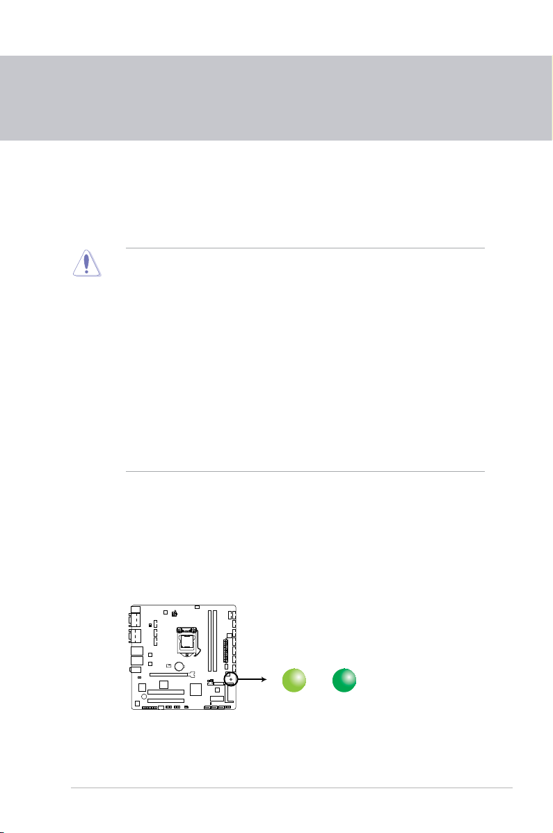
Standby Power LED
The motherboard comes with a standby power LED that lights up to indicate that
the system is ON, in sleep mode, or in soft-off mode. This is a reminder that you
should shut down the system and unplug the power cable before removing or
plugging in any motherboard component. The illustration below shows the location
of the onboard LED.
SB_PWR1
ON
Standby Power
Powered Off
OFF
IMBM-H61B Onboard LED
Page 10
IMBM-H61B
2-2
PCIEX16_1
PCI2
PCI1
DIO
EATXPWR
CPU_FAN1
CHA_FAN1
CHA_FAN2
Lithium Cell
CMOS Power
Super
I/O
BZ1
ALC
887
ASM
1083
EPU
KBMS
SB_PWR1
CLRTC
DRCT1
J2J5J1
J3
LVDSINV
24.4cm(9.6in)
24.4cm(9.6in)
Intel
®
H61
DDR3 DIMM_A1 (64bit, 240-pin module)
DDR3 DIMM_A2 (64bit, 240-pin module)
SATA3G_3 SATA3G_2SATA3G_1
CFAST
Mini_Card
AUDIO
LAN1_USB12
LAN2_USB34
LPT
ATMODE
SPI
VGA1
VGA2
COM1
COM2
LGA1155
F_PANEL
COM6
COM7COM8COM10COM11
COM3COM4COM9
COM12COM13
COM5
RTL
8111F
RTL
8111F
Fintech
81866D-I
CHRONTEL
CH75118
Fintech
81866D-I
EATX12V
USB56 USB78
321 3 34 5 6 4 2
1415
2021
18 17 16
22
19
2
12
13
11
7
8
9
10
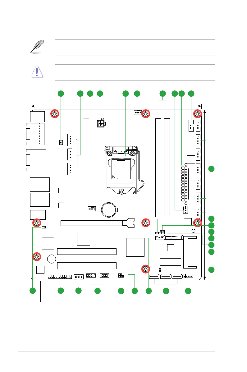
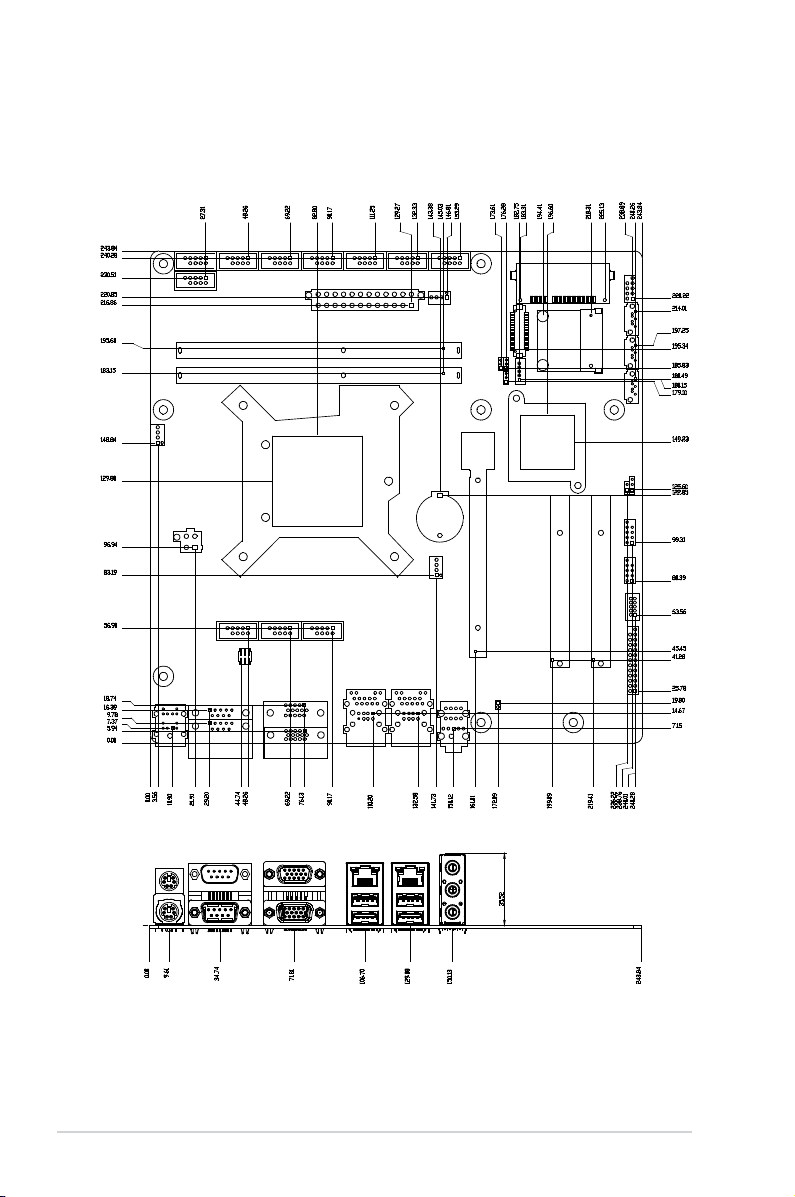
2.2 Motherboard layout
Place this side towards
the rear of the chassis
NOTE: Place eight screws into the holes indicated by circles to secure the
motherboard to the chassis.
CAUTION! Do not overtighten the screws! Doing so can damage the
motherboard.
Page 11

2-3
Chapter 2: Motherboard information
Connectors/Jumpers/Slots
Page
1.
COM4 Ring/+5V/+12V selection (6-pin J5) 2-14
2.
Serial port connectors (10-1 pin COM3/4, COM5~13) 2-21
3.
CPU and chassis fan connectors (4-pin CPU_FAN1, 4-pin CHA_FAN) 2-17
4.
ATX power connectors (24-pin EATXPWR, 4-pin EATX12V) 2-16
5.
Intel® LGA1155 CPU socket 2-6
6.
DDR3 DIMM slots 2-11
7.
Inverter voltage selection (3-pin J2) 2-13
8.
Inverter Back Light Control mode selection (3-pin J3) 2-14
9 Standby Power LED (SB_PWR1) 2-1
10. LVDS panel voltage selection (3-pin J1) 2-13
11. LVDS connector (30-pin LVDS) 2-19
12. CFast slot (CFAST) 2-18
13. SPI programming connector (8-pin SPI) 2-20
14. System panel connector (10-1 pin F_PANEL) 2-18
15. Intel® H61 Serial ATA 3.0Gb/s connectors (7-pin SATA3G_1~3) 2-19
16. Backlight inverter power connector (5-pin INV) 2-22
17. Direct connector (2-pin DRCT1) 2-22
18. Clear RTC RAM (3-pin CLRTC) 2-12
19. USB 2.0 connectors (10-pin USB56, USB78) 2-20
20. Digital I/O connector (10-pin DIO) 2-21
21. LPT connector (26-1 pin LPT) 2-17
22. AT Mode Selection (2-pin ATMODE) 2-14
Page 12
IMBM-H61B
2-4
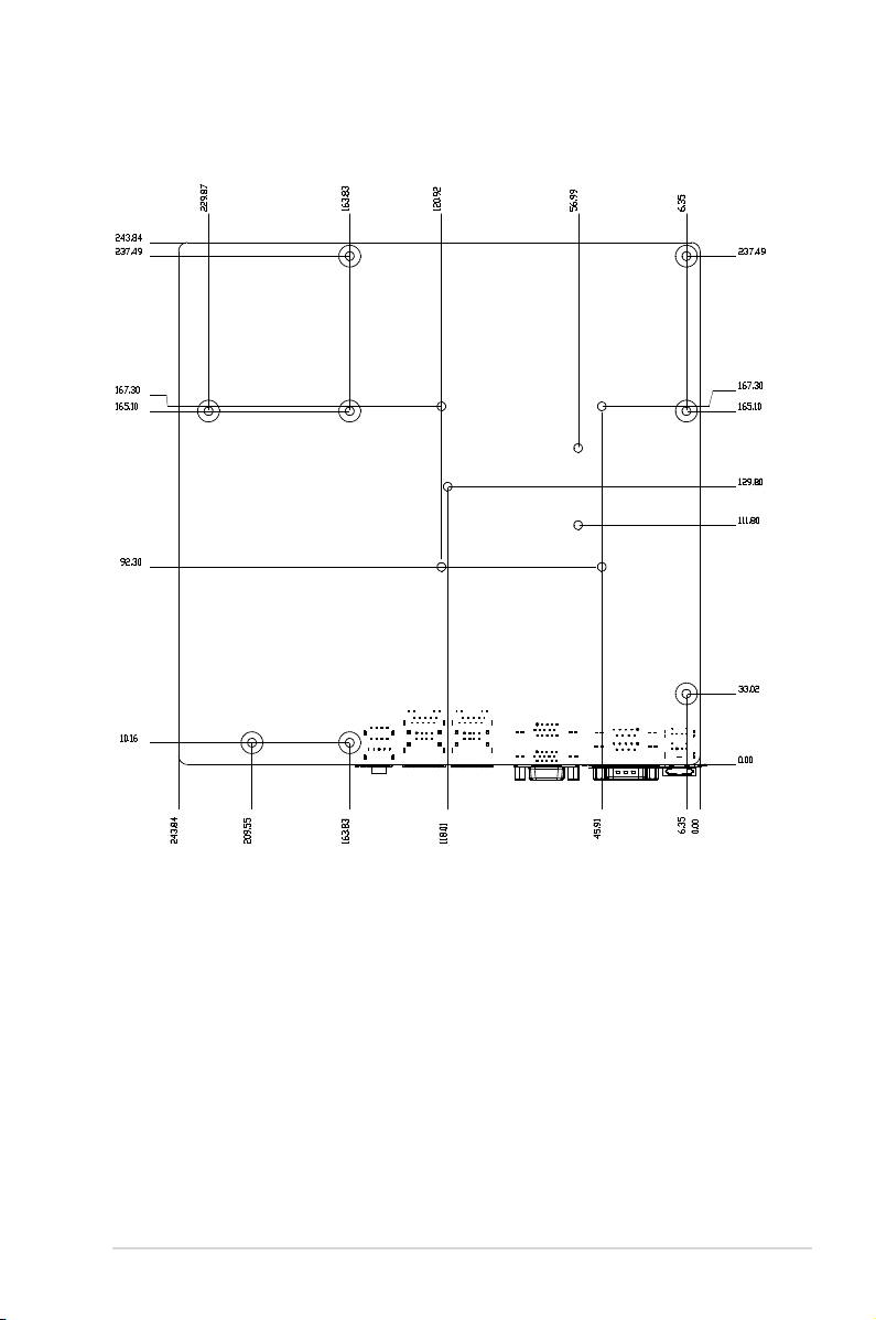
2.3 Screw size
2.3.1 Component side
Page 13
2-5
Chapter 2: Motherboard information
2.3.2 Solder side
Page 14
IMBM-H61B
2-6
IMPORTANT: Unplug all power cables before installing the CPU.
CAUTION!
• Upon purchase of the motherboard, ensure that the PnP cap is on
the socket and the socket contacts are not bent. Contact your retailer
immediately if the PnP cap is missing, or if you see any damage to the
PnP cap/socket contacts/motherboard components. The manufacturer will
shoulder the cost of repair only if the damage is shipment/transit-related.
• Keep the cap after installing the motherboard. The manufacturer will
process Return Merchandise Authorization (RMA) requests only if the
motherboard comes with the cap on the LGA1155 socket.
• The product warranty does not cover damage to the socket contacts
resulting from incorrect CPU installation/removal, or misplacement/loss/
incorrect removal of the PnP cap.
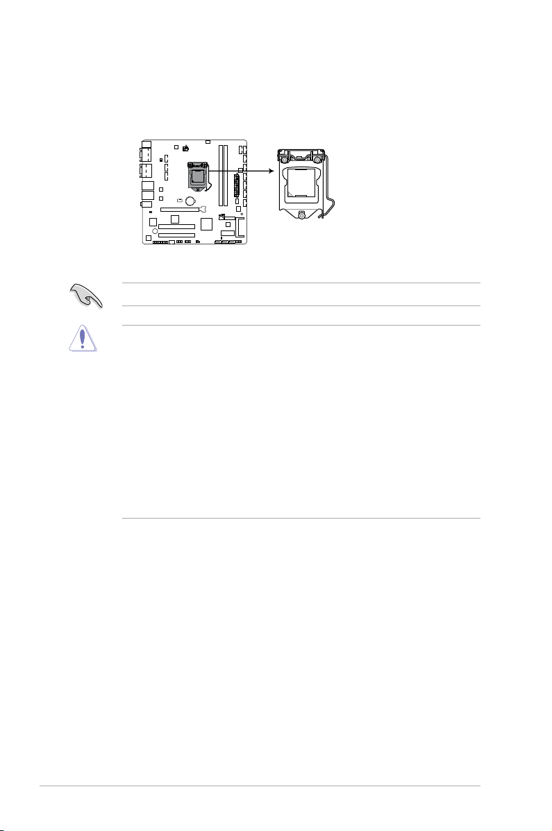
2.4 Central Processing Unit (CPU)
The motherboard comes with a surface mount LGA1155 socket designed for the
Intel® 3rd/2nd Generation Core™ i7 / Core™ i5 / Core™ i3 / Pentium
®
/ Celeron®
processors.
Right
IMBM-H61B CPU socket LGA1155
Page 15
2-7
Chapter 2: Motherboard information
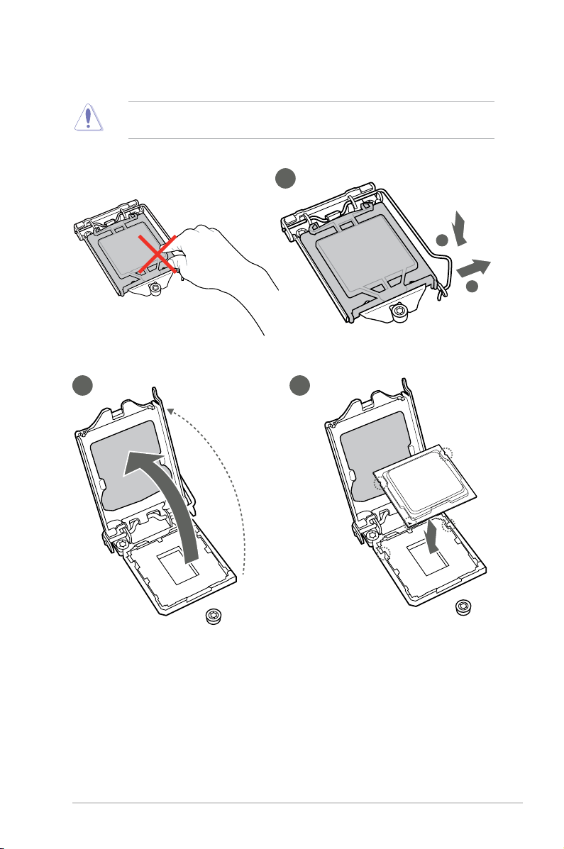
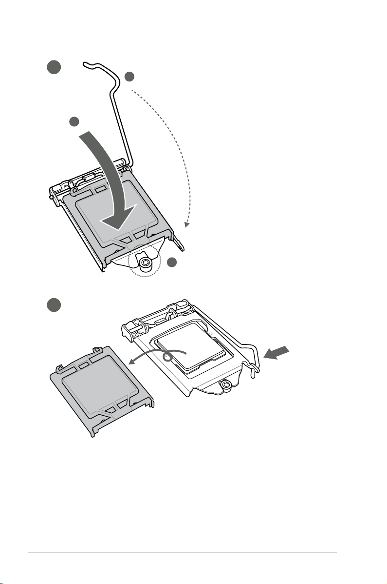
2.4.1 Installing the CPU
1
CAUTION! The LGA1156 CPU is incompatible with the LGA1155 socket. DO
NOT install a LGA1156 CPU on the LGA1155 socket.
A
B
2 3
Page 16
IMBM-H61B
2-8
A
B
C
4
5
Page 17

2-9
Chapter 2: Motherboard information
2.4.2 CPU heatsink and fan assembly installation
CAUTION! Apply the Thermal
Interface Material to the CPU
heatsink and CPU before you
install the heatsink and fan if
necessary.
To install the CPU heatsink and fan assembly
B
A
A
B
1
2
3 4
Page 18

IMBM-H61B
2-10
A
B
B
A
To uninstall the CPU heatsink and fan assembly
2
1
Page 19

2-11
Chapter 2: Motherboard information
2.5 System memory
Installing a DIMM
To remove a DIMM
1
2
3
A
B
Page 20

IMBM-H61B
2-12
2.6 Jumpers
1. Clear RTC RAM (CLRTC)
This jumper allows you to clear the Real Time Clock (RTC) RAM in
CMOS. You can clear the CMOS memory of date, time, and system setup
parameters by erasing the CMOS RTC RAM data. The onboard button
cell battery powers the RAM data in CMOS, which include system setup
information such as system passwords.
To erase the RTC RAM:
1. Turn OFF the computer and unplug the power cord.
2. Move the jumper cap from pins 1-2 (default) to pins 2-3. Keep the cap on
pins 2-3 for about 5~10 seconds, then move the cap back to pins 1-2.
3. Plug the power cord and turn ON the computer.
4. Hold down the
<Del> key during the boot process and enter BIOS setup
to reenter data.
CAUTION! Except when clearing the RTC RAM, never remove the cap on
CLRTC jumper default position. Removing the cap will cause system boot
failure!
NOTES:
• If the steps above do not help, remove the onboard battery and move the
jumper again to clear the CMOS RTC RAM data. After clearing the CMOS,
reinstall the battery.
• You do not need to clear the RTC when the system hangs due to
overclocking. For system failure due to overclocking, use the CPU
Parameter Recall (C.P.R) feature. Shut down and reboot the system so the
BIOS can automatically reset parameter settings to default values.
IMBM-H61B
IMBM-H61B Clear RTC RAM
1 2 2 3
Protected
(Default)
Clear
CLRTC
Page 21

2-13
Chapter 2: Motherboard information
2. LVDS panel voltage selection (3-pin J1)
Pins
+5V 1-2
+3.3V (Default) 2-3
IMBM-H61B
IMBM-H61B LVDS Panel Voltage Selection
1 2 2 3
+3.3V
(Default)
+5V
J1
3. Inverter voltage selection (3-pin J2)
Pins
+12V 1-2
+5V (Default) 2-3
IMBM-H61B
IMBM-H61B Inverter Voltage Selection
1 2 2 3
+5V
(Default)
+12V
J2
4. Inverter Backlight Control mode selection (3-pin J3)
IMBM-H61B
IMBM-H61B Mode Selection for Back Light Control of Inverter
1 2 2 3
DC Voltage Control
(Default)
PWM Control
J3
Page 22

IMBM-H61B
2-14
5. COM4 Ring/+5V/+12V selection (6-pin J5)
Pins
+12V 1-2
+5V 3-4
Ring (Default) 5-6
IMBM-H61B
IMBM-H61B COM2 Ring/+5V/+12V Selection
5 6 3 4 1 2
Ring
(Default)
+5V +12V
J5
Pins
DC Voltage Control (Default) 1-2
PWM Control 2-3
6. AT Mode selection (2-pin ATMODE)
Pins
1 (Default) ATX
1-2 AT Mode
IMBM-H61B
ATX
AT MODE
ATMODE
IMBM-H61B ATMODE setting
PIN 1
NOTE: Jumper setting of ATMode should be consistent with the setting of
AT/ATX Power Type in BIOS. Refer to section 3.4.9 APM in Chapter 3.
Page 23

2-15
Chapter 2: Motherboard information
5. Line In port (light blue). This port connects to the tape, CD, DVD player, or
other audio sources.
6. Line Out port (lime).
This port connects to a headphone or a speaker. In the
4, 6, and 8-channel congurations, the function of this port becomes Front
Speaker Out.
7. Microphone port (pink).
This port connects to a microphone.
2.7 Connectors
2.7.1 Rear panel connectors
LAN port
Speed
LED
Activity
Link LED
ACT/LINK LED SPEED LED
Status Description Status Description
OFF No link OFF 10 Mbps connection
ORANGE Linked ORANGE 100 Mbps connection
BLINKING Data activity GREEN 1 Gbps connection
1. PS/2 Mouse port (green). This port is for a PS/2 mouse.
2. Serial ports.
These ports connect a modem, or other devices that conform
with serial specication.
3. Video Graphics Adapter (VGA) port.
This 15-pin port is for a VGA monitor
or other VGA-compatible devices.
4. LAN (RJ-45) ports.
These ports allow Gigabit connection to a Local Area
Network (LAN) through a network hub. Refer to the table below for the LAN
port LED indications.
LAN port LED indications
3
8
4
3
5 6
7
1
9
2
2
NOTE: Tocongurean8-channelaudiooutput:
Use a chassis with HD audio module in the front panel to support an 8-
channel audio output.
Page 24

IMBM-H61B
2-16
Audio 2, 4, 6, 8-channel conguration
Port 2-channel 4-channel 6-channel 8-channel
Light Blue (Rear
panel)
Line In Rear Speaker Out Rear Speaker Out Rear Speaker Out
Lime (Rear panel) Line Out Front Speaker Out Front Speaker Out Front Speaker Out
Pink (Rear panel) Mic In Mic In Bass/Center Bass/Center
Lime (Front panel) - - - Side Speaker Out
8. USB 2.0 ports. These two 4-pin Universal Serial Bus (USB) ports are
available for connecting USB 2.0/1.1 devices.
9. PS/2 Keyboard port (purple).
This port is for a PS/2 keyboard.
2.7.2 Internal connectors
IMPORTANT:
• For a fully congured system, we recommend that you use a power supply
unit (PSU) that complies with ATX 12 V Specication 2.0 (or later version)
and provides a minimum power of 350 W.
• DO NOT forget to connect the 4-pin ATX +12V power plug. Otherwise, the
system will not boot up.
• We recommend that you use a PSU with higher power output when
conguring a system with more power-consuming devices. The system
may become unstable or may not boot up if the power is inadequate.
1. ATX power connectors (24-pin EATXPWR, 4-pin EATX12V)
These connectors are for ATX power supply plugs. The power supply plugs
are designed to t these connectors in only one orientation. Find the proper
orientation and push down rmly until the connectors completely t.
IMBM-H61B ATX power connectors
EATXPWR
PIN 1
PIN 1
GND
+5 Volts
+5 Volts
+5 Volts
-5 Volts
GND
GND
GND
PSON#
GND
-12 Volts
+3 Volts
+3 Volts
+12 Volts
+12 Volts
+5V Standby
Power OK
GND
+5 Volts
GND
+5 Volts
GND
+3 Volts
+3 Volts
EATX12V
+12V DC
+12V DC
GND
GND
NOTE: Refer to the audio conguration table below for the function of the
audio ports in the 2, 4, 6, or 8-channel conguration.
Page 25

2-17
Chapter 2: Motherboard information
CAUTION: Do not forget to connect the fan cables to the fan connectors.
Insufcient air ow inside the system may damage the motherboard
components. These are not jumpers! Do not place jumper caps on the fan
connectors!
NOTES:
• The CPU_FAN connector supports a CPU fan of maximum 2A (24 W) fan
power.
• Only the 4-pin CPU fan and 4-pin chassis fan support the Q-Fan feature.
2. CPU and chassis fan connectors (4-pin CPU_FAN, 4-pin CHA_FAN)
Connect the fan cables to the fan connectors on the motherboard, ensuring
that the black wire of each cable matches the ground pin of the connector.
IMBM-H61B Fan connectors
CHA_FAN1
CHA FAN PWM
CHA FAN SENSE
CHA FAN VCC
GND
CHA_FAN2
GND
CHA FAN VCC
CHA FAN SENSE
CHA FAN PWM
CPU_FAN1
CPU FAN PWM
CPU FAN SENSE
CPU FAN VCC
GND
3. LPT connector (26-1 pin LPT)
The LPT (Line Printing Terminal) connector supports devices such as a printer. LPT is
standardized as IEEE 1284, which is the parallel port interface on IBM PC-compatible
computers.
IMBM-H61B Parallel Port Connector
PIN 1
LPT
STB#
PD0
PD1
PD2
PD3
PD4
PD5
PD6
PD7
ACK#
BUSY
PE
SLCT
AFD
ERR#
INIT#
SLIN#
GND
GND
GND
GND
GND
GND
GND
GND
Page 26

IMBM-H61B
2-18
4. System panel connector (10-1 pin F_PANEL)
This connector supports several chassis-mounted functions.
• System power LED (2-pin PLED)
This 2-pin connector is for the system power LED. Connect the chassis
power LED cable to this connector. The system power LED lights up when
you turn on the system power, and blinks when the system is in sleep mode.
•
Hard disk drive activity LED (2-pin +HDLED)
This 2-pin connector is for the HDD Activity LED. Connect the HDD Activity
LED cable to this connector. The IDE LED lights up or ashes when data is
read from or written to the HDD.
•
ATX power button/soft-off button (2-pin PWRBTN)
This 2-pin connector is for the system power button.
•
Reset button (2-pin RESET)
This 2-pin connector is for the chassis-mounted reset button for system
reboot without turning off the system power.
IMBM-H61B System panel connector
PIN 1
PWR BTN
PLED+
PLED-
PWR
GND
HD_LED+
HD_LED-
Ground
HWRST#
(NC)
F_PANEL
PWR LED
+HD_LED RESET
5. CFast slot (CFAST)
The CFast slot is for CFast ash memory cards.
IMBM-H61B CF Connector
NOTE: The CFast ash memory card is purchased separately.
Page 27

2-19
Chapter 2: Motherboard information
6. Intel® H61 Serial ATA 3.0Gb/s connectors (7-pin SATA3G_1~3)
These connectors connect to Serial ATA 3.0 Gb/s hard disk drives and optical
drives via Serial ATA 3.0 Gb/s signal cables.
NOTES:
• You must install Windows
®
XP Service Pack 3 or later version before using
Serial ATA hard disk drives.
• Due to H61 Chipset limitation, AHCI Mode only works on Windows
®
Vista/
Windows® 7. Please use IDE Mode on Windows® XP.
• To congure the SATA type in BIOS, click
Advanced tab > SATA
Conguration> SATA Mode Selection. See section 3.4.3 SATA
Conguration for details.
• When using hot-plug and NCQ, set the
SATA Mode Selection item in the
BIOS to [AHCI]. See section 3.4.3SATAConguration for details.
SATA3G_3
GND
RSATA_RXP3
RSATA_RXN3
GND
RSATA_TXN3
RSATA_TXP3
GND
SATA3G_1
GND
RSATA_RXP1
RSATA_RXN1
GND
RSATA_TXN1
RSATA_TXP1
GND
SATA3G_2
GND
RSATA_RXP2
RSATA_RXN2
GND
RSATA_TXN2
RSATA_TXP2
GND
IMBM-H61B Intel® SATA 3.0Gb/s connectors
7. LVDS connector (30-pin LVDS)
This connector is for a LCD monitor that supports Low-voltage differential
signaling (LVDS) interface.
IMBM-H61B LVDS connector
LVDS
PIN 1
Back Light Control for DC mode
GND
LVDS0_CLK+
GND
LVDS0_D0+
LVDS0_D1+
LVDS0_D2+
LVDS0_D3+
EDID_Clk
LVDS1_D0+
LVDS1_D1+
LVDS1_D2+
LVDS1_D3+
GND
LVDS1_CLK+
LVDS Panel Enable
LVDS VCC
LVDS0_CLK-
LVDS VCC
LVDS0_D0-
LVDS0_D1-
LVDS0_D2-
LVDS0_D3-
EDID_Data
LVDS1_D0-
LVDS1_D1-
LVDS1_D2-
LVDS1_D3-
LVDS VCC
LVDS1_CLK-
Page 28

IMBM-H61B
2-20
8. USB 2.0 connectors (10-1 pin USB56, USB78)
These connectors are for USB 2.0 ports. Connect the USB module cable
to any of these connectors, then install the module to a slot opening at the
back of the system chassis. These USB connectors comply with USB 2.0
specication that supports up to 480 Mbps connection speed.
CAUTION! Never connect a 1394 cable to the USB connectors. Doing so will
damage the motherboard!
NOTE: The USB module cable is purchased separately.
IMBM-H61B Front USB 2.0 Header connectors
+5V_USB_P78
S_USB_PN7
S_USB_PP7
GND
NC
+5V_USB_P78
S_USB_PN6
S_USB_PP6
GND
USB56
+5V_USB_P910
S_USB_PN9
S_USB_PP9
GND
NC
+5V_USB_P910
S_USB_PN8
S_USB_PP8
GND
USB78
PIN 1 PIN 1
9. SPI programming connector (8-pin SPI)
Use this connector to ash BIOS SPI ROM.
IMBM-H61A
IMBM-H61A SPI programming connector
PIN 1
SPI
(NC)
SPI_MOSI
SPI_CLK
GND
(NC)
SPI_MISO
SPI_CS#
+V3.3SPI
Page 29

2-21
Chapter 2: Motherboard information
10. Serial port connectors (10-1 pin COM1/2, COM5~13)
These connectors are for serial (COM) ports. Connect the serial port module
cable to this connector, then install the module to a slot opening at the back
of the system chassis.
NOTE: The COM module is purchased separately.
IMBM-H61B Serial port connectors
PIN 1
COM3
RI
RTS
GND
TXD
DCD
CTS
DSR
DTR
RXD
PIN 1
COM4
RI
RTS
GND
TXD
DCD
CTS
DSR
DTR
RXD
PIN 1
COM9
RI
RTS
GND
TXD
DCD
CTS
DSR
DTR
RXD
PIN 1
COM11
RI
RTS
GND
TXD
DCD
CTS
DSR
DTR
RXD
PIN 1
COM12
RI
RTS
GND
TXD
DCD
CTS
DSR
DTR
RXD
PIN 1
COM13
RI
RTS
GND
TXD
DCD
CTS
DSR
DTR
RXD
PIN 1
COM7
RI
RTS
GND
TXD
DCD
CTS
DSR
DTR
RXD
PIN 1
COM8
RI
RTS
GND
TXD
DCD
CTS
DSR
DTR
RXD
PIN 1
COM10
RI
RTS
GND
TXD
DCD
CTS
DSR
DTR
RXD
PIN 1PIN 1
COM6
RI
RTS
GND
TXD
DCD
CTS
DSR
DTR
RXD
COM5
RI
RTS
GND
TXD
DCD
CTS
DSR
DTR
RXD
IMBM-H61B DIO connector
PIN 1
DIO1
GPIO50(DIO_P#1)
GPIO53 (DIO_P#3)
GPIO55 (DIO_P#5)
GPIO57(DIO_P#7)
+5V
GPIO51 (DIO_P#2)
GPIO54(DIO_P#4)
GPIO56(DIO_P#6)
GPIO58 (DIO_P#8)
GND
11. Digital I/O connector (10-pin DIO)
This connector includes 8 I/O lines. All of the Digital I/O lines are
programmable and each I/O pin can be individually programmed to support
various devices.
NOTE: To congure the I/O pins in BIOS, click Advanced tab > SIO GPIO >
GPIO 50~57. See section 3.4.6 SIO GPIO for details.
Page 30

IMBM-H61B
2-22
12. Backlight inverter power connector (5-pin INV)
Connect the backlight inverter power cable to this connector.
Inverter VCC
Back Light Control
GND
GND
Back Light Enable
IMBM-H61B Inverter Connector
INV
NOTE: The backlight inverter power cable is purchased separately.
13. Direct connector (2-pin DRCT)
This connector is for the chassis-mounted button that supports the
DirectBIOS function. Connect the button cable that supports DirectBIOS,
from the chassis to this connector on the motherboard.
IMBM-H61B DRCT connector
PIN 1
DRCT
WIN8_RE_BUTTON#
GND
NOTE: Ensure that your chassis comes with the button cable that supports
the DirectBIOS feature. Refer to the technical documentation that came with the
chassis for details.
Page 31

Chapter 3: BIOS setup
3-1
3.1 BIOS setup program
Use the BIOS Setup program to update the BIOS or congure its parameters. The
BIOS screens include navigation keys and brief online help to guide you in using
the BIOS Setup program.
Entering BIOS Setup at startup
To enter BIOS Setup at startup:
Press <Delete> during the Power-On Self Test (POST). If you do not press
<Delete>, POST continues with its routines.
Entering BIOS Setup after POST
To enter BIOS Setup after POST:
Press <Ctrl>+<Alt>+<Del> simultaneously.
Press the reset button on the system chassis.
Press the power button to turn the system off then back on. Do this option only
if you failed to enter BIOS Setup using the rst two options.
NOTE: Using the power button, reset button, or the <Ctrl>+<Alt>+<Del> keys
to force reset from a running operating system can cause damage to your data
or system. We recommend to always shut down the system properly from the
operating system.
IMPORTANT:
• The default BIOS settings for this motherboard apply for most conditions
to ensure optimum performance. If the system becomes unstable after
changing any BIOS settings, load the default settings to ensure system
compatibility and stability. Select any of the load default settings under the
Save & Exit Menu. See section 3.8 Save & Exit Menu.
• Ensure that a USB mouse is connected to your motherboard if you want to
use the mouse to control the BIOS setup program.
• The BIOS setup screens shown in this section are for reference purposes
only, and may not exactly match what you see on your screen.
•
•
•
•
Chapter 3
BIOS setup
Page 32

3-2
IMBM-H61B
Menu bar
The menu bar on top of the screen has the following main items:
Main For changing the basic system conguration.
Advanced For changing the advanced system settings.
Boot For changing the system boot conguration.
Tool For conguring options for special functions.
Exit For selecting the exit options and loading default settings.
3.2 BIOS menu screen
Navigation keys
General help
Menu bar
Submenu items
Congurationelds
Menu items
Pop-up window
Back button
Page 33

Chapter 3: BIOS setup
3-3
Menu items
The highlighted item on the menu bar displays the specic items for that menu. For
example, selecting Main shows the Main menu items.
The other items (Advanced, Monitor, Boot, Tool, and Exit) on the menu bar have
their respective menu items.
Back button
This button appears when entering a submenu. Press <Esc> or use the USB
mouse to click this button to return to the previous menu screen.
Submenu items
A greater than sign (>) before each item on any menu screen means that the item
has a submenu. To display the submenu, select the item and press <Enter>.
Pop-up window
Select a menu item and press <Enter> to display a pop-up window with the
conguration options for that item.
Navigation keys
At the bottom right corner of the menu screen are the navigation keys for the BIOS
setup program. Use the navigation keys to select items in the menu and change
the settings.
General help
At the top right corner of the menu screen is a brief description of the selected
item.
Congurationelds
These elds show the values for the menu items. If an item is user-congurable,
you can change the value of the eld opposite the item. You cannot select an item
that is not user-congurable.
A congurable eld is highlighted when selected. To change the value of a eld,
select it and press <Enter> to display a list of options.
Page 34

3-4
IMBM-H61B
3.3 Main menu
The Main menu screen appears when you enter the Advanced Mode of the BIOS
Setup program. The Main menu provides you an overview of the basic system
information, and allows you to set the system date, time, language, and security
settings.
3.3.1 System Language [English]
Allows you to choose the BIOS language version from the options. Conguration
options: [English]
3.3.2 System Date [Day xx/xx/xxxx]
Allows you to set the system date.
3.3.3 System Time [xx:xx:xx]
Allows you to set the system time.
3.3.4 Security
The Security menu items allow you to change the system security settings.
NOTES:
• If you have forgotten your BIOS password, erase the CMOS Real Time
Clock (RTC) RAM to clear the BIOS password. See section 2.6 Jumpers
for information on how to erase the RTC RAM.
• The
Administrator or User Password items on top of the screen show
the default Not Installed. After you set a password, these items show
Installed.
Page 35

Chapter 3: BIOS setup
3-5
Administrator Password
If you have set an administrator password, we recommend that you enter the
administrator password for accessing the system. Otherwise, you might be able to
see or change only selected elds in the BIOS setup program.
To set an administrator password:
1. Select the
Administrator Password item and press <Enter>.
2. From the
Create New Password box, key in a password, then press
<Enter>.
3. Conrm the password when prompted.
To change an administrator password:
1. Select the
Administrator Password item and press <Enter>.
2. From the
Enter Current Password box, key in the current password, then
press <Enter>.
3. From the
Create New Password box, key in a new password, then press
<Enter>.
4. Conrm the password when prompted.
To clear the administrator password, follow the same steps as in changing an
administrator password, but press <Enter> when prompted to create/conrm the
password. After you clear the password, the Administrator Password item on top
of the screen shows Not Installed.
User Password
If you have set a user password, you must enter the user password for accessing
the system. The User Password item on top of the screen shows the default Not
Installed. After you set a password, this item shows Installed.
To set a user password:
1. Select the
User Password item and press <Enter>.
2. From the
Create New Password box, key in a password, then press
<Enter>.
3. Conrm the password when prompted.
To change a user password:
1. Select the
User Password item and press <Enter>.
2. From the
Enter Current Password box, key in the current password, then
press <Enter>.
3. From the
Create New Password box, key in a new password, then press
<Enter>.
4. Conrm the password when prompted.
Page 36

3-6
IMBM-H61B
CAUTION: Be cautious when changing the settings of the Advanced menu
items. Incorrect eld values can cause the system to malfunction.
3.4 Advanced menu
The Advanced menu items allow you to change the settings for the CPU and other
system devices.
To clear the user password, follow the same steps as in changing a user password,
but press <Enter> when prompted to create/conrm the password. After you clear
the password, the User Password item on top of the screen shows Not Installed.
Page 37

Chapter 3: BIOS setup
3-7
Intel Adaptive Thermal Monitor [Enabled]
[Enabled] Enables the overheated CPU to throttle its clock speed to cool
down.
[Disabled] Disables the CPU thermal monitor function.
Active Processor Cores [All]
Allows you to choose the number of CPU cores to activate in each processor
package. Conguration options: [All] [1] [2] [3]
Limit CPUID Maximum [Disabled]
[Enabled] Allows legacy operating systems to boot even without support for
CPUs with extended CPUID functions.
[Disabled] Disables this function.
Execute Disable Bit [Enabled]
[Enabled] Enables the No-Execution Page Protection Technology.
[Disabled] Forces the XD feature ag to always return to zero (0).
Intel Virtualization Technology [Disabled]
[Enabled] Allows a hardware platform to run multiple operating systems
separately and simultaneously, enabling one system to virtually
function as several systems.
[Disabled] Disables this function.
Hardware Prefetcher [Enabled]
[Disabled] Disables this function.
[Enabled] Allows you to turn on /off the Mid Level Cache (L2) streamer
prefetcher.
Adjacent Cache Line Prefetch [Enabled]
[Disabled] Disables this function.
[Enabled] Allows a hardware platform to perform adjacent cache line
prefetching.
3.4.1 CPUConguration
The items in this menu show the CPU-related information that the BIOS
automatically detects.
IMPORTANT: The items shown in submenu may be different due to the CPU
you installed.
Page 38

3-8
IMBM-H61B
3.4.2 PCHConguration
High Precision Timer [Enabled]
Allows you to enable or disable the High Precision Event Timer.
Conguration options: [Enabled] [Disabled]
Intel(R) Rapid Start Technology
Intel(R) Rapid Start Technology [Disabled]
Allows you to enable or disable the Intel® Rapid Start Technology. Conguration
options: [Enabled] [Disabled]
NOTE: The following three items appear only when you set the Intel(R) Rapid
Start Technology to [Enabled].
Entry on S3 RTC Wake [Enabled]
Allows you to enable or disable the iFFS invocation upon S3 RTC wake. Conguration
options: [Enabled] [Disabled]
Entry After [Immediately]
This item appears only when you set the Entry on S3 RTC Wake to [Enabled] and
allows you to set the RTC wake timer at S3 entry. Conguration options: [Immediately]
[1 minute] [2 minutes] [5 minutes] [10 minutes] [15 minutes] [30 minutes] [1 hour] [2
hours]
Active Page Threshold Support [Enabled]
Allows you to enable or disable the Active Page Threshold Support. Conguration
options: [Enabled] [Disabled]
Active Memory Threshold [x]
This item appears only when you set the Active Page Threshold Support to
[Enabled] and allows you to set the Active Memory Threshold. When the partition size
is larger than the Active Page Threshold size, the system will try to support the Intel(R)
Rapid Start Technology. When the item is set to zero, the system automatically checks
whether the partition size is enough at S3 entry. Key in the desired value using the
numeric keypad.
Intel(R) Smart Connect Technology
ISCTConguration[Disabled]
Allows you to enable or disable the ISCT conguration. Conguration options:
[Enabled] [Disabled]
Page 39

Chapter 3: BIOS setup
3-9
3.4.3 SATAConguration
While entering Setup, the BIOS automatically detects the presence of SATA devices.
The SATA Port items show Not Present if no SATA device is installed to the
corresponding SATA port.
SATA Mode Selection [IDE]
Allows you to set the SATA conguration.
[Disabled] Disables the SATA controller.
[IDE] Set to [IDE] when you want to use the Serial ATA hard disk drives as
Parallel ATA physical storage devices.
[AHCI] Set to [AHCI] when you want the SATA hard disk drives to use the AHCI
(Advanced Host Controller Interface). The AHCI allows the onboard
storage driver to enable advanced Serial ATA features that increases
storage performance on random workloads by allowing the drive to
internally optimize the order of commands.
S.M.A.R.T. Status Check [Enabled]
S.M.A.R.T. (Self-Monitoring, Analysis and Reporting Technology) is a monitor system.
When read/write of your hard disk errors occur, this feature allows the hard disk to report
warning messages during the POST. This item appears only when you set the previous
item to [IDE] or [AHCI]. Conguration options: [Enabled] [Disabled]
Hot Plug [Disabled]
This item only appears when you set the SATA Mode Selection item to [AHCI] and
allows you to enable or disable the hot-plug support for each SATA port. Conguration
options: [Enabled] [Disabled]
3.4.4 SystemAgentConguration
Memory Remap Feature [Enabled]
Enables or disables the memory remap feature. Conguration options: [Enabled]
[Disabled]
GraphicsConguration
Primary Display [Auto]
Allows you to decide which graphics controller to use as the primary boot device.
Conguration options: [Auto] [iGPU] [PCIE] [PCI]
iGPU Memory [Auto]
Allows you to select the system memory size allocated to DVMT 5.0 used by iGPU.
Conguration options: [Auto] [32M] [64M] [96M] [128M] ~ [448M] [480M] [512M] [1024M]
Render Standby [Enabled]
Allows you to enable Intel Graphics Render Standby support to reduce the power
Page 40

3-10
IMBM-H61B
consumption for iGPU while the system is idle. Conguration options: [Disabled]
[Enabled]
iGPU Multi-Monitor [Disabled]
Allows you to enable or disable iGPU Multi-Monitor support for add-on graphics
devices. The iGPU shared memory size will be xed at 64MB. Conguration options:
[Disabled] [Enabled]
3.4.5 USBConguration
The items in this menu allow you to change the USB-related features.
NOTE: The USB Devices item shows the auto-detected values. If no USB
device is detected, the item shows None.
Legacy USB Support [Enabled]
[Enabled] Enables the support for USB devices on legacy operating systems
(OS).
[Disabled] The USB devices can be used only for the BIOS setup program.
[Auto] Allows the system to detect the presence of USB devices at
startup. If detected, the USB controller legacy mode is enabled. If
no USB device is detected, the legacy USB support is disabled.
EHCI Hand-off [Disabled]
[Enabled] Enables the support for operating systems without an EHCI
hand-off feature.
[Disabled] Disables the function.
3.4.6 SIO GPIO
GPIO 50~57 [Input]
Allows you to congure the digital signal of the GPIO (General Purpose Input/
Output) pins 50~57. Conguration options: [Input] [Output High] [Output Low]
3.4.7 CH7511B Panel Controller
CH7511B Panel Type [1024x768 18Bit LVDS]
Allows you to congure CH7511B panel used by Internal Graphics Device.
Conguration options: [1366x768 18Bit LVDS] [1024x768 18Bit LVDS] [1024x768
24Bit LVDS] [1280x1024 48Bit LVDS] [1600x1200 48Bit LVDS] [1280x768 18Bit
LVDS] [1280x768 24Bit LVDS] [1366x768 24Bit LVDS] [1444x900 48Bit LVDS]
[1920x1080 48Bit LVDS] [1280x1024 18Bit LVDS] [1280x1024 24Bit LVDS]
Page 41

Chapter 3: BIOS setup
3-11
Primary IGFX Boot Display [Auto]
Select the integrated display device which is activated during POST. Your selection
does not take effect if you have installed an external graphics device. Secondary
boot display selection will appear based on your selection. VGA modes can be
supported only on the primary display. Conguration options: [Auto] [CRT] [DVI]
[LVDS]
CH7511B Backlight Control Mode [DC Mode]
Allows you to select CH7511B Backlight Control mode. Conguration options: [DC
Mode] [PWM Mode]
Backlight Brightness Setting [75]
Allows you to set the backlight brightness. Select a larger number for a brighter
backlight. Conguration options: [0] [25] [50] [75] [100]
3.4.8 OnboardDevicesConguration
HD Audio Controller [Enabled]
[Enabled] Enables the High Denition Audio Controller.
[Disabled] Disables the controller.
Realtek LAN1 Controller [Enabled]
[Enabled] Enables the Realtek LAN controller 1.
[Disabled] Disables the controller.
Realtek LAN1 PXE OPROM [Disabled]
This item appears only when you set the Realtek LAN1 Controller item to
[Enabled] and allows you to enable or disable the PXE OptionRom of the Realtek
LAN controller 1. Conguration options: [Enabled] [Disabled]
Realtek LAN2 Controller [Enabled]
[Enabled] Enables the Realtek LAN controller 2.
[Disabled] Disables the controller.
Realtek LAN2 PXE OPROM [Disabled]
This item appears only when you set the Realtek LAN2 Controller item to
[Enabled] and allows you to enable or disable the PXE OptionRom of the Realtek
LAN controller 2. Conguration options: [Enabled] [Disabled]
Serial Port 1-9 [Enabled]
Allows you to enable or disable serial ports (COM) 1-9. Conguration options:
[Enabled] [Disabled]
RS Mode [RS232]
Allows you to congure the serial communications standard of serial port (COM) 4.
Conguration options: [RS232] [RS422] [RS485]
Page 42

3-12
IMBM-H61B
RS Mode [RS232]
Allows you to congure the serial communications standard of serial port (COM) 9.
Conguration options: [RS232] [RS422] [RS485]
Serial Port 10~13 [Enabled]
Allows you to enable or disable serial ports (COM) 10~13. Conguration options:
[Enabled] [Disabled]
Parallel Port [Enabled]
Allows you to enable or disable the parallel port (LPT). Conguration options:
[Enabled] [Disabled]
Change Settings [Auto]
Allows you to select the Parallel Port base address. Conguration options:
[Auto] [IO=378h; IRQ=5] [IO=378h; IRQ=5,6,7,9,10,11,12] [IO=3BCh;
IRQ=5,6,7,9,10,11,12]
Device Mode [STD Printer Mode]
Allows you to set the Printer port mode. Conguration options: [STD Printer Mode]
[SPP Mode] [EPP-1.9 and SPP Mode] [EPP-1.7 and SPP Mode]
3.4.9 APM
ErP Ready [Enabled]
This item allows user to switch off some power at S5 to get the system ready for
ErP requirement. When set to Enabled, all other PME options will be switched off.
Conguration options: [Disabled] [Enabled]
AT/ATX Power Type [ATX Mode]
Allows you to set the AT/ATX power type. Conguration options: [ATX Mode] [AT
Mode]
Restore AC Power Loss [Power Off]
[Power On] The system goes into on state after an AC power loss.
[Power Off] The system goes into off state after an AC power loss.
[Last State] The system goes into either off or on state, whatever the system
state was before the AC power loss.
Power On By PCI [Disabled]
[Disabled] Disables the PCI devices to generate a wake event.
[Enabled] Enables the PCI devices to generate a wake event.
Power On By PCIE [Disabled]
[Disabled] Disables the PCIE devices to generate a wake event.
[Enabled] Enables the PCIE devices to generate a wake event.
Page 43

Chapter 3: BIOS setup
3-13
Power On By Ring [Disabled]
[Disabled] Disables Ring to generate a wake event.
[Enabled] Enables Ring to generate a wake event.
Power On By RTC [Disabled]
[Disabled] Disables RTC to generate a wake event.
[Enabled] When set to [Enabled], the items RTC Alarm Date (Days) and
Hour/Minute/Second will become user-congurable with set
values.
RTC Alarm Date (Days)
This item appears only when you set the previous item to [Enabled] and allows you
to select RTC alarm time (days). When you set the time to zero, the RTC alarms
everyday. Use <+> and <-> keys to adjust the time.
- Hour / - Mimute / - Second
Allows you to set the RTC alarm time. Use <+> and <-> keys to adjust the time.
3.4.10 Network Stack
Network Stack [Disabled]
This item allows user to disable or enable the UEFI network stack. Conguration
options: [Disabled] [Enabled]
Ipv4 PXE Support [Enabled]
This item appears only when you set the Network Stack item to [Enabled]. When
this item is disabled, the IPV4 PXE boot option will not be created. Conguration
options: [Disabled] [Enabled]
Ipv6 PXE Support [Enabled]
This item appears only when you set the Network Stack item to [Enabled]. When
this item is disabled, the IPV6 PXE boot option will not be created. Conguration
options: [Disabled] [Enabled]
Page 44

3-14
IMBM-H61B
3.5 Monitor menu
The Monitor menu displays the system temperature/power status, and allows you
to change the fan settings.
3.5.1 CPU Temperature / MB Temperature [xxxºC/xxxºF]
The onboard hardware monitor automatically detects and displays the CPU
and motherboard temperatures. Select Ignore if you do not wish to display the
detected temperatures.
3.5.2 CPU / Chassis Fan Speed [xxxx RPM] or [Ignore] /
[N/A]
The onboard hardware monitor automatically detects and displays the CPU and
chassis fan speeds in rotations per minute (RPM). If the fan is not connected to the
motherboard, the eld shows N/A. Select Ignore if you do not wish to display the
detected speed.
3.5.3 CPU Q-Fan Control [Enabled]
[Disabled] Disables the CPU Q-Fan control feature.
[Enabled] Enables the CPU Q-Fan control feature.
Page 45

Chapter 3: BIOS setup
3-15
CPU Fan Profile [Standard]
This item appears only when you enable the CPU Q-Fan Control feature and allows
you to set the appropriate performance level of the CPU fan.
[Standard] Sets to [Standard] to make the CPU fan automatically adjust
depending on the CPU temperature.
[Silent] Sets to [Silent] to minimize the fan speed for quiet CPU fan operation.
[Turbo] Sets to [Turbo] to achieve maximum CPU fan speed.
3.5.4 Chassis Q-Fan Control [Enabled]
[Disabled] Disables the Chassis Q-Fan control feature.
[Enabled] Enables the Chassis Q-Fan control feature.
Chassis Fan Profile [Standard]
This item appears only when you enable the Chassis Q-Fan Control feature and
allows you to set the appropriate performance level of the chassis fan.
[Standard] Sets to [Standard] to make the chassis fan automatically adjust
depending on the chassis temperature.
[Silent] Sets to [Silent] to minimize the fan speed for quiet chassis fan
operation.
[Turbo] Sets to [Turbo] to achieve maximum chassis fan speed.
3.5.5 CPU Voltage, 3.3V Voltage, 5V Voltage, 12V Voltage
The onboard hardware monitor automatically detects the voltage output through
the onboard voltage regulators. Select Ignore if you do not want to detect this item.
Page 46

3-16
IMBM-H61B
3.6.1 Full Screen Logo [Enabled]
[Enabled] Enables the full screen logo display feature.
[Disabled] Disables the full screen logo display feature.
Post Report [5 sec]
This item appears only when the Full Screen Logo item is set to [Disabled]
and allows you to set the waiting time for the system to display the post report.
Conguration options: [1 sec] [2 sec] [3 sec] [4 sec] [5 sec] [6 sec] [7 sec] [8 sec] [9
sec] [10 sec] [Until Press ESC]
3.6.2 Post Delay Time [3 sec]
Allows you to set the POST Report wait time. This conguration only functions in
Normal Boot mode. Conguration options: [0 sec] [1 sec] [2 sec] [3 sec] [4 sec] [5
sec] [6 sec] [7 sec] [8 sec] [9 sec] [10 sec]
3.6 Boot menu
The Boot menu items allow you to change the system boot options.
Page 47

Chapter 3: BIOS setup
3-17
3.6.3 Bootup NumLock State [On]
[On] Sets the power-on state of the NumLock to [On].
[Off] Sets the power-on state of the NumLock to [Off].
3.6.4 Waitfor‘F1’IfError[Disabled]
When this item is set to [Enabled], the system waits for the F1 key to be pressed
when error occurs. Conguration options: [Disabled] [Enabled]
3.6.5 Option ROM Messages [Force BIOS]
[Force BIOS] The third-party ROM messages will be forced to display during the
boot sequence.
[Keep Current] The third-party ROM messages will be displayed only if the third-
party manufacturer had set the add-on device to do so.
3.6.6 CSM Parameters
This option controls whether or not CSM (Compatibility Support Module) will be
launched.
Launch CSM [Enabled]
[Enabled] For better compatibility, enable the CSM to fully support the non-
UEFI driver add-on devices, or the Windows UEFI mode.
[Disabled] Disable the CSM to fully support the Windows Security Update and
Security Boot.
NOTE: The following four items appear only when you set Launch CSM to
[Enabled].
Boot Device Control [UEFI and Legacy OpRom]
Conguration option: [UEFI and Legacy OpRom] [Legacy OpRom only] [UEFI only]
BootfromNetworkDevices[LegacyOpRomrst]
Conguration option: [Legacy OpRom rst] [UEFI driver rst] [Ignore]
BootfromStorageDevices[LegacyOpRomrst]
Conguration option: [Both, Legacy OpRom rst] [Both, UEFI driver rst] [Legacy
OpRom rst] [UEFI driver rst] [Ignore]
BootfromPCIe/PCIExpansionDevices[LegacyOpRomrst]
Conguration option: [Legacy OpRom rst] [UEFI driver rst]
Page 48

3-18
IMBM-H61B
3.6.7 Boot Option Priorities
These items specify the boot device priority sequence from the available devices.
The number of device items that appears on the screen depends on the number of
devices installed in the system.
NOTES:
• To select the boot device during system startup, press <F8> after the rst
screen appears.
• To access Windows OS in Safe Mode, press <F8> after POST.
3.6.8 Boot Override
These items displays the available devices. The number of device items that
appears on the screen depends on the number of devices installed in the system.
Click an item to start booting from the selected device.
3.7 Tool menu
The Tool menu items allow you to congure options for special functions. Select an
item then press <Enter> to display the submenu.
3.7.1 EZ Flash 2 Utility
Allows you to run EZ Flash 2. Press [Enter] to launch the EZ Flash 2 screen.
3.7.2 SPD Information
DIMM Slot # [DIMM_A1]
Displays the Serial Presence Detect (SPD) information of the DIMM module
installed on the selected slot. Conguration options: [DIMM_A1] [DIMM_B1]
Page 49

Chapter 3: BIOS setup
3-19
3.8 Exit menu
The Exit menu items allow you to load the optimal default values for the BIOS
items, and save or discard your changes to the BIOS items. You can access the
EZ Mode from the Exit menu.
Load Optimized Defaults
This option allows you to load the default values for each of the parameters on the
Setup menus. When you select this option or if you press <F5>, a conrmation
window appears. Select Yes to load the default values.
Save Changes & Reset
Once you are nished making your selections, choose this option from the Exit
menu to ensure the values you selected are saved. When you select this option or
if you press <F10>, a conrmation window appears. Select Yes to save changes
and exit.
Discard Changes & Exit
This option allows you to exit the Setup program without saving your changes.
When you select this option or if you press <Esc>, a conrmation window appears.
Select Yes to discard changes and exit.
LaunchEFIShellfromlesystemdevice
This option allows you to attempt to launch the EFI Shell application (shellx64.e)
from one of the available devices that have a lesystem.
Page 50

3-20
IMBM-H61B
Page 51

IMBM-H61B
A-1
Appendix
Notices
Federal Communications Commission Statement
This device complies with Part 15 of the FCC Rules. Operation is subject to the
following two conditions:
This device may not cause harmful interference.
This device must accept any interference received including interference that
may cause undesired operation.
This equipment has been tested and found to comply with the limits for a Class
A digital device, pursuant to Part 15 of the FCC Rules. These limits are designed
to provide reasonable protection against harmful interference in a residential
installation. This equipment generates, uses and can radiate radio frequency
energy and, if not installed and used in accordance with manufacturer’s
instructions, may cause harmful interference to radio communications. However,
there is no guarantee that interference will not occur in a particular installation. If
this equipment does cause harmful interference to radio or television reception,
which can be determined by turning the equipment off and on, the user is
encouraged to try to correct the interference by one or more of the following
measures:
Reorient or relocate the receiving antenna.
Increase the separation between the equipment and receiver.
Connect the equipment to an outlet on a circuit different from that to which the
receiver is connected.
Consult the dealer or an experienced radio/TV technician for help.
WARNING! The use of shielded cables for connection of the monitor to the
graphics card is required to assure compliance with FCC regulations. Changes
or modications to this unit not expressly approved by the party responsible for
compliance could void the user’s authority to operate this equipment.
•
•
•
•
•
•
DO NOT throw the motherboard in municipal waste. This product has been designed to
enable proper reuse of parts and recycling. This symbol of the crossed out wheeled bin
indicates that the product (electrical and electronic equipment) should not be placed in
municipal waste. Check local regulations for disposal of electronic products.
DO NOT throw the mercury-containing button cell battery in municipal waste. This symbol
of the crossed out wheeled bin indicates that the battery should not be placed in municipal
waste.
Page 52

A-2
IMBM-H61B
電子信息產品污染控制標示:圖中之數字為產品之環保使用期限。僅
指電子信息產品中含有的有毒有害物質或元素不致發生外洩或突變從
而對環境造成污染或對人身、財產造成嚴重損害的期限。
部件名稱
有害物質或元素
鉛 (Pb) 汞 (Hg) 鎘 (Cd)
六 價 鉻
(Cr(VI))
多 溴 聯 苯
(PBB)
多 溴 二苯 醚
(PBDE)
印刷電路板 及其
電子組件
× ○ ○ ○ ○ ○
外部信號連 接頭
及線材
× ○ ○ ○ ○ ○
有毒有害 物 質 或 元 素 的 名 稱及 含 量 說 明標 示 :
○: 表示該有毒有害物質在該部件所有均質材料中的含量均在 SJ/T 11363-2006
標准規定的限量要求以下。
×: 表示該有毒有害物質至少在該部件的某一均質材料中的含量超出 SJ/T
11363-2006 標准規定的限量要求,然該部件仍符合歐盟指令 2002/95/EC 的
規范。
備註:此產品所標示之環保使用期限,係指在一般正常使用狀況下。
 Loading...