

Page 1

Industrial Motherboard IMBA-880 Rev.B
IMBA-880 Rev.B
Intel® Core 2 Duo/ Pentium® 4/
Celeron® D LGA775 Processor
Integrated VGA on Intel® 945G
With PCI-Express[x16] Slot
4 x DDRII 533/667
Dual Channel Memory
8 USB 2.0 / 2 COMs
IMBA-880 Manual Rev.B 1st Ed.
May 2008
Page 2

Industrial Motherboard IMBA-880 Rev.B
Copyright Notice
This document is copyrighted, 2008. All rights are reserved. The
original manufacturer reserves the right to make improvements
to the products described in this manual at any time without
notice.
No part of this manual may be reproduced, copied, translated,
or transmitted in any form or by any means without the prior
written permission of the original manufacturer. Information
provided in this manual is intended to be accurate and reliable.
However, the original manufacturer assumes no responsibility
for its use, or for any infringements upon the rights of third
parties that may result from its use.
The material in this document is for product information only
and is subject to change without notice. While reasonable
efforts have been made in the preparation of this document to
assure its accuracy, AAEON assumes no liabilities resulting
from errors or omissions in this document, or from the use of the
information contained herein.
AAEON reserves the right to make changes in the product
design without notice to its users.
i
Page 3

Industrial Motherboard IMBA-880 Rev.B
Acknowledgments
All other products’ name or trademarks are properties of their
respective owners.
Award is a trademark of Award Software International, Inc.
Intel
Microsoft Windows® is a registered trademark of Microsoft Corp.
PC/AT, PS/2, and VGA are trademarks of International Business
All other product names or trademarks are properties of their
respective owners.
®
, Core 2 Duo, Pentium® 4, and Celeron® D are trademarks
®
of Intel
Corporation.
Machines Corporation.
ii
Page 4

Industrial Motherboard IMBA-880 Rev.B
Packing List
Before you begin installing your card, please make sure that the
following materials have been shipped:
• 1 Floppy Cable
• 1 ATA-100 Cable
• 1 Serial Cable
• 1 USB Cable
• 4 Serial ATA Cable
• 1 CPU Cooler Fan for LGA 775 Pentium
• 1 IMBA-880 Rev.B Industrial Motherboard
• 1 Quick Installation Guide
• 1 CD-ROM for manual (in PDF format) and drivers
®
4
If any of these items should be missing or damaged, please
contact your distributor or sales representative immediately.
iii
Page 5

Industrial Motherboard IMBA-880 Rev.B
Contents
Chapter 1 General Information
1.1 Introduction................................................................ 1-2
1.2 Features....................................................................1-3
1.3 Specifications............................................................1-4
Chapter 2 Quick Installation Guide
2.1 Safety Precautions....................................................2-2
2.2 Location of Connectors and Jumpers .......................2-3
2.3 Mechanical Drawing..................................................2-4
2.4 List of Jumpers.......................................................... 2-5
2.5 List of Connectors ..................................................... 2-5
2.6 Setting Jumpers ........................................................ 2-7
2.7 CMOS Selection (JP1).............................................. 2-8
2.8 CF Master/Slave Selection (JP3).............................. 2-8
2.9 CF Power Selection (JP5).........................................2-8
2.10 Front Panel Connector (FP1).................................. 2-8
2.11 Front Panel Connector (FP2).................................. 2-8
2.12 LAN LED Connector (CN1).....................................2-9
2.13 USB Connector (CN7, CN8) ................................... 2-9
2.14 AC97 Connector (CN9)........................................... 2-9
2.15 RS-232/422/485 Serial Port Connector (COM2).....2-9
2.16 IrDA Connector (IR1)...............................................2-10
2.17 Fan Connector (FAN1)............................................2-10
iv
Page 6

Industrial Motherboard IMBA-880 Rev.B
2.18 FAN Connector (FAN2~5).......................................2-10
2.19 4-Pin Power Connector (CN14) .............................. 2-10
Chapter 3 CPU, Heatsink and Fan Installation
3.1 CPU Installation and motherboard handling.............3-2
Chapter 4 Award BIOS Setup
4.1 System Test and Initialization. .................................. 4-2
4.2 Award BIOS Setup.................................................... 4-3
Chapter 5 Driver Installation
5.1 Installation.................................................................5-3
Appendix A Programming The Watchdog Timer
A.1 Programming .........................................................A-2
A.2 W83627EHG Watchdog Timer Initial Program......A-6
Appendix B I/O Information
B.1 I/O Address Map....................................................B-2
st
B.2 1
MB Memory Address Map ................................B-3
B.3 IRQ Mapping Chart................................................B-3
B.4 DMA Channel Assignments .................................B-4
Appendix C Mating Connector
C.1 List of Mating Connectors and Cables.................. C-2
v
Page 7

Industrial Motherboard IMBA-880 Rev.B
Chapter
1
General
Information
Chapter 1 General Information 1-1
Page 8

Industrial Motherboard IMBA-880 Rev.B
1.1 Introduction
The IMBA-880 Rev.B is AAEON’s Industrial Motherboard which
adopts Intel
®
Core to Duo/ Pentium® 4/ Celeron® D LGA775 CPU
(Supports 1066/880/533MHz FSB). The high-speed system
chipset is one of Intel
®
leader accounts. The IMBA-880 Rev.B is
designed for Industrial Motherboard with ATX form factor.
Integrating with GMA950 2D/3D Graphics Accelerator which
makes the IMBA-880 Rev.B with a great performance on VGA
display and the core frequency up to 400MHz with PCI-Express
[x16]slot.
IMBA-880 Rev.B promises you off-the-shelf expansion
possibilities with versatile expansion interfaces- PCI connectors
to extend your onboard features.
The IMBA-880 Rev.B is designed to focus on the Industrial
Motherboard market with long-term support services. The
IMBA-880 Rev.B no doubt is your best choice.
Chapter 1 General Information 1-2
Page 9

Industrial Motherboard IMBA-880 Rev.B
1.2 Features
Supports Intel
®
Core 2 Duo/ Pentium® 4 / Celeron-D
LGA775 CPU (1066/800/533MHz FSB)
DDRII Memory Support up to 4GB
Integrated GMA950 2D/3D Graphics Accelerator with
PCI-Express[x16]Slot, VGA Support
8 USB 2.0/ 2 RS-232/422/485/ 1 Parallel/ 1 IrDA port
10/100Base-TX Ethernet
Ultra ATA100 & SATAII & CompactFalsh Type II
Storage (Optional)
Watchdog Function 1~255 Sec.
Chapter 1 General Information 1-3
Page 10

Industrial Motherboard IMBA-880 Rev.B
1.3 Specifications
System
CPU Intel
®
Core 2 Duo Pentium® 4/
Celeron
®
D LGA 775 CPU
(Supports 1066/ 800/ 533MHz
FSB)
System Memory 4 x 240-pin 1.8V DDR II DIMM
Socket, support Dual Channel
DDR memory up to 4GB (DDRII
533/667)
Note: Due to chipset resource allocation, the system may detect less than 4G
system memory when installing four 1G DDR II memory modules.
Chipset Intel® 945G + Intel® 82801GB
(ICH7)/ ICH7R (Optional)
Ethernet Intel 82562EZ controller,
10/100Mb LAN optional, RJ-45 x 1
BIOS Award Plug & Play BIOS – 8Mb
Flash ROM
IDE Interface ATA-100 x 1 channel; SATA II x 4
(supports four SATA II devices)
Watchdog Timer 1~255 sec, can be set with
software on super I/O
PCI Interface 32-bit/ 33MHz PCI bus supports 5
master devices
Chapter 1 General Information 1-4
Page 11

Industrial Motherboard IMBA-880 Rev.B
Expansion Interface PCI, PCI-Express
RTC Internal RTC
Battery Lithium battery
Power Requirement ATX 12V
Power Consumption 95W, with Pentium D 3.2GHz/FSB
(Typical) 800MHz/ 1MB x 2 L2 Cache
EMC CE/ FCC Class A
Operating Temp. 0
o
C~40oC (32oF~104oF)
Board Size 12”(L) x9.6” (W)
(304.8mm x 243.8mm)
Gross Weight 0.71lb (0.3kg)
MTBF (Hours) 55,000
Display: supports CRT/LCD Simultaneous Display
VGA Controller Integrated VGA on Intel
®
945G,
Core frequency up to 400MHz with
PCI-Express[x16]slot
Memory Shared memory 256MB
Resolutions 1600 x 1200 @ 36-bit colors for
CRT; 1280 x 1024 @ 24-bit
colors for LCD
LCD Interface Supports 36-bit dual-channel
LVDS
Chapter 1 General Information 1-5
Page 12

Industrial Motherboard IMBA-880 Rev.B
I/O: ICH7/R + Winbond 83627EHF
Floppy Drive Interface One Standard FDD port, supports
up to two floppy devices
IR Interface One IrDA Tx/Rx header
Audio (Daughter board) AC-97 pin-header (optional Audio
Daughter board)
Serial Port Two COM ports: (Internal Pin
Header x 1, External D-sub x 1);
COM 1,2: RS-232/422/485
Parallel Port Supports SPP/ EPP/ ECP Mode
USB Eight USB 2.0 Ports; Two 5x2 pin
headers for internal; Four Type-A
connectors onboard
Keyboard & Mouse One Mini-DIN PS/2 Keyboard
Connector; One Mini-DIN PS/2
Mouse Connector
Chapter 1 General Information 1-6
Page 13

Industrial Motherboard IMBA-880 Rev.B
d
f
r
r
e
p
Chapter
2
Quick
Installation
Guide
Part No. 2007880030 Printed in Taiwan May 2008
Chapter 2 Quick Installation Guide 2-1
The Quick Installation Guide is derive
rom Chapter 2 of the user manual. Fo
other chapters and further installation
instructions, please refer to the use
manual CD-ROM that came with th
roduct.
Notice:
Page 14
Industrial Motherboard IMBA-880 Rev.B
2.1 Safety Precautions
Always completely disconnect the power cord
from your board whenever you are working on
it. Do not make connections while the power is
on, because a sudden rush of power can
damage sensitive electronic components.
Always ground yourself to remove any static
charge before touching the board. Modern
electronic devices are very sensitive to static
electric charges. Use a grounding wrist strap at
all times. Place all electronic components on a
static-dissipative surface or in a static-shielded
bag when they are not in the chassis
Chapter 2 Quick Installation Guide 2-2
Page 15
Industrial Motherboard IMBA-880 Rev.B
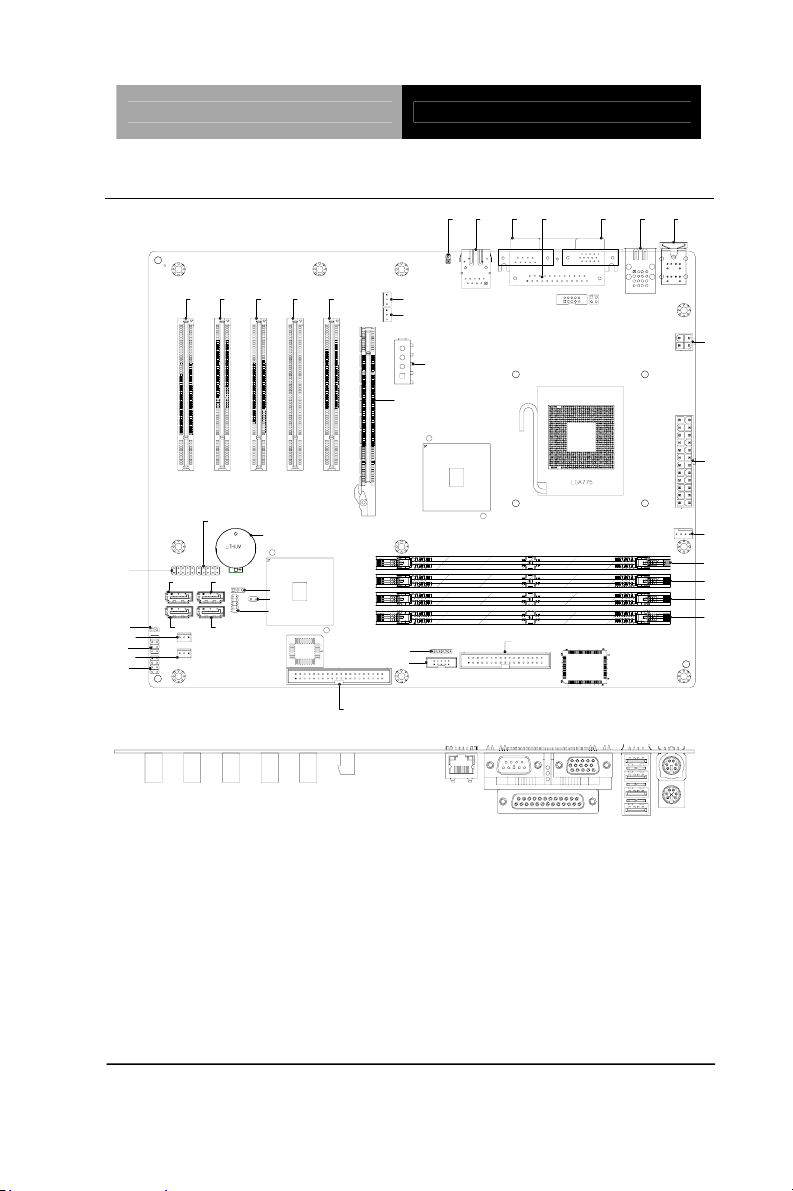
2.2 Location of Connectors and Jumpers
CN7
JP3
FAN4
FP1
FAN5
FP2
SATA1
SATA3
CN8
SATA2
SATA4
BAT1
JP5
JP1
CN9
PCI1PCI2PCI3PCI4PCI5
IDE1
IR1
COM2
FAN3
FAN2
GPCIE1
CN14
CN1
LAN1
COM1
FDD1
LPT1
VGA1
CN3
KM1
ATX2
ATX1
FAN1
DIMM1
DIMM2
DIMM3
DIMM4
Chapter 2 Quick Installation Guide 2-3
Page 16
Industrial Motherboard IMBA-880 Rev.B
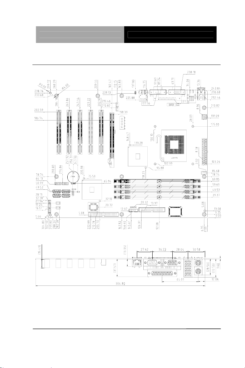
2.3 Mechanical Drawing
Chapter 2 Quick Installation Guide 2-4
Page 17
Industrial Motherboard IMBA-880 Rev.B
2.4 List of Jumpers
The board has a number of jumpers that allow you to configure your
system to suit your application.
The table below shows the function of each of the board's jumpers:
Label Function JP1 Clear CMOS
JP3 CFD Master/ Slave Selection
JP5 CFD Power Selection
2.5 List of Connectors
The board has a number of connectors that allow you to configure
your system to suit your application. The table below shows the
function of each board's connectors:
Label Function
FP1 Front Panel Connector 1
FP2 Front Panel Connector 2
ATX1 24-pin ATX Power
ATX2 4-pin ATX Power +12V Connector
DIMM1~4 DIMM Slot
GPCIE1
VGA1 VGA Display Connector
IDE1 EIDE Connector
SATA1~4 SATA Connector
PCI1~5 PCI Slot
PCI-Express[x16] Graphics Slot
Chapter 2 Quick Installation Guide 2-5
Page 18

Industrial Motherboard IMBA-880 Rev.B
KM1 PS/2 Keyboard/Mouse Connector
LAN1 10/100 Base-TX Ethernet Connector
CN1 LAN 1 Active LED Connector
CN3 USB Connector 90D X 4
CN7~8 USB Connector
CN9 AC97 Connector
FDD1 Floppy Connector
COM1 RS-232/422/485 Serial Port Connector
COM2 RS-232/422/485 Serial Port Connector
LPT1 LPT Port Connector
IR1 IrDA Connector
FAN1 4-pin Fan Connector
FAN2~5 3-pin Fan Connector
CN14 4-pin Power Connector
Chapter 2 Quick Installation Guide 2-6
Page 19

Industrial Motherboard IMBA-880 Rev.B
2.6 Setting Jumpers
You configure your card to match the needs of your application by
setting jumpers. A jumper is the simplest kind of electric switch. It
consists of two metal pins and a small metal clip (often protected by
a plastic cover) that slides over the pins to connect them. To “close”
a jumper you connect the pins with the clip.
To “open” a jumper you remove the clip. Sometimes a jumper will
have three pins, labeled 1, 2 and 3. In this case you would connect
either pins 1 and 2 or 2 and 3.
3
2
1
Open Closed Clo s ed 2-3
A pair of needle-nose pliers may be helpful when working with
jumpers.
If you have any doubts about the best hardware configuration for
your application, contact your local distributor or sales
representative before you make any change.
Generally, you simply need a standard cable to make most
connections.
Chapter 2 Quick Installation Guide 2-7
Page 20

Industrial Motherboard IMBA-880 Rev.B
2.7 CMOS Selection (JP1)
JP1 Function
Open Normal (Default)
Close Clear CMOS
2.8 CF Master/ Slave Selection (JP3)
JP3 Function
Open Master (Default)
Close Slave
2.9 CF Power Selection (JP5)
JP5 Function
1-2 +5V (Default)
2-3 +3.3V
2.10 Front Panel Connector (FP1)
Pin Signal Pin Signal
1 Power On Button (+) 2 Reset Switch (+)
3 Power On Button (-) 4 Reset Switch (-)
5 IDE LED (+) 6 Power LED (+)
7 IDE LED (-) 8 Power LED (-)
2.11 Front Panel Connector (FP2)
Pin Signal Pin Signal
1 External Speaker(+) 2 KeyBoard Lock (+)
3 N.C 4 GND
5 Internal Buzzer(-) 6 I2C Bus SMB Clock
7 External Speaker(-) 8 I2C Bus SMB Data
Note: Internal Buzzer enable: Close Pin 5,7
Chapter 2 Quick Installation Guide 2-8
Page 21

Industrial Motherboard IMBA-880 Rev.B
2.12 LAN LED Connector (CN1)
Pin Signal Pin Signal
1 Link_LED(-) 2 Active_LED(+)
2.13 USB Connector (CN7, CN8)
Pin Signal Pin Signal
1 +5V 2 GND
3 USBD1- 4 GND
5 USBD1+ 6 USBD2+
7 GND 8 USBD29 GND 10 +5V
2.14 AC97 Connector (CN9)
Pin Signal Pin Signal
1 AC_RST- 2 AC_SYNC
3 AC_DAIN2 4 AC_DAOUT
5 GND 6 AC_BCLK
7 GND 8 +5V
9 Lock 10 +3.3V
2.15 RS-232/422/485 Serial Port Connector (COM2)
Pin Signal Pin Signal
1 DCD(422TXD-/485DATA-) 2 RXD(422RXD+)
3 TXD(422TXD+/485DATA+) 4 DTR(422RXD-)
5 GND 6 DSR
7 RTS 8 CTS
9 RI 10 N.C
Chapter 2 Quick Installation Guide 2-9
Page 22

Industrial Motherboard IMBA-880 Rev.B
2.16 IrDA Connector (IR1)
Pin Signal
1 +5V
2 N.C
3 IRRX
4 GND
5 IRTX
6 N.C
2.17 Fan Connector (FAN1)
Pin Signal
1 GND
2 +12V
3 Speed Sense
4 Speed CTRL
2.18 FAN Connector (FAN2~5)
Pin Signal
1 GND
2 +12V
3 Speed Sense
2.19 4-Pin Power Connector (CN14)
Pin Signal
1 +5V
2 GND
3 GND
4 +12V
Chapter 2 Quick Installation Guide 2-10
Page 23

Industrial Motherboard IMBA-880 Rev.B
Below Table for China RoHS Requirements
产品中有毒有害物质或元素名称及含量
AAEON Main Board/ Daughter Board/ Backplane
有毒有害物质或元素
部件名称
印刷电路板
及其电子组件
外部信号
连接器及线材
O:表示该有毒有害物质在该部件所有均质材料中的含量均在
SJ/T 11363-2006 标准规定的限量要求以下。
X:表示该有毒有害物质至少在该部件的某一均质材料中的含量超出
SJ/T 11363-2006 标准规定的限量要求。
备注:此产品所标示之环保使用期限,系指在一般正常使用状况下。
铅
(Pb)汞 (Hg)镉 (Cd)
× ○ ○ ○ ○ ○
× ○ ○ ○ ○ ○
六价铬
(Cr(VI))
多溴联苯
(PBB)
多溴二苯醚
(PBDE)
Chapter 2 Quick Installation Guide 2-11
Page 24

Industrial Motherboard IMBA-880 Rev.B
Chapter
3
CPU, Heatsink and
Fan Installation
Chapter 3 CPU, Heatsink and Fan Installation 3-1
Page 25

Industrial Motherboard IMBA-880 Rev.B
3.1 CPU installation and motherboard handling
Note: When integrating a Pentium 4 processor-based system, be sure to take the
proper electrostatic discharge (ESD) precautions.
Caution: Please follow the steps below to ensure proper installation of your
processor. Failure to follow these instructions may result in damage to your CPU
and/or your motherboard.
Retention
tab
Load
lever
Protective Cover
Step 1: (Socket Preparation)
Note: Visually inspect to ensure that the socket protective cover is present and
securely fastened.
1. Opening the Socket:
Note: Hold corner of the load plate while opening and closing the load
lever. This will prevent the bounce back of the load plate which can
cause bent contacts.
a. Disengage the Load Lever by pressing down and
out on the hook allowing the lever to clear the
Retention Tab and rotate to the fully open position.
Chapter 3 CPU, Heatsink and Fan Installation 3-2
Page 26

Industrial Motherboard IMBA-880 Rev.B
b. Rotate Load Plate to fully open position
.
c. Remove the Protective Cover
Caution: Do not touch the Socket Contacts. This may result in damage to the
contacts.
Note: Visually inspect the contact area for bent contacts and foreign material.
Chapter 3 CPU, Heatsink and Fan Installation 3-3
Page 27

Industrial Motherboard IMBA-880 Rev.B
Step 2: (Processor Handling)
Note: Handle Processor by substrate edges only.
Caution: Do not touch processor contacts at any time
a. Remove processor from shipping media by
grasping substrate edges only
b. Visually inspect the processor gold pad array for
presence of foreign material. If foreign material is
present the pads may be wiped clean with a
lint-free cloth and isopropyl alcohol.
c. Locate the connector 1 indicator and the two
orientation notches. (See photo)
Chapter 3 CPU, Heatsink and Fan Installation 3-4
Page 28

Industrial Motherboard IMBA-880 Rev.B
Y
Step 3: (Positioning the CPU into socket)
a. Grasp the processor with your thumb and
forefinger on the edges with the orientation notches.
The socket has cut-outs for your fingers when
handled in this orientation.
b. Carefully place the CPU into the socket with a
purely vertical motion.
c. Verify that the CPU is in the socket body and
properly mated to the orientation keys.
The Alignment
Key is for you to
check if the CPU
is aligned with the
CPU notch
properly.
ellow
Triangle
Mark
Chapter 3 CPU, Heatsink and Fan Installation 3-5
Page 29

Industrial Motherboard IMBA-880 Rev.B
d. Close the upper plate (A), place the load lever back
to the original position and tightly wedge the lever
into the fastening tab. (B)
A
B
Step 4: (Heatsink/ Fan Installation).
a. Place bottom bracket underneath the socket making
sure that threaded socket is aligned with the holes in
the motherboard.
Chapter 3 CPU, Heatsink and Fan Installation 3-6
Page 30

Industrial Motherboard IMBA-880 Rev.B
b. Viewing the board again from the topside make sure
the bracket on the solder side has not shifted from
its position. Daub thermal compound on the CPU.
c. Place the Heatsink on the top of CPU. Please make
sure that the four screws are aligned with the holes
on the board.
Chapter 3 CPU, Heatsink and Fan Installation 3-7
Page 31

Industrial Motherboard IMBA-880 Rev.B
d. Fasten the four screws. First fasten the two screws
(yellow) and then fasten the two screws (red) in
sequence to secure the heatsink in place.
e. Connect the CPU fan cable to the power connector
labeled FAN1 on the board.
Chapter 3 CPU, Heatsink and Fan Installation 3-8
Page 32

Industrial Motherboard IMBA-880 Rev.B
Chapter
4
BIOS Setup
Award
Chapter 4 Award BIOS Setup 4-1
Page 33

Industrial Motherboard IMBA-880 Rev.B
4.1 System Test and Initialization
These routines test and initialize board hardware. If the routines
encounter an error during the tests, you will either hear a few short
beeps or see an error message on the screen. There are two kinds
of errors: fatal and non-fatal. The system can usually continue the
boot up sequence with non-fatal errors. Non-fatal error messages
usually appear on the screen along with the following instructions:
Press <F1> to RESUME
Write down the message and press the F1 key to continue the boot
up sequence.
System configuration verification
These routines check the current system configuration against the
values stored in the CMOS memory. If they do not match, the
program outputs an error message. You will then need to run the
BIOS setup program to set the configuration information in memory.
There are three situations in which you will need to change the
CMOS settings:
1. You are starting your system for the first time
2. You have changed the hardware attached to your system
3. The CMOS memory has lost power and the configuration
information has been erased.
The IMBA-880 Rev.B CMOS memory has an integral lithium battery
backup for data retention. However, you will need to replace the
complete unit when it finally runs down.
Chapter 4 Award BIOS Setup 4-2
Page 34

Industrial Motherboard IMBA-880 Rev.B
4.2 Award BIOS Setup
Awards BIOS ROM has a built-in Setup program that allows users
to modify the basic system configuration. This type of information is
stored in battery-backed CMOS RAM so that it retains the Setup
information when the power is turned off.
Entering Setup
Power on the computer and press <Del> immediately. This will
allow you to enter Setup.
Standard CMOS Features
Use this menu for basic system configuration. (Date, t ime, IDE,
etc.)
Advanced BIOS Features
Use this menu to set the advanced features available on your
system.
Chapter 4 Award BIOS Setup 4-3
Page 35

Industrial Motherboard IMBA-880 Rev.B
Advanced Chipset Features
Use this menu to change the values in the chipset registers and
optimize your system performance.
Integrated Peripherals
Use this menu to specify your settings for integrated peripherals.
(Primary slave, secondary slave, keyboard, mouse etc.)
Power Management Setup
Use this menu to specify your settings for power management.
(HDD power down, power on by ring, KB wake up, etc.)
PnP/PCI Configurations
This entry appears if your system supports PnP/PCI.
PC Health Status
This menu allows you to set the shutdown temperature for your
system.
Frequency/Voltage Control
Use this menu to specify your settings for auto detect DIMM/PCI
clock and spread spectrum.
Load Fail-Safe Defaults
Use this menu to load the BIOS default values for the
minimal/stable performance for your system to operate.
Load Optimized Defaults
Use this menu to load the BIOS default values that are factory
settings for optimal performance system operations. While AWARD
Chapter 4 Award BIOS Setup 4-4
Page 36

Industrial Motherboard IMBA-880 Rev.B
has designated the custom BIOS to maximize performance, the
factory has the right to change these defaults to meet their needs.
Set Supervisor/User Password
Use this menu to set Supervisor/User Passwords.
Save and Exit Setup
Save CMOS value changes to CMOS and exit setup.
Exit Without Saving
Abandon all CMOS value changes and exit setup.
You can refer to the "AAEON BIOS Item Description.pdf" file in
the CD for the meaning of each setting in this chapter.
Chapter 4 Award BIOS Setup 4-5
Page 37

Industrial Motherboard IMBA-880 Rev.B
Chapter
5
Installation
Driver
Chapter 5 Driver Installation 5-1
Page 38

Industrial Motherboard IMBA-880 Rev.B
The IMBA-880 Rev.B comes with an AutoRun CD-ROM that
contains all drivers and utilities that can help you to install the driver
automatically.
Insert the driver CD, the driver CD-title will auto start and show the
installation guide. If not, please follow the sequence below to install
the drivers.
Follow the sequence below to install the drivers:
Step 1 – Install INF Driver
Step 2 – Install VGA Driver
Step 3 – Install LAN Driver
Step 4 – Install Audio Driver
®
USB 2.0 Drivers are available for download using Windows
Update for both Windows
information regarding USB 2.0 support in Windows
Windows
®
2000, please visit www.microsoft.com/hwdev/usb/
®
XP and Windows® 2000. For additional
®
XP and
Please read instructions below for further detailed installation s.
Chapter 5 Driver Installation 5-2
Page 39

Industrial Motherboard IMBA-880 Rev.B
5.1 Installation:
Insert the IMBA-880 Rev.B CD-ROM into the CD-ROM drive. And
install the drivers from Step 1 to Step 4 in order.
Step 1 – Install INF Driver
1. Click on the Step 1-INF folder and select the OS your
system is
2. Double click on the .exe file
3. Follow the instructions that the window shows
4. The system will help you install the driver automatically
Step 2 – Install VGA Driver
1. Click on the Step 2-VGA folder and select the OS your
system is
2. Double click on the .exe file
3. Follow the instructions that the window shows
4. The system will help you install the driver automatically
Step 3 –Install LAN Driver
1. Click on the Step 3-LAN folder and double click on the
Autorun file
2. Follow the instructions that the window shows
3. The system will help you install the driver automatically
Chapter 5 Driver Installation 5-3
Page 40

Industrial Motherboard IMBA-880 Rev.B
Step 4 – Install Audio Driver
1. Click on the Step 4-AUDIO folder and double click on the
wdm_a371 file
2. Follow the instructions that the window shows
3. The system will help you install the driver automatically
Chapter 5 Driver Installation 5-4
Page 41

Industrial Motherboard IMBA-880 Rev.B
A
Appendix
Programming the
Watchdog Timer
Appendix A Programming the Watchdog Timer A-1
Page 42

Industrial Motherboard IMBA-880 Rev.B
A.1 Programming
IMBA-880 Rev.B utilizes W83627EHG chipset as its watchdog
timer controller.
Below are the procedures to complete its configuration and the
AAEON intial watchdog timer program is also attached based on
which you can develop customized program to fit your application.
Configuring Sequence Description
Unlock W83627EHG
Select register of
watchdog timer
Enable the function of
the watchdog timer
Use the function of the
watchdog timer
Lock W83627EHG
There are three steps to complete the configuration setup:
(1) Enter the W83627EHG config Mode
(2) Modify the data of configuration registers
Appendix A Programming the Watchdog Timer A-2
Page 43

Industrial Motherboard IMBA-880 Rev.B
(3) Exit the W83627EHG config Mode. Undesired result may
occur if the config Mode is not exited normally.
(1) Enter the W83627EHG config Mode
To enter the W83627EHG config Mode, two special I/O write
operations are to be performed during Wait for Key state. To
ensure the initial state of the key-check logic, it is necessary to
perform two write operations to the Special Address port (2EH).
The different enter keys are provided to select configuration ports
(2Eh/2Fh) of the next step.
Address Port Data Port
87h,87h: 2Eh 2Fh
(2) Modify the Data of the Registers
All configuration registers can be accessed after entering the config
Mode. Before accessing a selected register, the content of Index
07h must be changed to the LDN to which the register belongs,
except some Global registers.
(3) Exit the W83627EHG config Mode
The exit key is provided to select configuration ports (2Eh/2Fh) of
the next step.
Address Port Data Port
0aah: 2Eh 2Fh
WatchDog Timer Register I (Index=F5h, Default=00h)
CRF5 (PLED mode register. Default 0 x 00)
Bit 7-6 : select PLED mode
= 00 Power LED pin is tri-stated.
= 01 Power LED pin is drived low.
Appendix A Programming the Watchdog Timer A-3
Page 44

Industrial Motherboard IMBA-880 Rev.B
= 10 Power LED pin is a 1Hz toggle pulse
with 50 duty cycle.
= 11 Power LED pin is a 1/4Hz toggle pulse
with 50 duty cycle.
Bit 5-4 : Reserved
Bit 3 : select WDTO count mode.
= 0 second
= 1 minute
Bit 2 : Enable the rising edge of keyboard Reset
(P20) to force Time-out event.
= 0 Disable
= 1 Enable
Bit 1-0 : Reserved
WatchDog Timer Register II (Index=F6h, Default=00h)
Bit 7-0 = 0 x 00 Time-out Disable
= 0 x 01 Time-out occurs after 1
second/minute
= 0 x 02 Time-out occurs after 2
second/minutes
= 0 x 03 Time-out occurs after 3
second/minutes
………………………………..
= 0 x FF Time-out occurs after 255
second/minutes
Appendix A Programming the Watchdog Timer A-4
Page 45

Industrial Motherboard IMBA-880 Rev.B
WatchDog Timer Register III (Index=F7h, Default=00h)
Bit 7 : Mouse interrupt reset Enable or Disable
= 1 Watchdog Timer is reset upon a
Mouse interrupt
= 0 Watchdog Timer is not affected by
Mouse interrupt
Bit 6 : Keyboard interrupt reset Enable or
Disable
= 1 Watchdog Timer is reset upon a
Keyboard interrupt
= 0 Watchdog Timer is not affected by
Keyboard interrupt
Bit 5 : Force Watchdog Timer Time-out. Write
Only
= 1 Force Watchdog Timer time-out
event: this bit is self-clearing
Bit 4 : Watchdog Timer Status. R/W
= 1 Watchdog Timer time-out occurred
= 0 Watchdog Timer counting
Bit 3-0 : These bits select IRQ resource for
Watchdog. Setting of 2 selects SMI.
Appendix A Programming the Watchdog Timer A-5
Page 46

Industrial Motherboard IMBA-880 Rev.B
A.2 W83627EHG Watchdog Timer Initial Program
Example: Setting 10 sec. as Watchdog timeout interval
;///////////////////////////////////////////////////////////////////////////////////////////////
Mov dx,2eh ;Enter W83627EHG config mode
Mov al,87h (out 87h to 2eh twice)
Out dx,al
Out dx,al
;///////////////////////////////////////////////////////////////////////////////////////////////
Mov al,07h
Out dx,al
Inc dx
Mov al,08h ;Select Logical Device 8 (GPIO Port
2)
Out dx,al
;///////////////////////////////////////////////////////////////////////////////////////////////
Dec dx
Mov al,30h ;CR30 (GP20~GP27)
Out dx,al
Inc dx
Mov al,01h ;Activate GPIO2
Out dx,al
Appendix A Programming the Watchdog Timer A-6
Page 47

Industrial Motherboard IMBA-880 Rev.B
;///////////////////////////////////////////////////////////////////////////////////////////////
Dec dx
Mov al,0f5h ;CRF5 (PLED mode register)
Out dx,al
Inc dx
In al,dx
And al,not 08h ;Set second as counting unit
Out dx,al
;///////////////////////////////////////////////////////////////////////////////////////////////
Dec dx
Mov al,0f6h ; CRF6
Out dx,al
Inc dx
Mov al,10 ;Set timeout interval as 10 sec.
Out dx,al
;///////////////////////////////////////////////////////////////////////////////////////////////
Dec dx ;Exit W83627EHG config mode
Mov al,0aah (out 0aah to 2eh once)
Out dx,al
;///////////////////////////////////////////////////////////////////////////////////////////////
Appendix A Programming the Watchdog Timer A-7
Page 48

Industrial Motherboard IMBA-880 Rev.B
Appendix
B
I/O Information
Appendix B I/O Information B - 1
Page 49

Industrial Motherboard IMBA-880 Rev.B
B.1 I/O Address Map
Appendix B I/O Information B - 2
Page 50

Industrial Motherboard IMBA-880 Rev.B
B.2 1st MB Memory Address Map
B.3 IRQ Mapping Chart
Appendix B I/O Information B - 3
Page 51

Industrial Motherboard IMBA-880 Rev.B
B.4 DMA Channel Assignments
Appendix B I/O Information B - 4
Page 52

Industrial Motherboard IMBA-880 Rev.B
x Appendi
C
Mating Connector
Appendix C Mating Connector C - 1
Page 53

Industrial Motherboard IMBA-880 Rev.B
C.1 List of Mating Connectors and Cables
The table notes mating connectors and available cables.
Function
Label
Mating Connector Connector
Vendor Model no
Available
Cable
Cable P/N
IDE1 IDE
Connector
SATA1,3 SATA
Connector
SATA2,4 SATA
Connector
FDD1 Floppy
Connector
LPT1 Parallel Port
Connector
FP1
FP2
CN1 LAN LED
CN3 QUAD USB
CN7
CN8
CN9 Audio Pin
CN14 4Pin Power
ATX1 ATX External
ATX2 4P Power
Front Panel
Connector
Connector
Connector
USB Pin
Header
Header
Connector
5VSB
Connector
Connnector
Catch
Electronics
TECHBEST 161S01-029
TECHBEST 161S01-025A SATA
Catch
Electronics
FOXCONN DM11351-H
JIH VEI
Electronics
JIH VEI
Electronics
Techbest
Electronics
JIH VEI
Electronics
JIH VEI
Electronics
HO-BASE
Technology
Catch
Electronics
Catch
Electronics
1137-020-40
SA
A-L
1137-000-34
SA
5W3-4F
21B22564-X
XS10B-01G
-6/3-VXX
21B12564-X
XS10B-01G
-6/3
KS-004-ATB
-10
21B22564-X
XS10B-01G
-6/3-VXX
21N22050-1
0S10B-01G4/2.8-V1-G
5082A-WS-4 N/A
1121-700-24S N/A
1121-700-04S N/A
IDE Cable 1701400453
SATA
Cable
Cable
Floppy
Disk Drive
Cable
N/A
N/A
N/A
N/A
USB
Cable
N/A
1709070780
1709070780
1701340704
1709100204
Appendix C Mating Connector C - 2
Page 54

Industrial Motherboard IMBA-880 Rev.B
FAN1 FAN
Connector
FAN2~
FAN5
LAN1 Ethernet
IR1 IrDA
KM1 Mini-Din
COM1 Serial Port 1
COM2 Serial Port 2
VGA1 CRT Display
FAN
Connector
Connector
Connector
PS/2
Connector
Connector
Box Header
Connector
Catch
1190-700-042 N/A
Electronics
Catch
1190-700-03S N/A
Electronics
BOTHHAND LU1T516-43
LF
JIH VEI
Electronics
21B12050-X
XS10B-01G
-4/2.8
FOXCONN MH11061-P
36-4F
Astron DB6A-09-A
MGN1-R
Catch
1147-000-10S Serial
Electronics
Catch
Electronics
3125-000-1
5SB
N/A
N/A
N/A
N/A
1701100305
Port
Cable
N/A
Appendix C Mating Connector C - 3
 Loading...