

Page 1
Half-size SBC HSB-525I
HSB-525I
Intel® Atom D525 Processor
ISA Expansion Half-size SBC
Two 204-pin DDR3 800 SODIMM
3 SATA 3.0 Gb/s/ 1 IDE/ 1 CompactFlash™
5 USB2.0/ 2 COM/ 1 VGA/ 1 LVDS
HSB-525I Manual Rev.A 2nd Ed.
September 2011
Page 2

Half-size SBC HSB-525I
Copyright Notice
This document is copyrighted, 2011. All rights are reserved. The
original manufacturer reserves the right to make improvements to the
products described in this manual at any time without notice.
No part of this manual may be reproduced, copied, translated, or
transmitted in any form or by any means without the prior written
permission of the original manufacturer. Information provided in this
manual is intended to be accurate and reliable. However, the original
manufacturer assumes no responsibility for its use, or for any infringements upon the rights of third parties that may result from its
use.
The material in this document is for product information only and is
subject to change without notice. While reasonable efforts have been
made in the preparation of this document to assure its accuracy,
AAEON assumes no liabilities resulting from errors or omissions in
this document, or from the use of the information contained herein.
AAEON reserves the right to make changes in the product design
without notice to its users.
i
Page 3

Half-size SBC HSB-525I
Acknowledgments
All other products’ name or trademarks are properties of their
respective owners.
AMI is a trademark of American Megatrends Inc.
CompactFlash™ is a trademark of the Compact Flash
Association.
Intel
Microsoft Windows
ITE is a trademark of Integrated Technology Express, Inc.
IBM, PC/AT, PS/2, and VGA are trademarks of International
SoundBlaster is a trademark of Creative Labs, Inc.
All other product names or trademarks are properties of their
respective owners.
®
, and Atom are trademarks of Intel® Corporation.
®
is a registered trademark of Microsoft Corp.
Business Machines Corporation.
ii
Page 4

Half-size SBC HSB-525I
Packing List
Before you begin installing your card, please make sure that the
following materials have been shipped:
1 ATA100 Cable
1 USB Cable
1 Keyboard & Mouse Cable
1 Serial + Parallel Cable
1 Serial Cable
3 SATA Cables
1 Product CD (manual in PDF format and drivers)
1 HSB-525I CPU Card
If any of these items should be missing or damaged, please
contact your distributor or sales representative immediately.
iii
Page 5

Half-size SBC HSB-525I
Contents
Chapter 1 General Information
1.1 Introduction................................................................ 1-2
1.2 Features....................................................................1-3
1.3 Specification..............................................................1-4
Chapter 2 Quick Installation Guide
2.1 Safety Precautions.................................................... 2-2
2.2 Location of Connectors and Jumpers .......................2-3
2.3 Mechanical Drawing..................................................2-4
2.4 List of Jumpers..........................................................2-6
2.5 List of Connectors .....................................................2-7
2.6 Setting Jumpers ........................................................2-9
2.7 CF Selection (JP1).................................................... 2-10
2.8 LVDS Voltage Selection (JP2).................................. 2-10
2.9 LVDS Backlight Selection (JP3)................................2-10
2.10 Clear CMOS (JP4) ..................................................2-10
2.11 Auto Power Button (JP5)......................................... 2-10
2.12 Front Panel Connector (FP1)..................................2-11
2.13 Front Panel Connector (FP2)..................................2-11
2.14 USB Connector (USB1/2) ....................................... 2-11
2.15 RS-232/422/485 Serial Port Connector (COM2).....2-11
2.16 RS-232 Serial Port Connector (COM1)................... 2-12
2.17 Caseopen Connector (CN1).................................... 2-12
2.18 HD Audio Codec with Realtek ALC888 (Optional)
iv
Page 6

Half-size SBC HSB-525I
Connector (CN2)............................................................. 2-12
2.19 LVDS Connector (CN3)........................................... 2-12
2.20 Keyboard Connector (CN5)..................................... 2-13
2.21 LVDS Backlight Connector (CN6)...........................2-13
Chapter 3 AMI BIOS Setup
3.1 System Test and Initialization. ..................................3-2
3.2 AMI BIOS Setup........................................................3-3
Chapter 4 Driver Installation
4.1 Installation.................................................................4-3
Appendix A Programming The Watchdog Timer
A.1 Programming .........................................................A-2
A.2 W83627DHG Watchdog Timer Initial Program......A-2
Appendix B I/O Information
B.1 I/O Address Map....................................................B-2
B.2 Memory Address Map............................................B-3
B.3 IRQ Mapping Chart................................................B-4
B.4 DMA Channel Assignments .................................B-4
Appendix C Mating Connector
C.1 List of Mating Connectors and Cables.................. C-2
v
Page 7

Half-size SBC HSB-525I
Chapter
1
General
Information
Chapter 1 General Information 1- 1
Page 8

Half-size SBC HSB-525I
1.1 Introduction
The HSB-525I utilizes the Intel® Atom D525 and ICH8M chipset,
supporting Intel
®
Atom D525 processor with a FSB of 800MHz up to
1.8GHz. Offering two 204-pin DDR3 SODIMM sockets, the
HSB-525I supports DDR3 800 SODIMM system memory up to 4
GB.
This model offers a multitude of I/O including two COM ports and
five USB2.0 ports. To meet today’s increasing stora ge demands it
also supports three SATA 3.0 Gb/s, one T y pe II CompactFlash™ to
share IDE channel, and one ATA100 sockets. The flexible
expansion and storage makes the HSB-525I a great solution for
your vital applications.
In addition to the comprehensive COM and USB offering the
HSB-525I can also be configured with two Gigabit Ethernet ports to
meet the needs of high bandwidth connectivity. Supporting CRT &
LCD simultaneously along with the optional high definition audio
board, the HSB-525I is an ideal solution for demanding multimedia
based applications.
Chapter 1 General Information 1- 2
Page 9

Half-size SBC HSB-525I
1.2 Features
Intel® Atom™ D525 Processor
Intel
®
Atom™ D525 + ICH8M
204-Pin 800 MHz DDR3 SODIMM Memory x 2, Up to 4 GB
Gigabit Ethernet x 2
Intel
®
Atom™ D525 Integrated VGA, Shared Memory Up To
324MB With DVMT4.0.
Optional HD Codec Audio Daughter Board
SATA 3.0Gb/s x 3, CompactFlash™ Type 2 x 1, ATA100 x 1
USB2.0 x 5, RS-232/422/485 x 1, RS-232 x 1, Parallel x 1
ISA Expansion
+5V, +12V Operation, AT Power
Note: HSB-525I has to be operated with an ISA backplane to supply +5V,
+12V, and -12V power inputs to make COM1 work functionally.
Chapter 1 General Information 1- 3
Page 10

Half-size SBC HSB-525I
1.3 Specification
System
Form Factor ISA Half-size Board
CPU Onboard Intel
®
Atom™ D525
Processor up to 1.8GHz with a 1
MB L2 cache
System Memory Two 204-pin 800 MHz DDR3
SODIMM, up to 4 GB
Chipset Intel
®
Atom™D525 + Intel® ICH8M
Ethernet Realtek RTL 8111C x 2,
Gigabit Ethernet, RJ-45 x 2
Audio (Optional HD Audio Codec with Realtek
Daughter Board) ALC88 8
BIOS AMI Plug & Play SPI BIOS –
4 MB ROM
I/O Chip Winbond 83627DHG-P
Storage 40-pin IDE slot x 1 (Slave), SATA
3.0 Gb/s x 3,
SSD CompactFlash™ Type II
connector, shares IDE channel
(Master)
Watchdog Timer 1~255 steps, can be set with
software on Super I/O
RTC Internal RTC
Chapter 1 General Information 1- 4
Page 11

Half-size SBC HSB-525I
H/W Status Monitor Monitoring system temperature,
voltage, and cooling fan status
Battery Lithium battery
Power Requirement +5V, ±12V by ISA bus, onboard
4-pin power connector (+5V,
+12V)
Note: HSB-525I has to be operated with an ISA backplane.
Normally, onboard 4-pin power connector can supply power (+5V
and +12V) to operate the board. But the COM1 will need +5V and
±12V power supplied through the ISA bus.
Board Size 7.3”(L) x 4.8” (W)
(185mm x 122mm)
Gross Weight 0.71lb (0.3kg)
Operating Temperature 32
Storage Temperature -4
o
F~140oF(0oC~60oC)
o
F~158oF(-20oC~70oC)
Operating Humidity 10%~80%, non-condensing
EMI CE/FCC Class A
Display
Chipset Intel
Graphic Engine Intel
®
Atom™D525 + ICH8M
®
Atom™D525 with
integrated Graphics Core
Resolutions Up to 2048x1536 @ 60 Hz for
CRT; 1366x768 @ 60 Hz for
LCD
Output Interface VGA x 1, LVDS x 1
Chapter 1 General Information 1- 5
Page 12

Half-size SBC HSB-525I
I/O
Serial Port COM1: RS-232
COM2: RS-232/422/485
Parallel Port Supports SPP/EPP/ECP mode
Keyboard/Mouse
Keyboard/Mouse x 1
Universal Serial Bus USB2.0 x 5, 5x2-pin header x 2,
Type A x 1
Audio Audio Jack x 2
Ethernet RJ-45 x 2
Display VGA x 1, LVDS x 1
Chapter 1 General Information 1- 6
Page 13

Half-size SBC HSB-525I
Chapter
2
Quick
Inst
Chapter 2 Quick Installation Guide 2 - 1
allation
Guide
Page 14
Half-size SBC HSB-525I
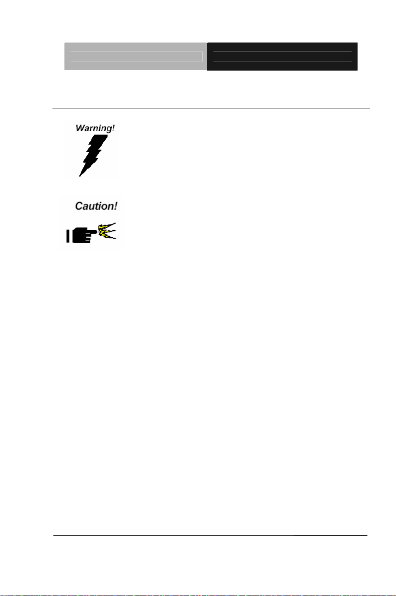
2.1 Safety Precautions
Always completely disconnect the power cord
from your board whenever you are working on
it. Do not make connections while the power is
on, because a sudden rush of power can
damage sensitive electronic components.
Always ground yourself to remove any static
charge before touching the board. Modern
electronic devices are very sensitive to static
electric charges. Use a grounding wrist strap at
all times. Place all electronic components on a
static-dissipative surface or in a static-shielded
bag when they are not in the chassis
Chapter 2 Quick Installation Guide 2 - 2
Page 15
Half-size SBC HSB-525I
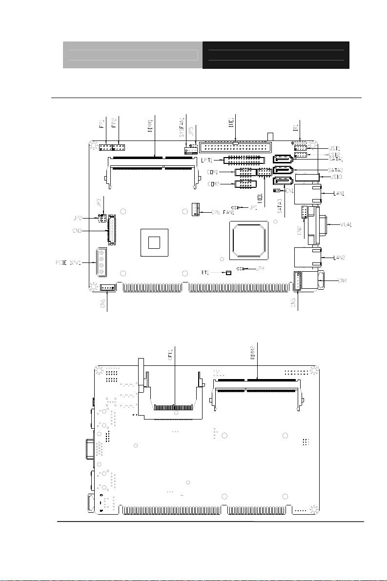
2.2 Location of Connectors and Jumpers
Component Side
Solder Side
Chapter 2 Quick Installation Guide 2 - 3
Page 16

Half-size SBC HSB-525I
2.3 Mechanical Drawing
Component Side
Chapter 2 Quick Installation Guide 2 - 4
Page 17

Half-size SBC HSB-525I
Solder Side
Chapter 2 Quick Installation Guide 2 - 5
Page 18

Half-size SBC HSB-525I
2.4 List of Jumpers
The board has a number of jumpers that allow you to configure your
system to suit your application.
The table below shows the function of each of the board's jumpers:
Jumpers
Label Function
JP1 CF Select
JP2 LCD Panel Voltage Selection
JP3 LCD Backlight Voltage Selection
JP4 Clear CMOS
JP5 Auto power Button
Chapter 2 Quick Installation Guide 2 - 6
Page 19

Half-size SBC HSB-525I
2.5 List of Connectors
The board has a number of connectors that allow you to configure your
system to suit your application. The table below shows the function of
each board's connectors:
Connectors
Label Function
FP1 Front Panel Connector 1
FP2 Front Panel Connector 2
VGA1 VGA Port Connector
COM2 RS-232/485/422 Serial Connector
COM1 RS-232 Serial Connector
CN1 Caseopen Pin Header
CN2
CN3 LVDS Connector
CN4 PS2 Keyboard/Mouse Connector
CN5 Keyboard Connector
CN6 LVDS Backlight Connector
LAN1 100/1000Base-TX Ethernet Connector
LAN2 100/1000Base-TX Ethernet connector
DIMM1 DDR3 SODIMM Slot
DIMM2 DDR3 SODIMM Slot
HD Audio Codec with Realtek ALC888
( Optional ) Connector
USB1 USB Connector
USB2 USB Connector
USB3 USB Connector
CPU_FAN1, 4-Pin CPU Fan Connector
Chapter 2 Quick Installation Guide 2 - 7
Page 20

Half-size SBC HSB-525I
SYS_FAN1 4-Pin System Fan Connector
PCIE_12V1 4-Pin ATX Power Connector
BT1 Battery
SATA1~SATA3 SATA Connector
SPI1 BIOS DEBUG PORT
IDE1 IDE Connector
LPT1 Parallel Port Connector
CFD1 CF Card Connector
Chapter 2 Quick Installation Guide 2 - 8
Page 21

Half-size SBC HSB-525I
2.6 Setting Jumpers
You configure your card to match the needs of your application by
setting jumpers. A jumper is the simplest kind of electric switch. It
consists of two metal pins and a small metal clip (often protected by a
plastic cover) that slides over the pins to connect them. To “close” a
jumper you connect the pins with the clip.
To “open” a jumper you remove the clip. Sometimes a jumper will have
three pins, labeled 1, 2 and 3. In this case you would connect either
pins 1 and 2 or 2 and 3.
3
2
1
Open Closed Closed 2-3
A pair of needle-nose pliers may be helpful when working with jumpers.
If you have any doubts about the best hardware configuration for your
application, contact your local distributor or sales representative before
you make any change.
Generally, you simply need a standard cable to make most
connections.
Chapter 2 Quick Installation Guide 2 - 9
Page 22

Half-size SBC HSB-525I
2.7 CF Selection (JP1)
JP1 Function
1-2 Master(Default)
2-3 Slave
2.8 LVDS Voltage Selection (JP2)
JP2 Function
1-2 +5V
2-3 +3.3V (Default)
2.9 LVDS Backlight Selection (JP3)
JP3 Function
Backlight Control
1-3 PWM Ctrl
3-5 Voltage Ctrl (Default)
Backlight Voltage
2-4 +5V
4-6 +12V (Default)
2.10 Clear CMOS (JP4)
JP4 Function
1-2 Protected (Default)
2-3 Clear
2.11 Auto Power Button (JP5)
JP5 Function
1-2 Auto power Button off
2-3 Auto power Button on (Default)
Chapter 2 Quick Installation Guide 2 - 10
Page 23

Half-size SBC HSB-525I
2.12 Front Panel Connector (FP1)
Pin Signal Pin Signal
1 Power On Button (+) 2 Reset Switch (+)
3 Power On Button (-) 4 Reset Switch (-)
5 HDD LED (+) 6 Power LED (+)
7 HDD LED (-) 8 Power LED (-)
2.13 Front Panel Connector (FP2)
Pin Signal Pin Signal
1 External Speaker (+) 2 Key Board Lock (+)
3 NC 4 GND
5 Internal Buzzer (-) 6 I2C Bus SMB Clock
7 External Speaker (-) 8 I2C Bus SMB Data
Note: Internal Buzzer enable: Close Pin 5,7
2.14 USB Connector (USB1/2)
Pin Signal Pin Signal
1 +5V 2 GND
3 USBD1- 4 GND
5 USBD1+ 6 USBD2+
7 GND 8 USBD29 GND 10 +5V
2.15 RS-232/422/485 Serial Port Connector (COM2)
Pin Signal Pin Signal
DCD
1
(422TXD-/485DATA-)
TXD
3
(422TXD+/485DATA+)
5 GND 6 DSR
Chapter 2 Quick Installation Guide 2 - 11
2 RXD (422RXD+)
4 DTR (422RXD-)
Page 24

Half-size SBC HSB-525I
7 RTS 8 CTS
9 RI 10 N.C
2.16 RS-232 Serial Port Connector (COM1)
Pin Signal Pin Signal
1 DCD 2 RXD
3 TXD 4 DTR
5 GND 6 DSR
7 RTS 8 CTS
9 RI 10 N.C
2.17 Caseopen Connector (CN1)
Pin Signal Pin Signal
1 CASEOPEN# 2 GND
2.18 HD Audio Codec with Realtek ALC888 (Optional) Connector
(CN2)
Pin Signal Pin Signal
1 RST 2 SYNC
3 SDIN 4 SDOUT
5 DET 6 BCLK
7 GND 8 +5V
9 N.C. 10 +3.3V
2.19 LVDS Connector (CN3)
Pin Signal Pin Signal
1 LVDS_BKLEN 2 LVDS_BKLCTL
3 PPVCC 4 GND
5 LVDS_TXLCLK# 6 LVDS_TXLCLK
7 PPVCC 8 GND
Chapter 2 Quick Installation Guide 2 - 12
Page 25

Half-size SBC HSB-525I
9 LVDS_TXL0# 10 LVDS_TXL0
11 LVDS_TXL1# 12 LVDS_TXL1
13 LVDS_TXL2# 14 LVDS_TXL2
15 LVDS_TXL3# 16 LVDS_TXL3
17 LVDS_DDCPDATA 18 LVDS_DDCPCLK
19 N.C 20 N.C
21 N.C 22 N.C
23 N.C 24 N.C
25 N.C 26 N.C
27 PPVCC 28 GND
29 N.C 30 N.C
2.20 Keyboard Connector (CN5)
Pin Signal
1 KBCLK
2 KBDATA
3 N.C
4 GND
5 VCC
2.21 LVDS Backlight Connector (CN6)
Pin Signal
1 LVDS Voltage select
2 LVDS Backlight control
3 GND
4 GND
5 LVDS Backlight Enable
Chapter 2 Quick Installation Guide 2 - 13
Page 26

Half-size SBC HSB-525I
Below Table for China RoHS Requirements
产品中有毒有害物质或元素名称及含量
AAEON Main Board/ Daughter Board/ Backplane
有毒有害物质或元素
部件名称
印刷电路板
及其电子组件
外部信号
连接器及线材
O:表示该有毒有害物质在该部件所有均质材料中的含量均在
SJ/T 11363-2006 标准规定的限量要求以下。
X:表示该有毒有害物质至少在该部件的某一均质材料中的含量超出
SJ/T 11363-2006 标准规定的限量要求。
备注:此产品所标示之环保使用期限,系指在一般正常使用状况下。
铅
(Pb)汞 (Hg)镉 (Cd)
× ○ ○ ○ ○ ○
× ○ ○ ○ ○ ○
六价铬
(Cr(VI))
多溴联苯
(PBB)
多溴二苯醚
(PBDE)
Chapter 2 Quick Installation Guide 2 - 14
Page 27

Half-size SBC HSB-525I
Chapter
3
AMI
BIOS Setup
Chapter 3 AMI BIOS Setup 3-1
Page 28

Half-size SBC HSB-525I
3.1 System Test and Initialization
These routines test and initialize board hardware. If the routines
encounter an error during the tests, you will either hear a few short
beeps or see an error message on the screen. There are two kinds
of errors: fatal and non-fatal. The system can usually continue the
boot up sequence with non-fatal errors.
System configuration verification
These routines check the current system configuration against the
values stored in the CMOS memory. If they do not match, the
program outputs an error message. You will then need to run the
BIOS setup program to set the configuration information in memory.
There are three situations in which you will need to change the
CMOS settings:
1. You are starting your system for the first time
2. You have changed the hardware attached to your system
3. The CMOS memory has lost power and the configuration
information has been erased.
The HSB-525I CMOS memory has an integral lithium battery
backup for data retention. However, you will need to replace the
complete unit when it finally runs down.
Chapter 3 AMI BIOS Setup 3-2
Page 29

Half-size SBC HSB-525I
3.2 AMI BIOS Setup
AMI BIOS ROM has a built-in Setup program that allows users to
modify the basic system configuration. This type of information is
stored in battery-backed CMOS RAM so that it retains the Setup
information when the power is turned off.
Entering Setup
Power on the computer and press <Del> or <F2> immediately. This
will allow you to enter Setup.
Main
Set the date, use tab to switch between date elements.
Advanced
Enable disable boot option for legacy network devices.
Chipset
host bridge parameters.
Boot
Enables/disable quiet boot option.
Security
Set setup administrator password.
Save&Exit
Exit system setup after saving the changes.
Chapter 3 AMI BIOS Setup 3-3
Page 30

Half-size SBC HSB-525I
Chapter
4
Driver
Inst
Chapter 4 Driver Installation 4-1
allation
Page 31

Half-size SBC HSB-525I
The HSB-525I comes with a CD-ROM that contains all drivers your
need.
Follow the sequence below to install the drivers:
Step 1 – Install Chipset Driver
Step 2 – Install VGA Driver
Step 3 – Install LAN Driver
Step 4 – Install Audio Driver
Please read following instructions for detailed installations.
Chapter 4 Driver Installation 4-2
Page 32

Half-size SBC HSB-525I
4.1 Installation:
Insert the HSB-525I CD-ROM into the CD-ROM Drive. And install
the drivers from Step 1 to Step 4 in order.
Step 1 – Install Chipset Driver
1. Click on the Step 1-Chipset folder and then double click
on the infinst_autol.exe
2. Follow the instructions that the window shows
3. The system will help you to install the driver automatically
Step 2 – Install VGA Driver
1. Click on the Step 2-Graphics Driver folder and select
the OS your system is
2. Double click on the .exe file located in each OS folder
3. Follow the instructions that the window shows
4. The system will help you to install the driver automatically
Step 3 – Install LAN Driver
1. Click on the Step 3-LAN folder and select the OS your
system is
2. Double click on .exe file located in each OS folder
3. Follow the instructions that the window shows
4. The system will help you to install the driver automatically
Step 4 – Install Audio Driver
1. Click on the Step 4-Audio folder and select the OS your
system is
Chapter4 Drivers Installation 4-3
Page 33

Half-size SBC HSB-525I
2. Double click on .exe file located in each OS folder
3. Follow the instructions that the window shows
4. The system will help you to install the driver automatically
Chapter 4 Driver Installation 4-4
Page 34

Half-size SBC HSB-525I
A
Appendix
Programming the
W
atchdog Timer
Appendix A Programming the Watchdog Timer A-1
Page 35

Half-size SBC HSB-525I
A.1 Programming
HSB-525I utilizes W83627DHG-P chipset as its watchdog timer
controller.
Below are the procedures to complete its configuration and the
AAEON intial watchdog timer program is also attached based on
which you can develop customized program to fit your application.
Configuring Sequence Description
There are th
Unlock W83627DHG
Select register of
watchdog timer
Enable the function of
the watchdog timer
Use the function of the
watchdog timer
Lock W83627DHG
ree steps to complete the configuration setup:
(1) Enter the W83627DHG config Mode
(2) Modify the data of configuration registers
Appendix A Programming the Watchdog Timer A-2
Page 36

Half-size SBC HSB-525I
(3) Exit the W83627DHG config Mode. Undesired result may
occur if the config Mode is not exited normally.
(1) Enter the W83627DHG config Mode
To enter the W83627DHG config Mode, two special I/O write
operations are to be performed during Wait for Key state. To
ensure the initial state of the key-check logic, it is necessary to
perform two write operations to the Special Address port (2EH).
The different enter keys are provided to select configuration ports
(2Eh/2Fh) of the next step.
Address Port Data Port
87h,87h: 2Eh 2Fh
(2) Modify the Data of the Registers
All configuration registers can be accessed after entering the config
Mode. Before accessing a selected register, the content of Index
07h must be changed to the LDN to which the register belongs,
except some Global registers.
(3) Exit the W83627DHG config Mode
The exit key is provided to select configuration ports (2Eh/2Fh) of
the next step.
Address Port Data Port
0aah: 2Eh 2Fh
WatchDog Timer Register I (Index=F5h, Default=00h)
CRF5 (PLED and KBC P20 Control Mode Register)
Bit 7-5 : select PLED mode
= 000 Power LED pin is driven high.
= 001 Power LED pin outputs 0.5Hz pulse
with 50% duty cycle.
Appendix A Programming the Watchdog Timer A-3
Page 37

Half-size SBC HSB-525I
= 010 Power LED pin is driven low.
= 011 Power LED pin outputs 2Hz pulse
with 50% duty cycle.
= 100 Power LED pin outputs 1Hz pulse
with 50% duty cycle.
= 101 Power LED pin outputs 4Hz pulse
with 50% duty cycle.
= 110 Power LED pin outputs 0.25Hz pulse
with 50% duty cycle.
=111 Power LED pin outputs 0.25Hz pulse
with 50% duty cycle..
Bit 4 : WDTO# count mode is 1000 times faster.
= 0 Disable.
= 1 Enable.
Bit 3 : select WDTO# count mode.
= 0 second
= 1 minute
Bit 2 : Enable the rising edge of keyboard Reset
(P20) to force Time-out event.
= 0 Disable
= 1 Enable
Bit 1 : Disable / Enable the WDTO# output low
pulse to the KBRST# pin (PIN60)
= 0 Disable
= 1 Enable
Bit 0 : Reserved.
Appendix A Programming the Watchdog Timer A-4
Page 38

Half-size SBC HSB-525I
WatchDog Timer Register II (Index=F6h, Default=00h)
Bit 7-0 = 0 x 00 Time-out Disable
= 0 x 01 Time-out occurs after 1
second/minute
= 0 x 02 Time-out occurs after 2
second/minutes
= 0 x 03 Time-out occurs after 3
second/minutes
………………………………..
= 0 x FF Time-out occurs after 255
second/minutes
WatchDog Timer Register III (Index=F7h, Default=00h)
Bit 7 : Mouse interrupt reset Enable or Disable
= 1 Watchdog Timer is reset upon a
Mouse interrupt
= 0 Watchdog Timer is not affected by
Mouse interrupt
Bit 6 : Keyboard interrupt reset Enable or
Disable
= 1 Watchdog Timer is reset upon a
Keyboard interrupt
= 0 Watchdog Timer is not affected by
Keyboard interrupt
Bit 5 : Force Watchdog Timer Time-out. Write
Only
Appendix A Programming the Watchdog Timer A-5
Page 39

Half-size SBC HSB-525I
= 1 Force Watchdog Timer time-out
event: this bit is self-clearing
Bit 4 : Watchdog Timer Status. R/W
= 1 Watchdog Timer time-out occurred
= 0 Watchdog Timer counting
Bit 3-0 : These bits select IRQ resource for
Watchdog. Setting of 2 selects SMI.
Appendix A Programming the Watchdog Timer A-6
Page 40

Half-size SBC HSB-525I
A.2 W83627DHG Watchdog Timer Initial Program
Example: Setting 10 sec. as Watchdog timeout interval
;///////////////////////////////////////////////////////////////////////////////////////////////
Mov dx,2eh ;Enter W83627DHG config mode
Mov al,87h (out 87h to 2eh twice)
Out dx,al
Out dx,al
;///////////////////////////////////////////////////////////////////////////////////////////////
Mov al,07h
Out dx,al
Inc dx
Mov al,08h ;Select Logical Device 8 (GPIO Port
2)
Out dx,al
;///////////////////////////////////////////////////////////////////////////////////////////////
Dec dx
Mov al,30h ;CR30 (GP20~GP27)
Out dx,al
Inc dx
Mov al,01h ;Activate GPIO2
Out dx,al
Appendix A Programming the Watchdog Timer A-7
Page 41

Half-size SBC HSB-525I
;///////////////////////////////////////////////////////////////////////////////////////////////
Dec dx
Mov al,0f5h ;CRF5 (PLED mode register)
Out dx,al
Inc dx
In al,dx
And al,not 08h ;Set second as counting unit
Out dx,al
;///////////////////////////////////////////////////////////////////////////////////////////////
Dec dx
Mov al,0f6h ; CRF6
Out dx,al
Inc dx
Mov al,10 ;Set timeout interval as 10 sec.
Out dx,al
;///////////////////////////////////////////////////////////////////////////////////////////////
Dec dx ;Exit W83627DHG config mode
Mov al,0aah (out 0aah to 2eh once)
Out dx,al
;///////////////////////////////////////////////////////////////////////////////////////////////
Appendix A Programming the Watchdog Timer A-8
Page 42

Half-size SBC HSB-525I
Appendix
B
I/O Information
Appendix B I/O Information B-1
Page 43

Half-size SBC HSB-525I
B.1 I/O Address Map
Appendix B I/O Information B-2
Page 44

Half-size SBC HSB-525I
B.2 Memory Address Map
Appendix B I/O Information B-3
Page 45

Half-size SBC HSB-525I
B.3 IRQ Mapping Chart
B.4 DMA Channel Assignments
Appendix B I/O Information B-4
Page 46

Half-size SBC HSB-525I
Appendix
C
Mating Connector
Appendix C Mating Connector C - 1
Page 47

Half-size SBC HSB-525I
C.1 List of Mating Connectors and Cables
The table notes mating connectors and available cables.
Connector
Label
IDE1 IDE
SATA1 SATA
SATA2 SATA
SATA3 SATA
LPT1 Parallel
COM1 Serial Port
COM2 Serial Port
USB1 USB Pin
USB2 USB Pin
USB3 USB
LAN1 Ethernet
LAN2 Ethernet
VGA1 CRT
Function
Connector
Connector
Connector
Connector
Port
Connector
Pin Header
Pin Header
Header
Header
Connector
Connector
Connector
Display
Connector
Mating Connector
Vendor Model no
Astron 26-03-220-1G-
ATB1-R
TECHBEST 161S01-025A SATA
TECHBEST 161S01-025A SATA
TECHBEST 161S01-025A SATA
Catch
Electronics
Astron 27-24041-210-
Astron 27-24041-210-
JIH VEI
Electronics
JIH VEI
Electronics
HO-BASE
BOTHHAND LA1T109D-A-
BOTHHAND LA1T109D-A-
Catch
Electronics
1147-000-26M LPT Cable 1701260307
1G-TB1-R
1G-TB1-R
21B22050-XX
S10B-01G-4/2
.8
21B22050-XX
S10B-01G-4/2
.8
KS-001V-ANW
D43 LF
D43 LF
3125-000-15S
B
Available
Cable
IDE Cable 17014004 53
Cable
Cable
Cable
Serial Port
Cable
Serial Port
Cable
USB Cable 1709100201
USB Cable 1709100201
N/A
N/A
N/A
N/A
Cable P/N
1709070800
1709070800
1709070800
1701100305
1701100305
Appendix C Mating Connector C - 2
Page 48

Half-size SBC HSB-525I
CFD1 CF Card
Connector
FP1 Front
Panel
Connector
FP2 Front
Panel
Connector
CN1 Caseopen
Connector
CN2 Audio Pin
Header
CN3 LVDS
Channel
Connector
CN4 PS2
Keyboard/
Mouse
Connector
CN5 KB Pin
Header
CN6 LVDS BKT
Ctrl
Connector
BT1 BAT
Connector
Comweal 60328226 N/A
JIH VEI
Electronics
21B22564-XX
S10B-01G-6/3
N/A
-VXX
JIH VEI
Electronics
21B22564-XX
S10B-01G-6/3
N/A
-VXX
JIH VEI
Electronics
JIH VEI
Electronics
21B12564-XX
S10B-01G-6/3
21N22050-10
S10B-01G-4/2
N/A
.8-V1-G
ECALL 0110-01-553-3
00
TECHBEST DN-508BS1-6-
L
JIH VEI
2503-H-5 N/A
KB/MS
Cable
1700060192
Electronics
Catch
1192-000-05S N/A
Electronics
Catch
120170002S N/A
Electronics
Appendix C Mating Connector C - 3
 Loading...