

Page 1

ETX CPU Module ETX- A55E
ETX-A55E
AMD G-Series Processors
DDR3L Memory
SATA x 2, PATA x 2, PCI x 4
USB 2.0 x 4, COM x 2, 8/16-bit ISA
CRT, HD Audio, I2C
18/24-bit Dual-Channel LVDS
st
ETX-A55E Rev. A Manual 1
July 28, 2015
Ed.
Page 2

ETX CPU Module ETX- A55E
Copyright Notice
This document is copyrighted, 2015. All rights are reserved. The
original manufact urer res erves t he r ight to m ake im provem ents to t he
products described in this manual at any time without notice.
No part of this manual may be reproduced, copied, translated, or
transmitted in any form or by any means without the prior written
permission of the or iginal manufacturer. Inform ation provided in this
manual is intended to be acc urate and reliable. However, the or iginal
manufacturer assumes no responsibility for its use, or for any infringements upon the rights of third parties that may result from its
use.
The material i n this document is for product information o nly and is
subject to change witho ut notice. W hile reas onable ef forts have bee n
made in the preparation of this document to assure its accuracy,
AAEON assumes no liabilities resulting from errors or omissions in
this document, or from the use of the information contained herein.
AAEON reserves the right to make changes in the product design
without notice to its users.
i
Page 3

ETX CPU Module ETX- A55E
Acknowledgments
All other products’ name or trademarks are properties of their
respective owners.
AMD is trademark of Advanced Micro Devices.
®
Microsoft Windows
ITE is a trademark of Integrated Technology Express, Inc.
IBM, PC/AT, PS/2, and VGA are trademarks of International
Business Machines Corporation.
All other product names or trademarks are properties of their
respective owners.
is a registered trademark of Microsoft Corp.
ii
Page 4

ETX CPU Module ETX- A55E
Packing List
Before you begin installing your card, please make sure that the
following materials have been shipped:
• DVD-ROM for manual (in PDF format) and drivers
• ETX-A55E Module
If any of these items are missing or damaged, please contact your
distributor or sales representative immediately.
iii
Page 5

ETX CPU Module ETX- A55E
部件名称
有毒有害物质或元素
铅
汞
镉
六价铬
多溴联苯
多溴二苯醚
印刷电路板
及其电子组件
× ○ ○ ○ ○ ○
外部信号
连接器及线材
× ○ ○ ○ ○ ○
O:表示该有毒有害物质在该部件所有均质材料中的含量均在
标准规定的限量要求以下。
:表示该有毒有害物质至少在该部件的某一均质材料中的含量超出
标准规定的限量要求。
备注:此产品所标示之环保使用期限,系指在一般正常使用状况下。
China RoHS Requirements
产品中有毒有害物质或元素名称及含量
AAEON Main Board/ Daughter Board/ Backplane
SJ/T 11363-2006
X
SJ/T 11363-2006
(Pb)
(Hg)
(Cd)
(Cr(VI))
(PBB)
(PBDE)
iv
Page 6

ETX CPU Module ETX- A55E
PCB & Other
O:The quantity of poison ous or haz ardous subst anc es or e lemen ts foun d in ea ch of t he
he quantity of poisonous or haz ardou s s ubs t ances or elements fo und i n at least one
applicable under normal usage only
China RoHS Requirements
Poisonous or Hazardous Substances or Elements in Products
AAEON Main Board/ Daughter Board/ Backplane
Poisonous or Hazardous Substances or Elements
Component
Components
Wires &
Connectors
for External
Connections
Mercury
Lead
(Pb)
(Hg)
X O O O O O○
X O O O O O
Cadmium
(Cd)
Hexavalent
Chromium
(Cr(VI))
Polybrominated
Biphenyls
(PBB)
Polybrominated
Diphenyl Ethers
(PBDE)
component's parts is below the SJ/T 11363-2006-stipulated requirement.
X: T
of the component's parts is beyond the SJ/T 11363-2006-stipulated requirement.
Note: The Environment Friendly Use Period as labeled on this product is
v
Page 7

ETX CPU Module ETX- A55E
Contents
Chapter 1 General Information
1.1 Introduction ....................................................................1-2
1.2 Features ........................................................................1-3
1.3 Specifications ................................................................1-4
Chapter 2 Quick Installation Guide
2.1 Safety Precautions ........................................................2-2
2.2 Mechanical Drawing ......................................................2-3
2.3 Block Diagram ...............................................................2-5
2.4 List of Connectors .........................................................2-6
2.4.1 RTC Battery Connector (CN1) .............................2-7
2.4.2 SPI ROM Flash Connector (CN2) .......................2-7
2.4.3 Fan Connector (CN4) ..........................................2-8
2.4.4 SATA Connector (CN5) .......................................2-8
2.4.5 SATA Connector (CN6) .......................................2-9
2.4.6 LCP Debug Port Connector (CN7) ....................2-10
2.4.7 ETX – X1 Connector (X1A)................................2-11
2.4.8 ETX – X2 Connector (X1B)................................2-11
2.4.9 ETX – X3 Connector (X1C) ...............................2-15
2.4.10 ETX – X4 Connector (X1D) .............................2-17
2.4.11 DDR3L SODIMM Connector (DIMM1) ...........2-19
2.5 List of Switches ..........................................................2-19
2.5.1 ATX/AT Mode & Clear CMOS Switch ..............2-21
vi
Page 8

ETX CPU Module ETX- A55E
Chapter 3 AMI BIOS Setup
3.1 System Test and Initialization. ......................................3-2
3.2 AMI BIOS Setup ............................................................3-3
Chapter 4 Driver Installation
4.1 Installation .....................................................................4-3
Appendix A Programming The Watchdog Timer
A.1 Programming ............................................................... A-2
A.2 W83627DHG Watchdog Timer Initial Program ............ A-8
Appendix B I/O Information
B.1 I/O Address Map ....................................................... B-2
B.2 Memory Address Map ............................................... B-4
B.3 IRQ Mapping Chart ................................................... B-5
B.4 DMA Channel Assignment ........................................ B-6
Appendix C AHCI Settings
C.1 Setting AHCI ............................................................. C-2
vii
Page 9

ETX CPU Module ETX- A55E
1
Chapter
General
Information
Chapter 1 General Information 1- 1
Page 10

ETX CPU Module ETX- A55E
1.1 Introduction
This User’s Manual contains all the essential information, such as
detailed descriptions and explanations on the product’s hardware
and software features (if any), its specifications, dimensions,
jumper/connector settings/definitions, and driver installation
instructions (if any), to facilitate users in setting up their product.
Users ma y ref er to the AAEON.com for the latest version of this
document.
Chapter 1 General Information 1- 2
Page 11

ETX CPU Module ETX- A55E
1.2 Features
AMD G-Series T-16R/T56N Processor
A55E Chipset
204-pin DDR3L 1066/1333 SODIMM Memory (up to 8 GB for
®
Windows
7 64-bit)
10/100 Ethernet x 1
CRT, 18/24-bit Dual-Channel LVDS
SATA x 2, PATA x 2, PCI x 4, SMBus x 5, PCI x 4, I2C
8/16-bit ISA
USB 2.0 x 4, COM x 2
Chapter 1 General Information 1- 3
Page 12

ETX CPU Module ETX- A55E
1.3 Specifications
System
Form Factor
Processor
ETX
AMD G-Series T16R Single-core 615 MHz
AMD G-Series T56N Dual-core 1.65 GHz
System Memory
204-pin DDR3L 1066/1333 MHz SODIMM
up to 8 GB
Chipset
Ethernet
BIOS
Wake On LAN
Watchdog Timer
H/W Status Monitoring
AMD A55E
®
Realtek
for 10/100 Base-TX
AMI UEFI BIOS
Yes
Super I/O
Super I/O
Expansion Interface 32-bit PCI x 4
SMBus x 1
I2C x 1
8/16-bit ISA
Power Requirement
DC 5V
Power Consumption (Typical) 10.7 W (T16R)
Chapter 1 General Information 1- 4
Page 13

ETX CPU Module ETX- A55E
24.2 W (T56N)
Board Size ETX, 114 x 95mm (4.5" x 3.74")
Gross Weight
Operating Temperature
Storage Temperature
Operation Humidity
Display
Chipset
Memory
Resolution
LCD Interface
I/O
0.2 kg (1.4 lb)
0 °C ~ 60 °C (32 °F ~ 140 °F)
-20°C ~ 70°C (-4°F ~ 158°F)
10 ~ 80% Relative Humidity,
Non-Condensing
AMD G-Series Integrated Graphics Engine
Shared Memory: 256 MB/ UMA
CRT up to 1920 x 1200
LVDS up to 1920 x 1200
18/24-bit Dual-Channel LVDS
Storage
USB
Serial Port
DI/O -
PATA x 2 (supports 2 devices)
SATA 6.0 Gb/s x 2
USB 2.0 x 4
RS-232 x 2
Chapter 1 General Information 1- 5
Page 14

ETX CPU Module ETX- A55E
PS/2 Port PS/2 Keyboard x 1
Mouse x 1
Audio HD Audio x 1
Chapter 1 General Information 1- 6
Page 15

ETX CPU Module
E T X - A 5 5 E
Chapter
2
Quick
Installation
Guide
Chapter 2 Quick Installation Guide 2-1
Page 16
ETX CPU Module
E T X - A 5 5 E
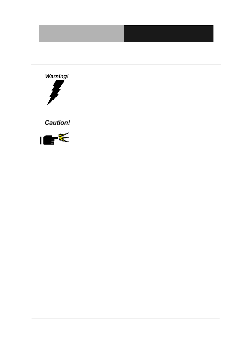
Always completely disconnect the power cord
from your board whenever you are working on
it. Do not make connections while the power is
on, because a sudden rush of power can
damage sensitive electronic components.
Always ground yourself to remove any static
charge before touching the board. Modern
electronic devices are very sensitive to static
electric charges. Use a grounding wrist strap at
all times. Place all electronic components on a
static-dissipative surface or in a static-shielded
bag when they are not in the chassis
2.1 Safety Precautions
Chapter 2 Quick Installation Guide 2-2
Page 17
ETX CPU Module
E T X - A 5 5 E
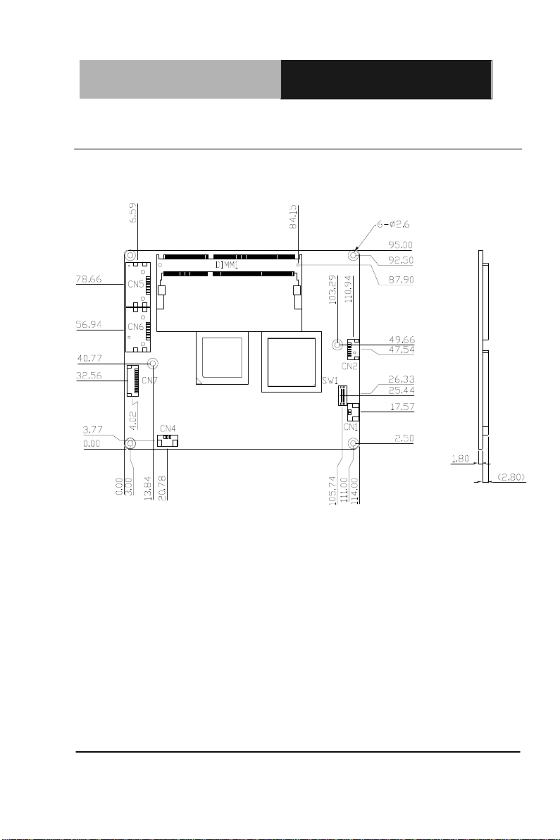
2.2 Mechanical Drawing
Component Side
Chapter 2 Quick Installation Guide 2-3
Page 18
ETX CPU Module
E T X - A 5 5 E
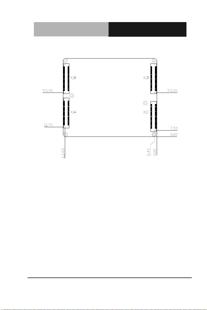
Solder Side
Chapter 2 Quick Installation Guide 2-4
Page 19

ETX CPU Module
E T X - A 5 5 E
2.3 Block Diagram
Chapter 2 Quick Installation Guide 2-5
Page 20

ETX CPU Module
E T X - A 5 5 E
Label
Function
CN1
RTC Battery Connector
CN2
BIOS SPI Rom Flash Connector
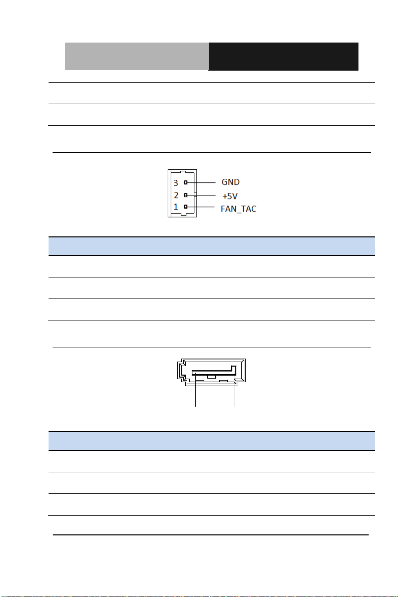
CN4
FAN Connector
CN5
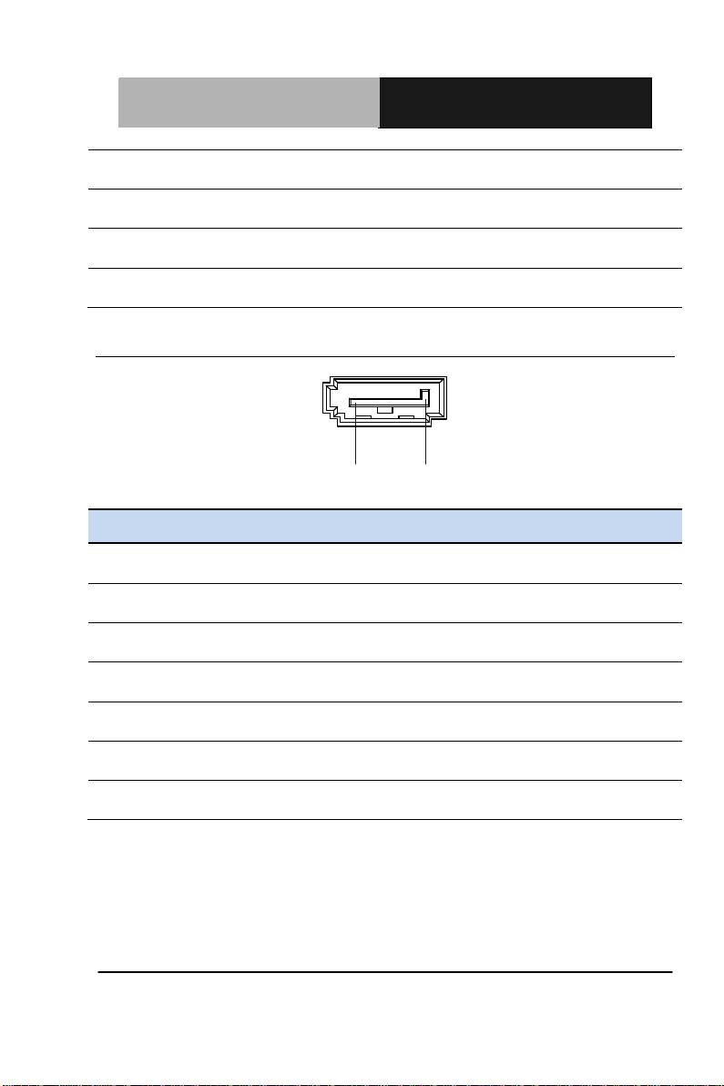
SATA Connector
CN6
SATA Connector
CN7
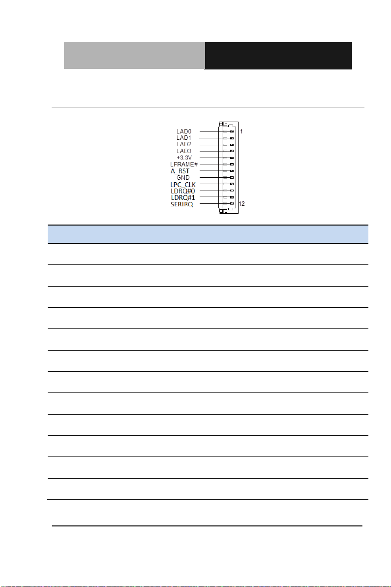
LPC Debug Port Connector
X1A
ETX - X1 Connector
X1B
ETX - X2 Connector
X1C
ETX - X3 Connector
X1D
ETX - X4 Connector
DIMM1
DDR3 SODIMM connector
2.4 List of Connectors
The board has a number of connectors that allow you to configure your
system to suit your application.
The table below shows the function of each of the board's jumpers:
Chapter 2 Quick Installation Guide 2-6
Page 21
ETX CPU Module
E T X - A 5 5 E
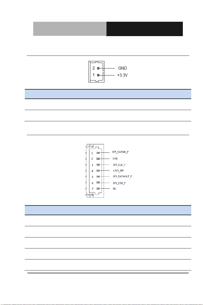
Pin
Pin Name
Signal Type
Signal level
1
RTCBAT
PWR
+3.3V
2
GND
GND
Pin
Pin Name
Signal Type
Signal level
1
SPI_DATAIN_F
I/O
3.3V
2
GND
GND 3
SPI_CLK_F
I/O
3.3V
4
+3V3_SPI
PWR
3.3V
5
SPI_DATAOUT_F
I/O
3.3V
2.4.1 RTC Battery Connector (CN1)
2.4.2 SPI Rom Flash Connector (CN2)
Chapter 2 Quick Installation Guide 2-7
Page 22
ETX CPU Module
E T X - A 5 5 E
6
SPI_CS#_F
I/O
3.3V 7 NC
Pin
Pin Name
Signal Type
Signal level
1
FAN_TAC
NA
2
+5V
PWR
+5V
3
GND
GND
Pin 1 Pin 7
Pin
Pin Name
Signal Type
Signal level
1
GND
GND 2
SATA_TX0_P_C
DIFF
3
SATA_TX0_N_C
DIFF
2.4.3 Fan Connector (CN4)
2.4.4 SATA Connector (CN5)
Chapter 2 Quick Installation Guide 2-8
Page 23
ETX CPU Module
E T X - A 5 5 E
4
GND
GND 5
SATA_RX0_N_C
DIFF
6
SATA_RX0_P_C
DIFF
7
GND
GND
Pin 1 Pin 7
Pin
Pin Name
Signal Type
Signal level
1
GND
GND
2
SATA_TX1_P_C
DIFF 3
SATA_TX1_N_C
DIFF 4
GND
GND 5
SATA_RX1_N_C
DIFF
6
SATA_RX1_P_C
DIFF
7
GND
GND
2.4.5 SATA Connector (CN6)
Chapter 2 Quick Installation Guide 2-9
Page 24
ETX CPU Module
E T X - A 5 5 E
Pin
Pin Name
Signal Type
Signal level
1
LAD0
I/O
+3.3V
2
LAD1
I/O
+3.3V
3
LAD2
I/O
+3.3V
4
LAD3
I/O
+3.3V
5
+3.3V
PWR
+3.3V
6
LFRAME#
IN 7
A_RST#
OUT
+3.3V
8
GND
GND
9
LPC_CLK
OUT 10
LDRQ#0
IN 11
LDRQ#1
IN 12
SERIRQ
I/O
+3.3V
2.4.6 LPC Debug Port Connector (CN7)
Chapter 2 Quick Installation Guide 2-10
Page 25

ETX CPU Module
E T X - A 5 5 E
Pin
Signal
Pin
Signal
1
GND
2
GND
3
PCI2_CLK33
4
PCI3_CLK33
5
GND
6
GND
7
PCI0_CLK33
8
PCI1_CLK33
9
PCI_REQ#3
10
PCI_GNT#3
11
PCI_GNT#2
12
N/C
13
PCI_REQ#2
14
PCI_GNT#1
15
PCI_REQ#1
16
N/C
17
PCI_GNT#0
18
N/C
19
+5V
20
+5V
21
SERIRQ
22
PCI_REQ#0
23
AD0
24
N/C
25
AD1
26
AD2
27
AD4
28
AD3
29
AD6
30
AD5
31
C/BE#0
32
AD7
33
AD8
34
AD9
35
GND
36
GND
37
AD10
38
LIN_L
39
AD11
40
MIC_IN
41
AD12
42
LIN_R
2.4.7 ETX – X1 Connector (X1A)
Chapter 2 Quick Installation Guide 2-11
Page 26

ETX CPU Module
E T X - A 5 5 E
43
AD13
44
ASVCC
45
AD14
46
LOUT_L
47
AD15
48
ASGND
49
C/BE#1
50
LOUT_R
51
+5V_EXT
52
+5V
53
PAR
54
SERR#
55
PERR#
56
N/C
57
PME#
58
USB_P2-
59
LOCK#
60
DEVSEL#
61
TRDY#
62
USB_P3-
63
IRDY#
64
STOP#
65
FRAME#
66
USB_P2+
67
GND
68
GND
69
AD16
70
C/BE#2
71
AD17
72
USB_P3+
73
AD19
74
AD18
75
AD20
76
USB_P0-
77
AD22
78
AD21
79
AD23
80
USB_P1-
81
AD24
82
C/BE#3
83
+5V
84
+5V
85
AD25
86
AD26
87
AD28
88
USB_P0+
89
AD27
90
AD29
Chapter 2 Quick Installation Guide 2-12
Page 27

ETX CPU Module
E T X - A 5 5 E
91
AD30
92
USB_P1+
93
PCI_RST#
94
AD31
95
INT#C
96
INT#D
97
INT#A
98
INT#B
99
GND
100
GND
Pin
Signal
Pin
Signal
1
GND
2
GND 3 SD14
4
SD15 5 SD13
6
MASTER#
7
SD12
8
DRQ7 9 SD11
10
DACK#7
11
SD10
12
DRQ6
13
SD9
14
DACK#6
15
SD8
16
DRQ5
17
MEMW#
18
DACK#5
19
MEMR#
20
DRQ0
21
SA17
22
DACK#0
23
SA18
24
IRQ14
25
SA19
26
IRQ15
27
SA20
28
IRQ12
29
SA21
30
IRQ11
31
SA22
32
IRQ10
2.4.8 ETX – X2 Connector (X1B)
Chapter 2 Quick Installation Guide 2-13
Page 28

ETX CPU Module
E T X - A 5 5 E
33
SA23
34
IOCS16#
35
GND
36
GND
37
SBHE#
38
MEMCS16#
39
SA0
40
PCI4_CLK14
41
SA1
42
BALE
43
SA2
44
TC
45
SA3
46
DACK#2
47
SA4
48
IRQ3
49
SA5
50
IRQ4
51
+5V
52
+5V
53
SA6
54
IRQ5
55
SA7
56
IRQ6
57
SA8
58
IRQ7
59
SA9
60
SYSCLK_8M
61
SA10
62
RFSH#
63
SA11
64
DRQ1
65
SA12
66
DACK#1
67
GND
68
GND
69
SA13
70
DRQ3
71
SA14
72
DACK#3
73
SA15
74
IOR#
75
SA16
76
IOW#
77
SA18
78
SA17
79
SA19
80
SMEMR#
Chapter 2 Quick Installation Guide 2-14
Page 29

ETX CPU Module
E T X - A 5 5 E
81
IOCHRDY
82
AEN
83
+5V
84
+5V
85
SD0
86
SMEMW#
87
SD2
88
SD1
89
SD3
90
ZEROWS#
91
DRQ2
92
SD4
93
SD5
94
IRQ9
95
SD6
96
SD7
97
IOCHK#
98
RSTDRV
99
GND
100
GND
Pin
Signal
Pin
Signal
1
GND 2 GND
3
APU_VGA_R
4
APU_VGA_B
5
HSYNC
6
APU_VGA_G
7
VSYNC
8
APU_DAC_SCL
9
N/C
10
APU_DAC_SDA
11
B4_LVD_B_CLKN
12
TTL_CLK_LVD_B_TX#3
13
B4_LVD_B_CLKP
14
TTL_DE_LVD_B_TX3
15
GND
16
GND
17
B1_LVD_B_TX1
18
B3_LVD_B_TX2
19
B0_LVD_B_TX#1
20
B2_LVD_B_TX#2
21
GND
22
GND
2.4.9 ETX – X3 Connector (X1C)
Chapter 2 Quick Installation Guide 2-15
Page 30

ETX CPU Module
E T X - A 5 5 E
23
G2_LVD_A_TX#3
24
G5_LVD_B_TX0
25
G3_LVD_A_TX3
26
G4_LVD_B_TX#0
27
GND
28
GND
29
R4_LVD_A_TX#2
30
G1_LVD_A_CLKP
31
R5_LVD_A_TX2
32
G0_LVD_A_CLKN
33
GND
34
GND
35
R1_LVD_A_TX0
36
R3_LVD_A_TX1
37
R0_LVD_A_TX#0
38
R2_LVD_A_TX#1
39
+5V
40
+5V_EXT
41
LVD_2ND_DDCDAT
42
N/C
43
LVD_2ND_DDCCLK
44
LVD_2ND_BKLEN_X3
45
BKLCTL
46
LVD_2ND_VDDEN
47
N/C
48
N/C
49
N/C
50
N/C
51
LPT/FLPY#
52
N/C
53
+5V
54
GND
55
STB#
56
AFD#
57
N/C
58
PD7
59
N/C
60
ERR#
61
N/C
62
PD6
63
RX2#
64
INIT#
65
GND
66
GND
67
RTS2#
68
PD5
69
DTR2#
70
SLIN#
Chapter 2 Quick Installation Guide 2-16
Page 31

ETX CPU Module
E T X - A 5 5 E
71
DCD2#
72
PD4
73
DSR2#
74
PD3
75
CTS2#
76
PD2
77
TXD2#
78
PD1
79
RI2#
80
PD0
81
+5V
82
+5V
83
RX1#
84
ACK#
85
RTS1#
86
BUSY
87
DTR1#
88
PE
89
DCD1#
90
SLCT
91
DSR1#
92
MSCLK#
93
CTS1#
94
MSDAT#
95
TX1#
96
KBCLK#
97
RI1#
98
KBDAT#
99
GND
100
GND
Pin
Signal
Pin
Signal
1
GND 2 GND
3
+5VSB_EXT
4
HWRST#
5
PSON#
6
NM_SPKR
7
EXT_PWRBTN#
8
RTCBAT
9
N/C
10
LINK_LED#
11
N/C
12
ACT_LED#
2.4.10 ETX – X4 Connector (X1D)
Chapter 2 Quick Installation Guide 2-17
Page 32

ETX CPU Module
E T X - A 5 5 E
13
N/C
14
10_100_LED#
15
N/C
16
SCLK0
17
+5V
18
+5V
19
OC#
20
N/C
21
N/C
22
SDATA0
23
SCLK0
24
SDATA0
25
IDE2_CS3#
26
SMBALERT#
27
IDE2_CS1#
28
DASP_S
29
IDE2_A2
30
IDE_CS3#
31
IDE2_A0
32
IDE_CS1#
33
GND
34
GND
35
PDIAG_S
36
IDE_A2
37
IDE2_A1
38
IDE_A0
39
IDE2_INTRQA
40
IDE_A1
41
BATLOW#
42
N/C
43
IDE2_ACK#
44
IDE_INTRQ
45
IDE2_RDY
46
IDE_ACK#
47
IDE2_IOR#
48
IDE_RDY
49
+5V
50
+5V
51
IDE2_IOW#
52
IDE_IOR#
53
IDE2_DRQ
54
IDE_IOW#
55
IDE2_D15
56
IDE_DRQ
57
IDE2_D0
58
IDE_D15
59
IDE2_D14
60
IDE_D0
Chapter 2 Quick Installation Guide 2-18
Page 33

ETX CPU Module
E T X - A 5 5 E
61
IDE2_D1
62
IDE_D14
63
IDE2_D13
64
IDE_D1
65
GND
66
GND
67
IDE2_D2
68
IDE_D13
69
IDE2_D12
70
IDE_D2
71
IDE2_D3
72
IDE_D12
73
IDE2_D11
74
IDE_D3
75
IDE2_D4
76
IDE_D11
77
IDE2_D10
78
IDE_D4
79
IDE2_D5
80
IDE_D10
81
+5V_EXT
82
+5V
83
IDE2_D9
84
IDE_D5
85
IDE2_D6
86
IDE_D9
87
IDE2_D8
88
IDE_D6
89
FCH_RI#
90
CBLID_P#
91
RDN
92
IDE_D8
93
RDP
94
IDE2_D7
95
TDN
96
IDE_D7
97
TDP
98
IDE_RST#
99
GND
100
GND
2.4.11 DDR3L SODIMM Connector (DIMM1)
Standard DDR3L SODIMM Connector
Chapter 2 Quick Installation Guide 2-19
Page 34

ETX CPU Module
E T X - A 5 5 E
Label
Function
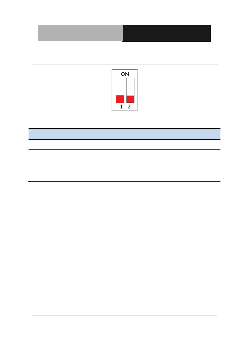
SW1
ATX/AT Mode & Clear CMOS
2.5 List of Switches
The board is fitted with switch(es) that allow you to configure your
system to suit your application.
Chapter 2 Quick Installation Guide 2-20
Page 35
ETX CPU Module
E T X - A 5 5 E
Label
Function
1(OFF)
Normal (Default)
1(ON)
Clear CMOS
2(OFF)
ATX Mode
2(ON)
AT Mode (Default)
2.5.1 ATX/AT Mode & Clear CMOS Switch
ATX Mode (Default)
Chapter 2 Quick Installation Guide 2-21
Page 36

ETX CPU Module E TX- A55E
3
Chapter
AMI
BIOS Setup
Chapter 3 AMI BIOS Setup 3-1
Page 37

ETX CPU Module E TX- A55E
3.1 System Test and Iinitialization
These routines test and initialize board hardware. If the routines
encounter an error during the tests, you will either hear a few short
beeps or see an error message on the screen. There are two kinds
of errors: fatal and non-fatal. The system can usually continue the
boot up sequence with non-fatal errors.
System configuration verification
These routines check the current system configuration stored in the
CMOS memory and BIOS NVRAM. If system configuration is not
found or system configuration data error is detected, system will
load optimized default and re-boot with this default system
configuration autom atic all y.
There are four situations in which you will need to setup system
configuration:
1. You are starting your system for the first time
2. You have changed the hardware attached to your system
3. The system configuration is reset by Clear-CMOS jumper
4. The CMOS memory has lost power and the configuration
information has been erased.
The ETX-A55E CMOS memory has an integral lithium battery
backup for data retention. However, you will need to replace the
complete unit when it finally runs out.
Chapter 3 AMI BIOS Setup 3-2
Page 38

ETX CPU Module E TX- A55E
3.2 AMI BIOS Setup
AMI BIOS ROM has a built-in Setup program that allows users to
modify the basic system configuration. This type of information is
stored in battery-backed CMOS RAM and BIOS NVRAM so that it
retains the Setup information when the power is turned off.
Entering Setup
Power on the computer and press <Del> immediately. This will
allow you to enter Setup.
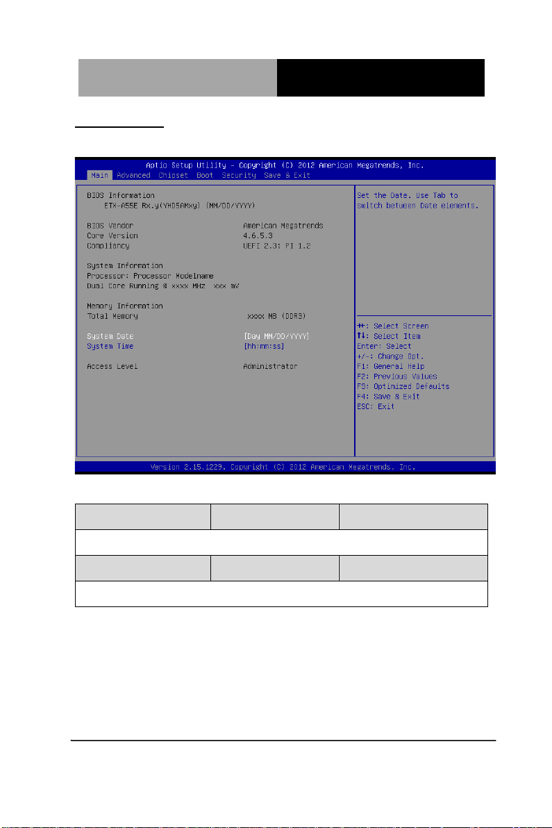
Main
Set the date, use tab to switch between date elements.
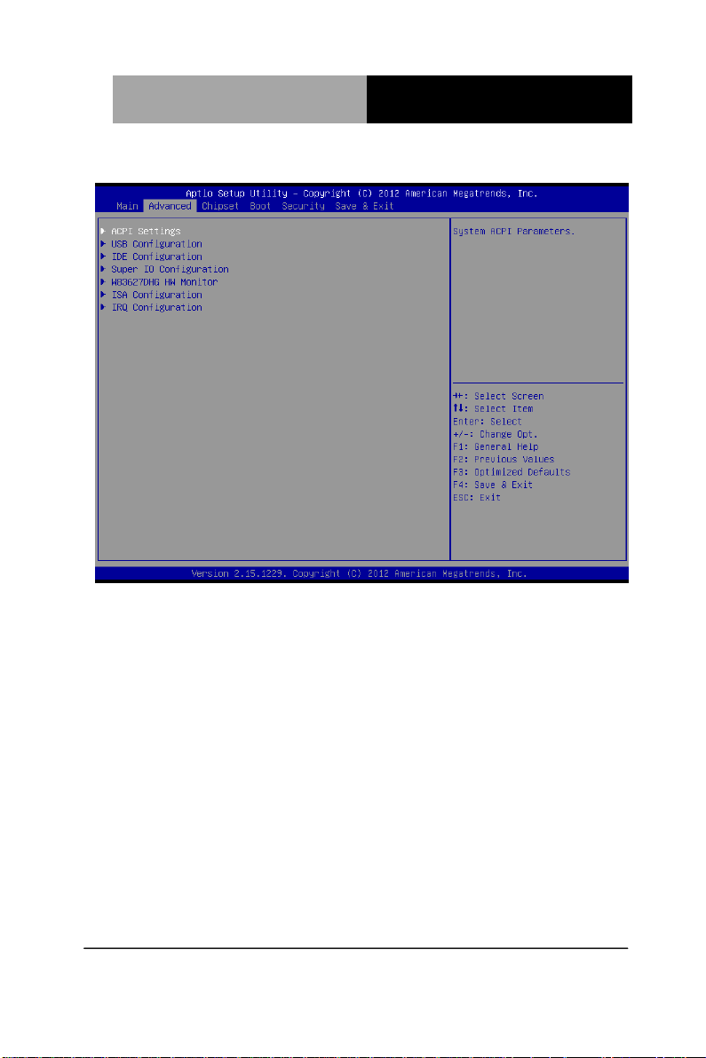
Advanced
Enable disable boot option for legacy network devices.
Chipset
Host bridge parameters.
Boot
Enables/disable quiet boot opt ion.
Security
Set setup administrator password.
Save & Exit
Exit system setup after saving the changes.
Chapter 3 AMI BIOS Setup 3-3
Page 39
ETX CPU Module E TX- A55E
Setup Menu
Setup submenu: Main
Options summary: (default setting)
System Date Day MM:DD:YYYY
Change the month, year and century. The ‘Day’ is changed automatically.
System Time hh : mm : ss
Change the clock of the system.
Chapter 3 AMI BIOS Setup 3-4
Page 40
ETX CPU Module E TX- A55E
Setup submenu: Advanced
Chapter 3 AMI BIOS Setup 3-5
Page 41
ETX CPU Module E TX- A55E
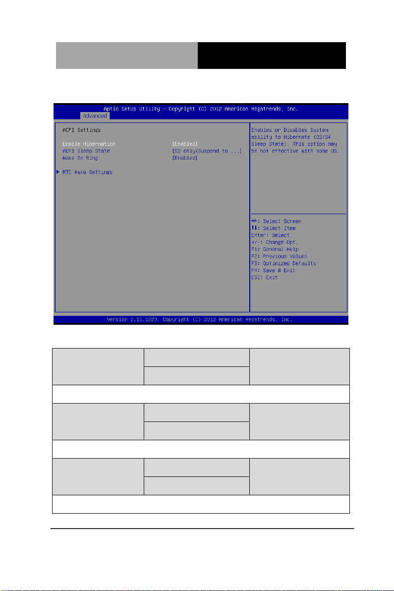
ACPI Settings
Options summary: (default setting)
Enable Hibernation
Enabled or disabled hibernate (OS/S4 Sleep State).
ACPI Sleep State
Select the ACPI state used for System Suspend
Wake on Ring
Enabled or disabled wake on ring function.
Chapter 3 AMI BIOS Setup 3-6
Enabled
Disabled
Suspend Disabled
S3 only(Suspend to RAM)
Enabled
Disabled
Page 42

ETX CPU Module E TX- A55E
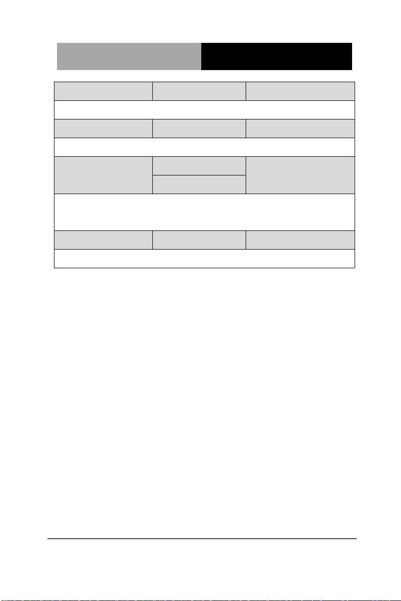
RTC Wake Settings
Enable system to wake from S5 using RTC alarm.
Chapter 3 AMI BIOS Setup 3-7
Page 43
ETX CPU Module E TX- A55E
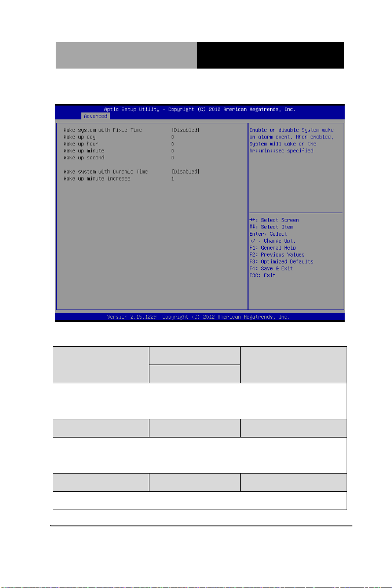
Enable or disable System wake on alarm event. Wake up time is setting by fo llowing
RTC Wake Settings
Options summary: (default setting)
Wake system with Fixed
Time
settings.
Wake up day 0-31
Select 0 for daily system wake up, 1-31 for which day of the month that you would
like the system to wake up
Wake up hour 0-23
Chapter 3 AMI BIOS Setup 3-8
Disabled
Enabled
Page 44
ETX CPU Module E TX- A55E
Wake up minute 0-59
Wake up second 0-59
Wake system with
Dynamic Time
Enable or disable System wake on alarm event. Wake up time is current time +
Increase minutes.
Wake up minute increase 1-5
Disabled
Enabled
Chapter 3 AMI BIOS Setup 3-9
Page 45
ETX CPU Module E TX- A55E
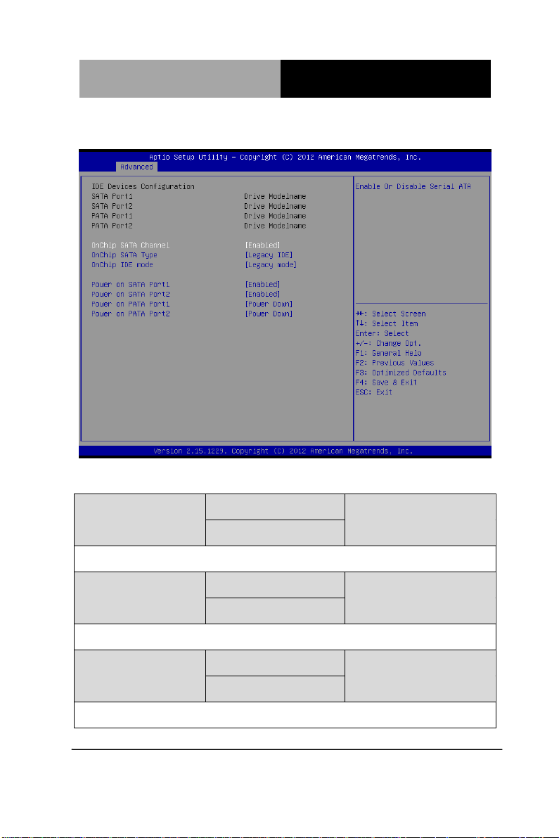
IDE Configuration
Options summary: (default setting)
OnChip SATA Channel Disabled
Enabled
Enable or Disable Serial ATA
OnChip SATA Type Legacy IDE
AHCI
Configure SATA controller operating as IDE/AHCI mode.
OnChip IDE mode Legacy mode
Native mode
Configure IDE controller operating as legacy mode or native PCI device mode.
Chapter 3 AMI BIOS Setup 3-10
Page 46

ETX CPU Module E TX- A55E
SATA Power on SATA
Enabled
Port1/SATA Port2
Enable Or Disable Power on SATA Port1/ SATA Port2.
SATA Power on PATA
Port1/PATA Port2
Enable Or Disable Power on PATA Port1/PATA Port2.
Power Down
Enabled
Power Down
Chapter 3 AMI BIOS Setup 3-11
Page 47
ETX CPU Module E TX- A55E
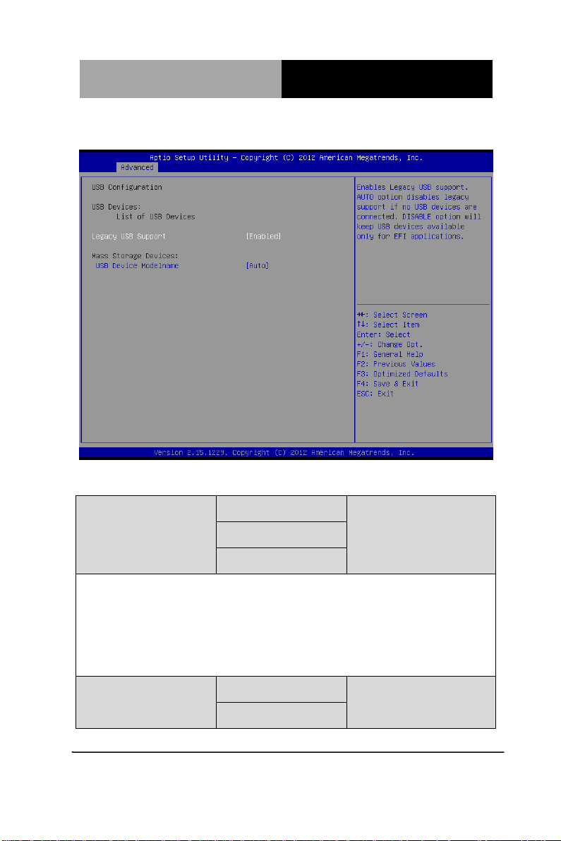
USB Configuration
Options summary: (default setting)
Legacy USB Support Enabled
Disabled
Auto
Enables BIOS Support for Legacy USB Support. When enabled, USB can be
functional in legacy environment like DOS. AUTO option disables legacy support if
no USB devices are connected. DISABLE option will keep USB devices available
only for EFI application
Device Name
(Emulation Type)
Chapter 3 AMI BIOS Setup 3-12
Auto
Floppy
Page 48

ETX CPU Module E TX- A55E
If Auto. USB devices less than 530MB will be emulated as Floppy and remaining as
Forced FDD
Hard Disk
CD-ROM
Floppy and remaining as hard drive. Forced FDD option can be used to force a
HDD formatted drive to boot as FDD(Ex. ZIP drive)
Chapter 3 AMI BIOS Setup 3-13
Page 49
ETX CPU Module E TX- A55E
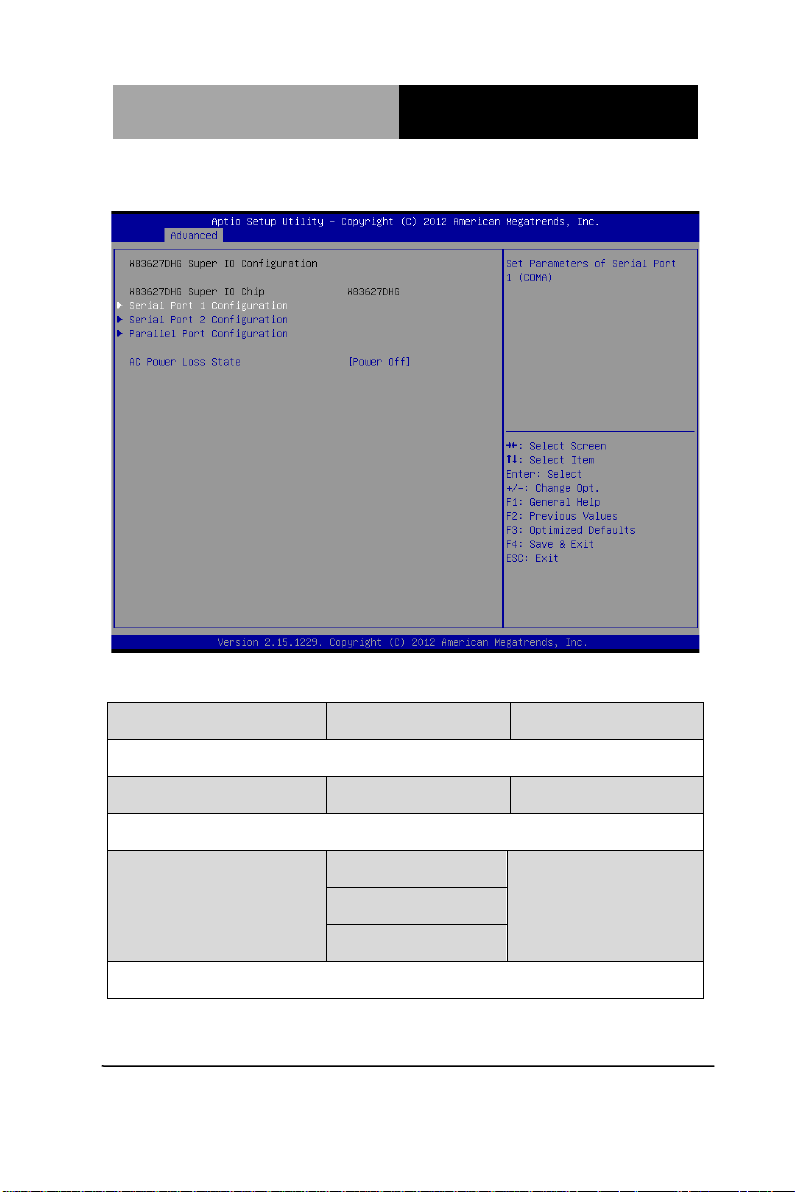
Super IO Configuration
Options summary: (default setting)
Serial Port 1/2 Configuration
Set Parameters of Serial Port 1/2
Parallel Port Configuration
Set Parameters of Parallel Port
AC Power Loss State Power Off
Power On
Last State
Select AC power state when power is re-applied after a power failure.
Chapter 3 AMI BIOS Setup 3-14
Page 50
ETX CPU Module E TX- A55E
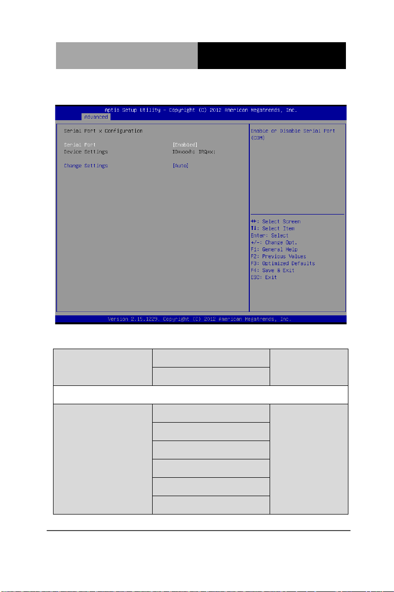
Serial Port 1 Configuration
Options summary: (default setting)
Serial Port Disabled
Enabled
En/Disable specified serial port.
COM1 Change Settings Auto
IO=3F8h; IRQ=4;
IO=3F8h; IRQ=3,4,5,7,10,11,12;
IO=2F8h; IRQ=3,4,5,7,10,11,12;
IO=3E8h; IRQ=3,4,5,7,10,11,12;
IO=2E8h; IRQ=3,4,5,7,10,11,12;
Chapter 3 AMI BIOS Setup 3-15
Page 51
ETX CPU Module E TX- A55E
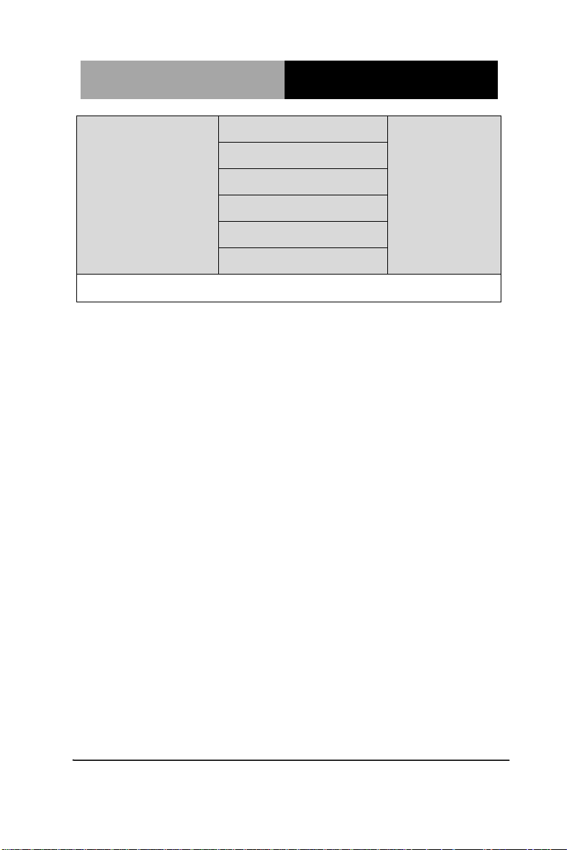
COM2 Change Settings Auto
IO=2F8h; IRQ=3;
IO=3F8h; IRQ=3,4,5,7,10,11,12;
IO=2F8h; IRQ=3,4,5,7,10,11,12;
IO=3E8h; IRQ=3,4,5,7,10,11,12;
IO=2E8h; IRQ=3,4,5,7,10,11,12;
Select a resource setting for Super IO device.
Chapter 3 AMI BIOS Setup 3-16
Page 52
ETX CPU Module E TX- A55E
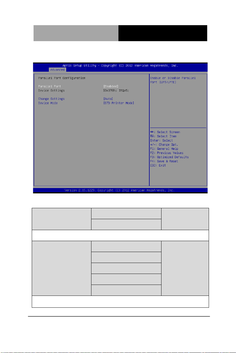
Parallel Port Configuration
Options summary: (default setting)
Parallel Port Disabled
Enabled
En/Disable specified parallel port.
Change Settings
Select an optimal setting for LPT device.
Auto
IO=378h; IRQ=5;
IO=378h; IRQ=5,6,7,10,11,12;
IO=278h; IRQ=5,6,7,10,11,12;
IO=3BCh; IRQ=5,6,7,10,11,12;
Chapter 3 AMI BIOS Setup 3-17
Page 53
ETX CPU Module E TX- A55E
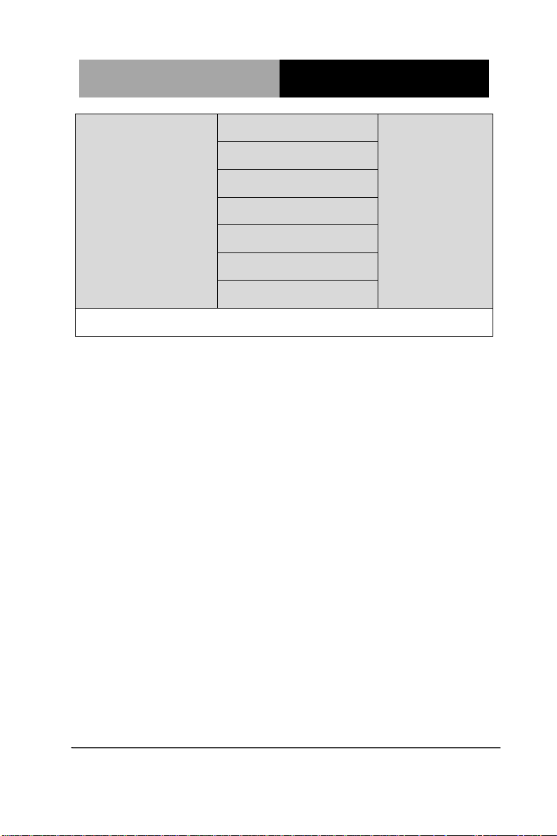
Device Mode STD Printer Mode
SPP Mode
EPP-1.9 and SPP Mode
EPP-1.7 and SPP Mode
ECP Mode
ECP and EPP 1.9 Mode
ECP and EPP 1.7 Mode
Change the Printer Port mode
Chapter 3 AMI BIOS Setup 3-18
Page 54
ETX CPU Module E TX- A55E
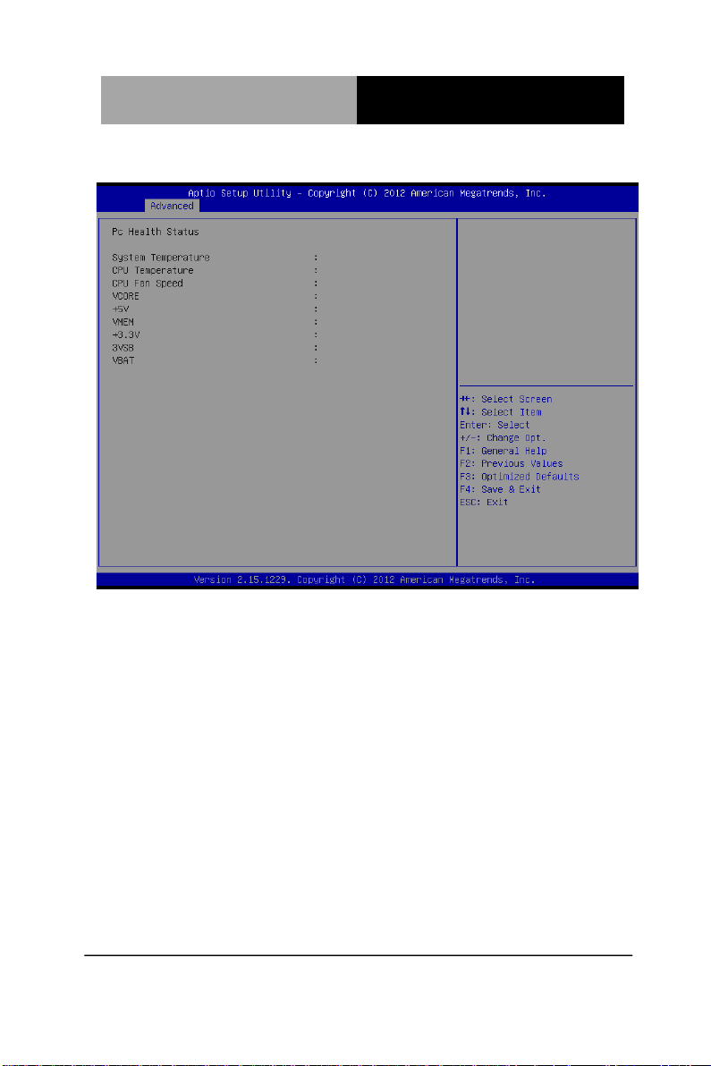
W83627DHG H/W Monitor
Chapter 3 AMI BIOS Setup 3-19
Page 55
ETX CPU Module E TX- A55E
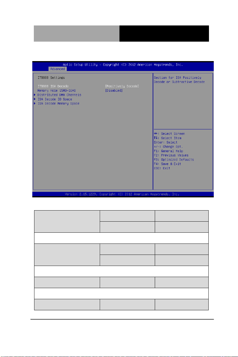
ISA Configuration
Options summary: (default setting)
IT8888 ISA Decode Subtractive Decode
Positively Decode
Selection for ISA Positively Decode or Subtractive Decode
Memory Hole 15MB-16MB Disabled
Enabled
Enable/Disabled 15MB-16MB hole for ISA device
Distributed DMA Channels
IT8888 DDMA channels Configuration setting
ISA Decode IO Space
Chapter 3 AMI BIOS Setup 3-20
Page 56

ETX CPU Module E TX- A55E
IT8888 IO Space Positively Decode Configuration settings
ISA Decode Memory Space
IT8888 Memory Space Positively Decode Configuration settings
Chapter 3 AMI BIOS Setup 3-21
Page 57
ETX CPU Module E TX- A55E
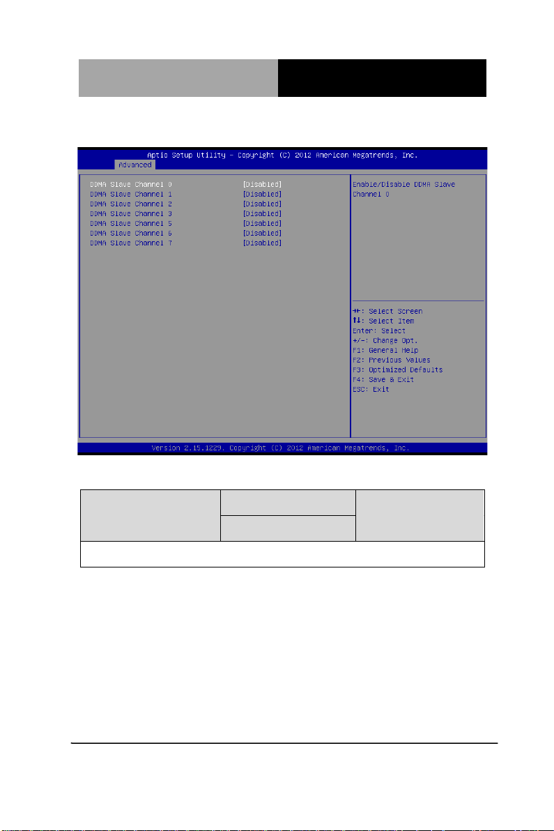
Distributed DMA Channels
Options summary: (default setting)
DDMA Slave Channel 0-7 Disabled
Enabled
Enable/Disable DDMA Slave channel 0-7
Chapter 3 AMI BIOS Setup 3-22
Page 58
ETX CPU Module E TX- A55E
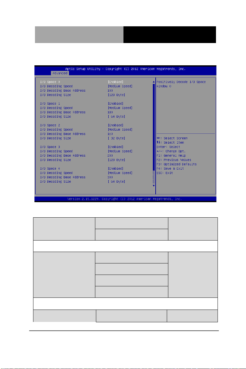
ISA Decode IO Space
Options summary: (default setting)
I/O Space 0 -5 Disabled
Enabled
Enable/Disable Positively IO space decode window
I/O Decoding Speed Subtractive Speed
Slow Speed
Medium Speed
Fast Speed
Select I/O Space decoding speed
I/O Decoding Base Address 0 – FFFF
Chapter 3 AMI BIOS Setup 3-23
Page 59
ETX CPU Module E TX- A55E
I/O Space decoding base address A[15:0]
I/O Decoding Size 1 Byte
2 Byte
4 Byte
8 Byte
16 Byte
32 Byte
64 Byte
128 Byte
Select I/O Space decoding size
I/O Decode Defaults
Space 0 100/128Byte
Space 1 180/64Byte
Space 2 1C0/32Byte
Space 3 200/128Byte
Space 4 300/64Byte
Space 5 340/32Byte
Default setting for I/O decode 0-5
Chapter 3 AMI BIOS Setup 3-24
Page 60
ETX CPU Module E TX- A55E
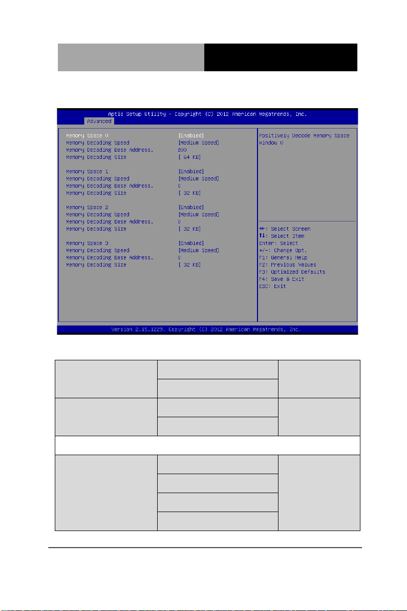
ISA Decode Memory Space
Options summary: (default setting)
Memory Space 0 Disabled
Enabled
Memory Space 1-3 Disabled
Enabled
Enable/Disable Positively memory space decode window
Memory Decoding Speed Subtractive Speed
Slow Speed
Medium Speed
Fast Speed
Chapter 3 AMI BIOS Setup 3-25
Page 61
ETX CPU Module E TX- A55E
Select Memory Space decoding speed
Memory Decoding Base
Address
Memory Space decoding base address A[23:8]
Memory Decoding Size 16 K B
Select Memory Space decoding size
Memory Decode Defaults
Space 0 D00/64KB
Space 1-3 0/32Byte
Default setting for memory decode 0-3
0 – FFFF
32 KB
64 KB
128 KB
256 KB
512 KB
1 MB
2 MB
Chapter 3 AMI BIOS Setup 3-26
Page 62
ETX CPU Module E TX- A55E
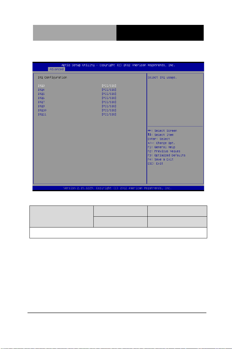
IRQ Configuration
Options summary: (default setting)
IRQ3/IRQ4/IRQ5/IRQ6
IRQ7/IRQ9/IRQ10/IRQ11
Select specified IRQ can be used by PCI device or reserved for ISA devices.
Reserved
PCI/SIO
Chapter 3 AMI BIOS Setup 3-27
Page 63
ETX CPU Module E TX- A55E
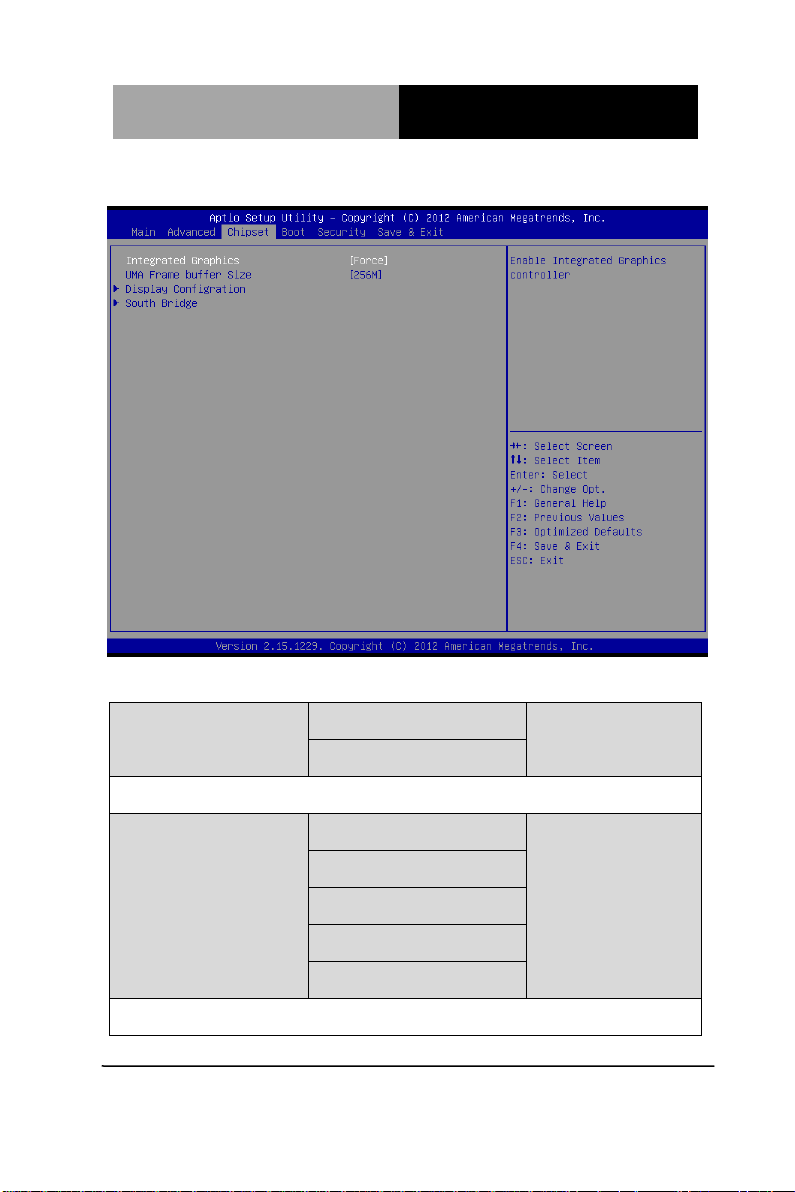
Setup submenu: Chipset
Options summary: (default setting)
Integrated Graphics Auto
Force
Enable Integrated Graphic controller
UMA Frame buffer Size 32M
64M
128M
256M
512M
Set UMA Frame buffer size
Chapter 3 AMI BIOS Setup 3-28
Page 64
ETX CPU Module E TX- A55E
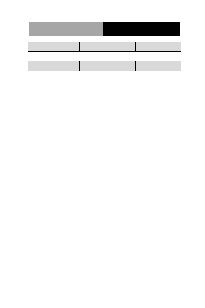
Display Configuration
Specify options for Display interface
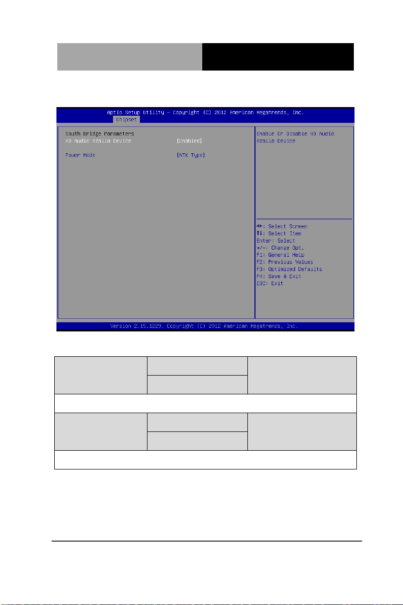
South Bridge
South Bridge Parameters
Chapter 3 AMI BIOS Setup 3-29
Page 65
ETX CPU Module E TX- A55E
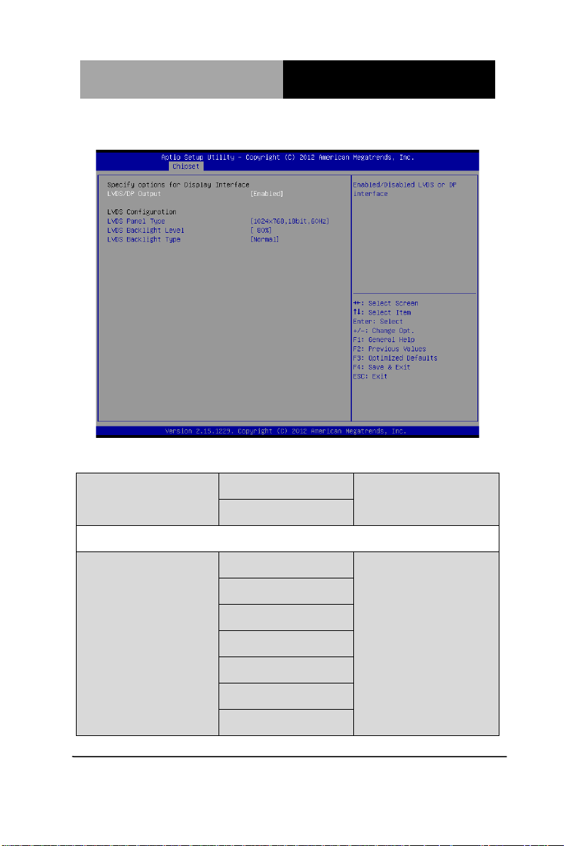
Display Configuration
Options summary: (default setting)
LVDS/DP Output Enabled
Disabled
Enabled/Disabled LVDS
LVDS Panel Type 640x480,18bit,60Hz
800x480,18bit,60Hz
800x600,18bit,60Hz
1024x600,18bit,60Hz
1024x768,18bit,60Hz
1024x768,24bit,60Hz
1280x768,24bit,60Hz
Chapter 3 AMI BIOS Setup 3-30
Page 66
ETX CPU Module E TX- A55E
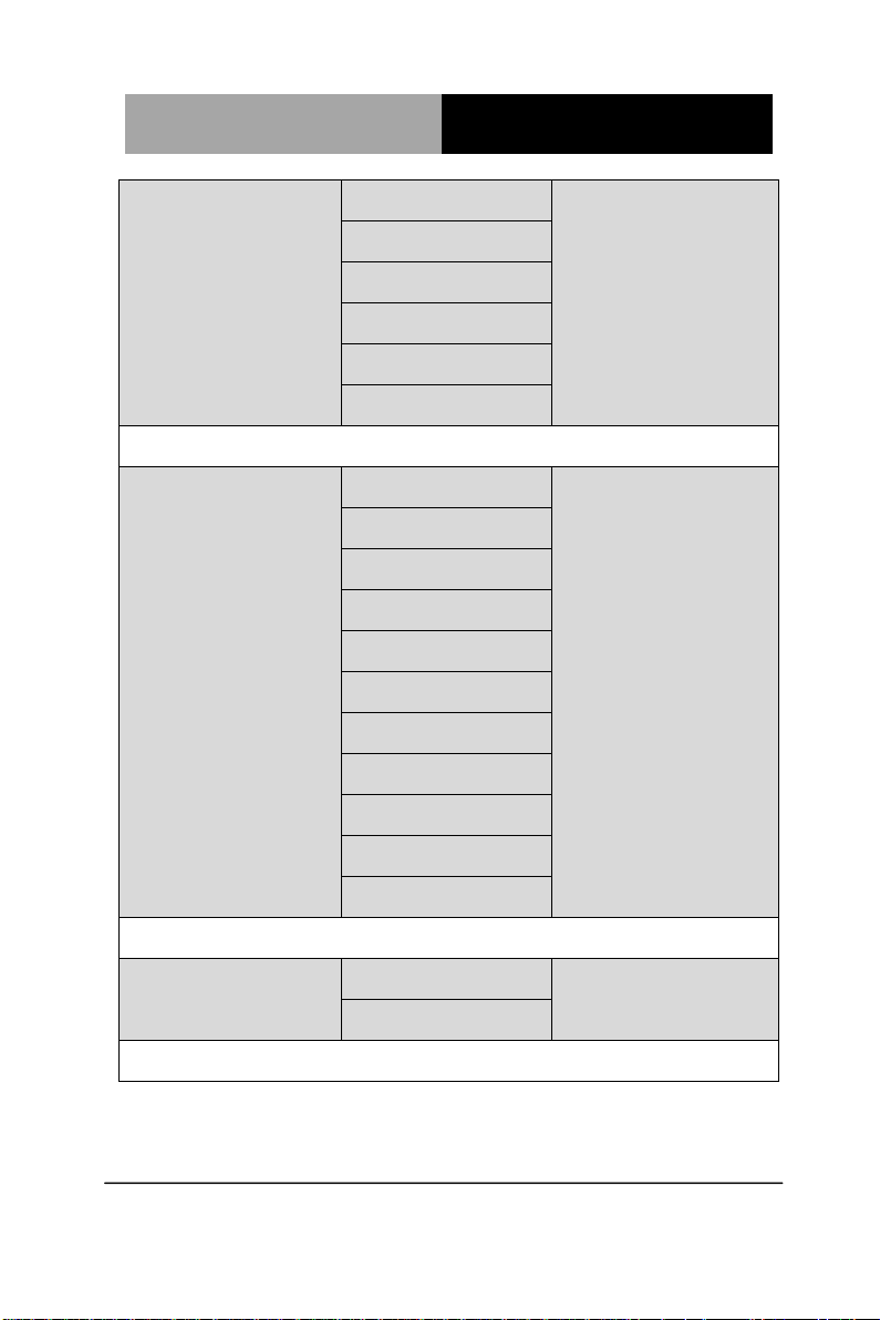
1280x1024,48bit,60Hz
1366x768,24bit,60Hz
1440x900,48bit,60Hz
1600x1200,48bit,60Hz
1920x1080,48bit,60Hz
1920x1200,48bit,60Hz
Select the resolution for LVD S Panel
L VD S Ba c klig ht Level 100%
90%
80%
70%
60%
50%
40%
30%
20%
10%
0%
Select the backlight level for LVDS Panel
LVDS Backlight T y pe Normal
Inverted
Select the signal type for backlight control.
Chapter 3 AMI BIOS Setup 3-31
Page 67
ETX CPU Module E TX- A55E
South Bridge
Options summary: (default setting)
HD Audio Azalia Device Enabled
Disabled
Enable or Disable HD Audio Controller
Power Mode ATX Type
AT Type
Select the power type used on the system
Chapter 3 AMI BIOS Setup 3-32
Page 68
ETX CPU Module E TX- A55E
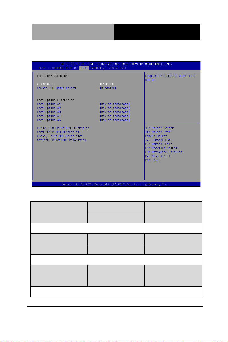
Setup submenu: Boot
Options summary: (default setting)
Quiet Boot Disabled
Enabled
En/Disable showing boot logo.
Launch PXE OpROM
Policy
En/Disable PXE boot for RTL8111E LAN
Boot Option #X/
XXXX Drive BBS Priorities
The order of boot priorities.
Disabled
Enabled
Chapter 3 AMI BIOS Setup 3-33
Page 69
ETX CPU Module E TX- A55E
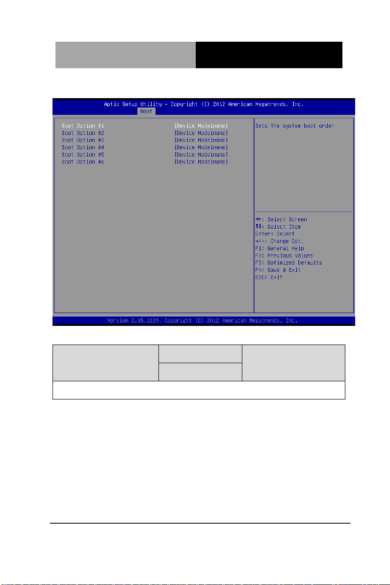
BBS Priorities
Options summary: (default setting)
Boot Option #x Disabled
Device name
Sets the system boot order
Chapter 3 AMI BIOS Setup 3-34
Page 70
ETX CPU Module E TX- A55E
you
A user password does not provide access to many
, a dialog box appears which lets you enter a password. You
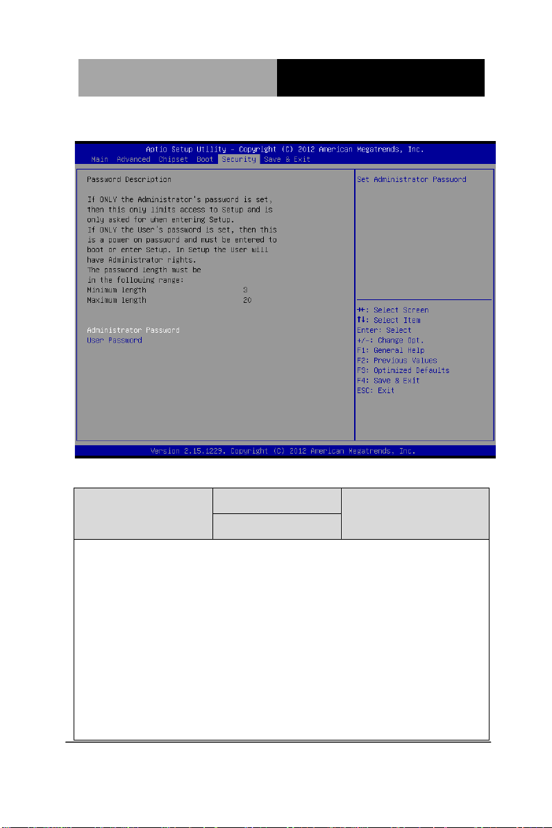
Setup submenu: Security
Options summary: (default setting)
Administrator Password/
User Password
You can install a Supervisor password, and if you install a supervisor password,
can then install a user password.
of the features in the Setup utility.
Install the Password:
Press Enter on this item
can enter no more than six letters or numbers. Press Enter after you have typed in
the password. A second dialog box asks you to retype the password for
confirmation. Press Enter after you have retyped it correctly. The password is
Not set
Chapter 3 AMI BIOS Setup 3-35
Page 71

ETX CPU Module E TX- A55E
required at boot time, or when the user enters the Setup utility.
Removing the Password:
Highlight this item and type in the current password. At the next dialog box press
Enter to disable password protection.
Chapter 3 AMI BIOS Setup 3-36
Page 72
ETX CPU Module E TX- A55E
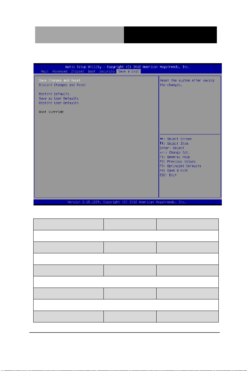
Setup submenu: Exit
Options summary: (default setting)
Save Changes and Reset
Reset the system after saving the changes
Discard Changes and Reset
Reset system setup without saving any changes
Restore Defaults
Restore/Load Default values for all the setup options.
Save as User Defaults
Save the changes done so far as User Defaults
Restore User Defaults
Chapter 3 AMI BIOS Setup 3-37
Page 73

ETX CPU Module E TX- A55E
Restore the User Defaults to all the setup options
Boot Override
Boot to specified device.
Chapter 3 AMI BIOS Setup 3-38
Page 74

ETX CPU Module ETX- A55E
4
Chapter
Driver
Installation
Chapter 4 Driver Installation 4 - 1
Page 75

ETX CPU Module ETX- A55E
The ETX-A55E comes with a driver disk that contains all drivers
and utilities you need to setup your product.
Insert the disk and the installation guide will start automatically. If it
doesn’t, please follow the sequence below to install the drivers.
Follow the sequence below to install the drivers:
Step 1 – Install Chipset/ VGA Drivers
Step 2 – Install LAN Drivers
Step 3 – Install Au dio Drivers
Step 4 – Install AHCI Drivers (Windows XP only, Optional)
Step 5 – Install PCI to ISA Bridge Drivers
Step 6 – Install Serial Port Drivers (Optional)
Please read instructions below for further detailed installations.
Chapter 4 Driver Installation 4 - 2
Page 76

ETX CPU Module ETX- A55E
4.1 Installation
Insert the ETX-A55E driver disk into the disk drive a nd install the
drivers from Step 1 to Step 5 in order.
Step 1 – Install Chipset/ VGA Drivers
Note: For Windows XP users, please install Microsoft.NET
framework 4.5 (included in the step1 folder of the disk) prior to
installing the chipset/ VGA drivers. Users may also go online for the
latest version.
1. Open the STEP 1 - CHIPSET folder and select your OS
2. Open the Setup.exe file in the folder
3. Follow the instructions
4. Drivers will be installed automatically
Step 2 – Install LAN Drivers
1. Open the Step 2 - LAN folder and select your OS
2. Open the Setup.exe file in the folder
3. Follow the instructions
4. Drivers will be installed automatically
Step 3 – Install Audio Driver
1. Click on the Step 3 - AUDIO folder and select your OS
2. Open the Setup.exe file in the folder
Chapter 4 Driver Installation 4 - 3
Page 77

ETX CPU Module ETX- A55E
3. Follow the instructions
4. Drivers will be installed automatically
Step 4 – Install AHCI Driver (Windows XP only, Optional)
Please refer to Appendix D AHCI Settings
Step 5 – Install PCI to ISA Bridge Driver
1. Go to Device Manager
2. Double-click on Other PCI Bridge Device to open the
properties dialog box
3. Select Update Drivers… and Next
4. Select Search for a suitable driver… followed by Next
5. Select Specify a location followed by Next
6. Select Browse
7. Open the Ite file from the disk (Driver/ Step5 – PCI to ISA
Bridge)
8. Follow through the steps to complete installation
Chapter 4 Driver Installation 4 - 4
Page 78
ETX CPU Module ETX- A55E
Step 6 – Install Serial Por t Drivers (Optional)
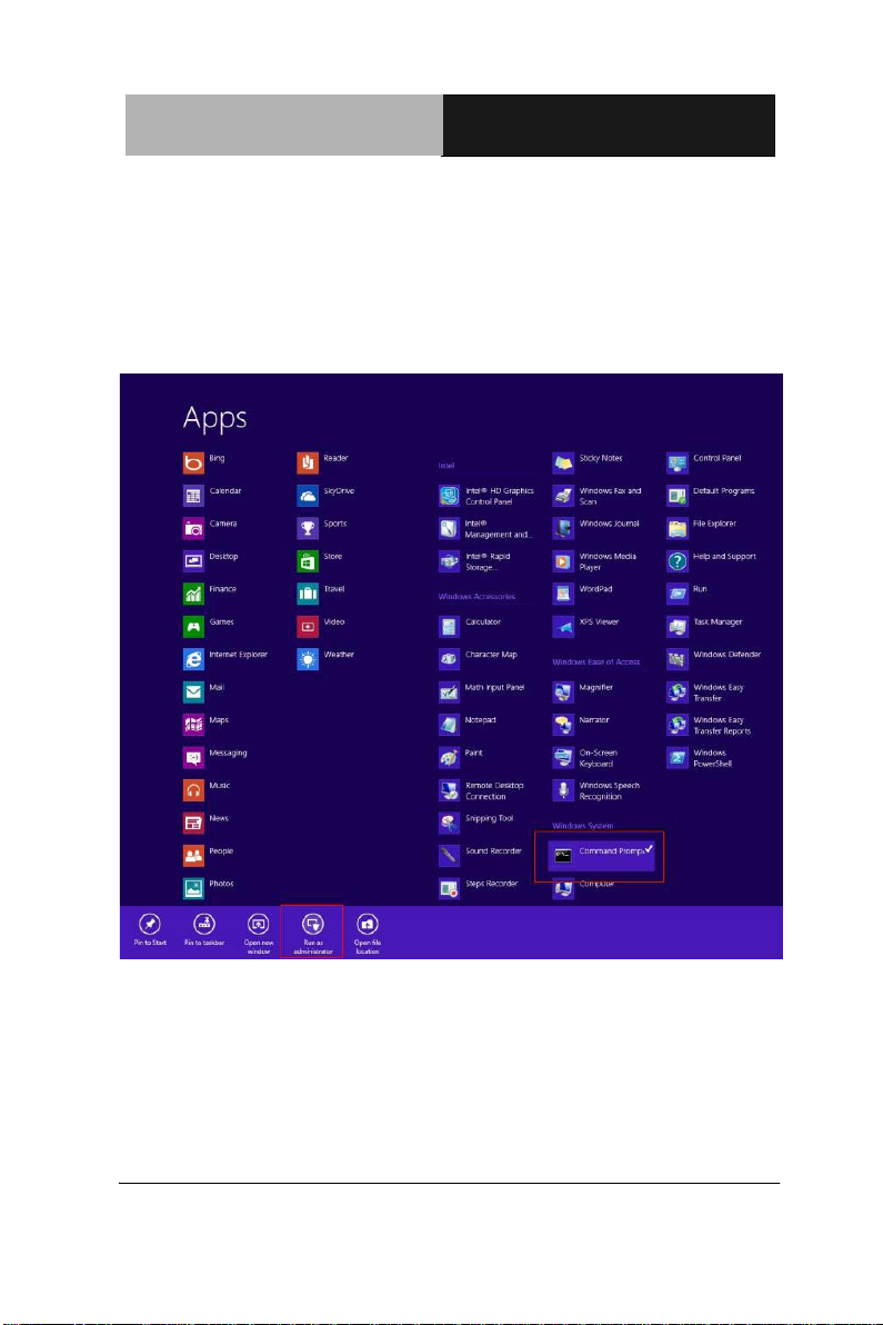
For Windows 8:
1. Open the Apps Screen, right click on the Command
Prompt tile and select Run as Administrator
Chapter 4 Driver Installation 4 - 5
Page 79
ETX CPU Module ETX- A55E
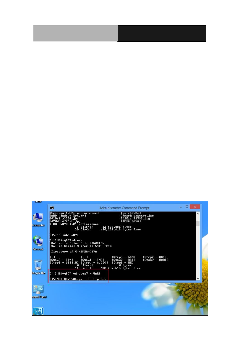
2. To install the driver (patch.bat), you will first have to
locate the file in command prompt. To do that, first go to
the directory which contains the file by entering <drive
letter>: eg. if the driver is in D drive, enter D:
3. You are now at the directory containing the installation
file. Next, go to the folder in which the file resides by
entering cd <folder> eg: if the file is in a folder named
abc, enter cd <abc>.
4. You are now at the folder where the file is located. Enter
the patch.bat to open and install the drivers. If your file
is in a subfolder, enter the cd <folder> command again
to access the subfolder (screenshot below is for
reference only).
Chapter 4 Driver Installation 4 - 6
Page 80
ETX CPU Module ETX- A55E
5. Reboot after installation completes.
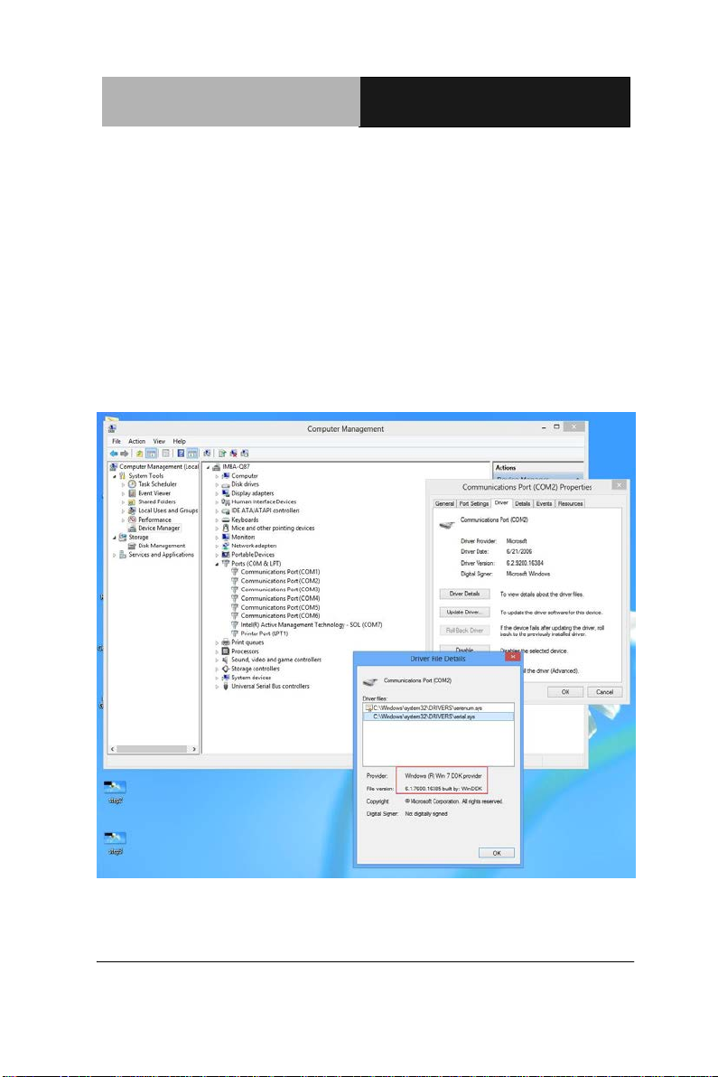
6. To confirm the installation, go to Device Manager,
expand the Ports (COM & LPT) tree and double click on
any of the COM ports to open its properties. Go to the
Driver tab, select Driver Details and click on serial.sys,
you should see its provider as Windows (R) Win 7 DDK
Provider.
Chapter 4 Driver Installation 4 - 7
Page 81
ETX CPU Module ETX- A55E
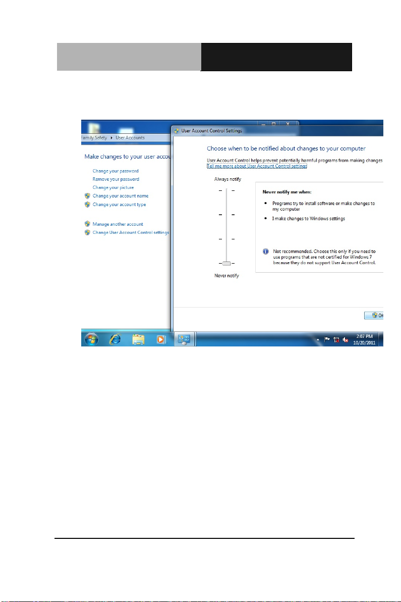
For Windows 7:
1. Change User Account Control settings to Never notify
Chapter 4 Driver Installation 4 - 8
Page 82
ETX CPU Module ETX- A55E
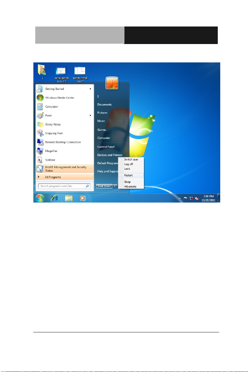
2. Reboot and log in as administrator
Chapter 4 Driver Installation 4 - 9
Page 83
ETX CPU Module ETX- A55E
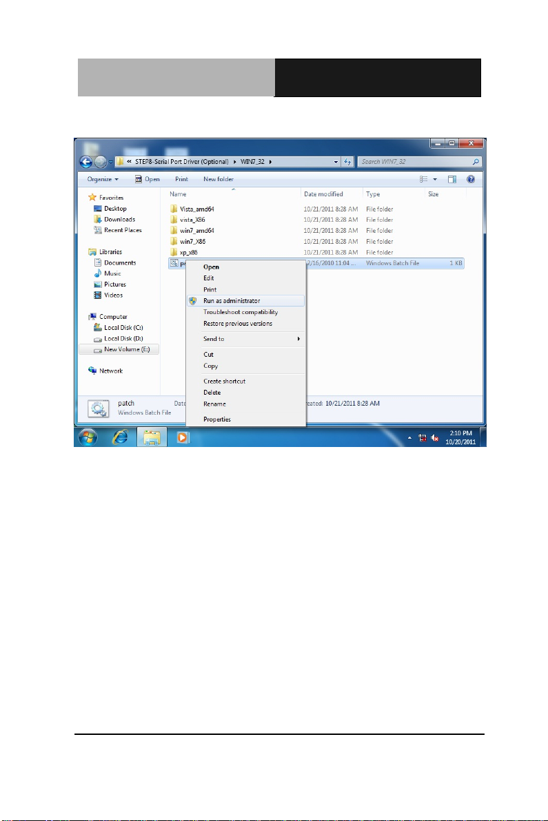
3. Run patch.bat as administrator
For Windows XP
1. Open the Step 6 – Serial Port Driver (Optional) folder
and select your WINXP
2. Open the patch.bat file in the folder
3. Follow the instructions
4. Drivers will be installed automatically
Chapter 4 Driver Installation 4 - 10
Page 84

ETX CPU Module ETX- A55E
A
Appendix
Programming the
W atchdog Timer
Appendix A Programming the Watchdog Timer A-1
Page 85
ETX CPU Module ETX- A55E
A.1 Programming
ETX-A55E utilizes W83627DHG-P chipset as its watchdog timer
controller.
Below are the procedures to complete its configuration and the
AAEON intial watchdog timer program is also attac hed based on
which you can develop customized program to fit your application.
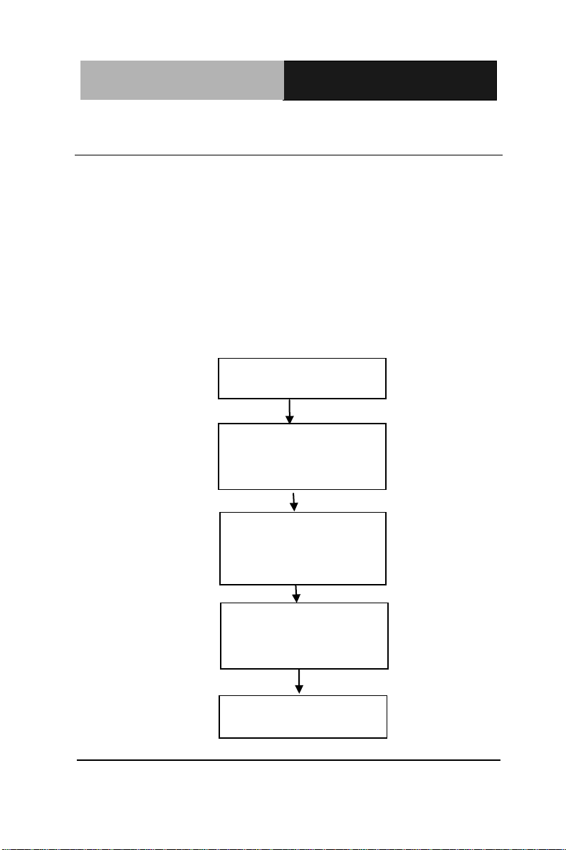
Configuring Sequence Description
Unlock W83627DHG
Select register of
watchdog timer
Enable the function of
the watchdog timer
Use the function of the
watchdog timer
Lock W83627DHG
Appendix A Programming the Watchdog Timer A-2
Page 86

ETX CPU Module ETX- A55E
There are three steps to complete the configuration setup:
(1) Enter the W83627DHG config Mode
(2) Modify the data of configuration registers
(3) Exit the W83627DHG config Mode. Undesired result may
occur if the config Mode is not exited normally.
(1) Enter the W83627DHG config Mode
To enter the W83627DHG config Mode, two special I/O write
operations are to be performed during Wait for Key state. To
ensure the initial state of the key-check logic, it is necessary to
perform two write operations to the Special Address port (2EH).
The differ ent enter keys are provided to s elect configuration ports
(2Eh/2Fh) of the next step.
Address Port Data Port
87h,87h: 2Eh 2Fh
(2) Modify the Data of the Registers
All configuration registers can be accessed after entering the config
Mode. Before accessing a selected register, the content of Index
07h must be changed to the LDN to which the register belongs,
except some Global registers.
Appendix A Programming the Watchdog T imer A-3
Page 87

ETX CPU Module ETX- A55E
(3) Exit the W83627DHG config Mode
The exit key is provided to select configuration ports (2Eh/2Fh) of
the next step.
Address Port Data Port
0aah: 2Eh 2Fh
WatchDog Timer Register I (Index=F5h, Default=00h)
CRF5 (PLED and KBC P20 Control Mode Register)
Bit 7-5 : select PLED mode
= 000 Power LED pin is driven high.
= 001 Power LED pin outputs 0.5Hz pulse
with 50% duty cycle.
= 010 Power LED pin is driven low.
= 011 Power LED pin outputs 2Hz pulse
with 50% duty cycle.
= 100 Power LED pin outputs 1Hz pulse
with 50% duty cycle.
= 101 Power LED pin outputs 4Hz pulse
with 50% duty cycle.
= 110 Power LED pin outputs 0.25Hz pulse
Appendix A Programming the Watchdog Timer A-4
Page 88

ETX CPU Module ETX- A55E
with 50% duty cycle.
=111 Power LED pin outputs 0.25Hz pulse
with 50% duty cycle..
Bit 4 : WDTO# count mode is 1000 times faster.
= 0 Disable.
= 1 Enable.
Bit 3 : select WDTO# count mode.
= 0 second
= 1 minute
Bit 2 : Enable the risin g edge of keyboard Reset
(P20) to force Time-out event.
= 0 Disable
= 1 Enable
Bit 1 : Disable / Enable the WDTO# output low
pulse to the KBRST# pin (PIN60)
= 0 Disable
= 1 Enable
Bit 0 : Reserved.
Appendix A Programming the Watchdog T imer A-5
Page 89

ETX CPU Module ETX- A55E
WatchDog Timer Register II (Index=F6h, Default=00h)
Bit 7-0 = 0 x 00 Time-out Disable
= 0 x 01 Time-out occurs after 1
second/minute
= 0 x 02 Time-out occurs after 2
second/minutes
= 0 x 03 Time-out occurs after 3
second/minutes
………………………………..
= 0 x FF Time-out occurs after 255
second/minutes
WatchDog Timer Register III (Index=F7h, Default=00h)
Bit 7 : Mouse interrupt reset Enable or Disable
= 1 Watchdog Timer is reset upon a
Mouse interrupt
= 0 Watchdog Timer is not affected by
Mouse interrupt
Bit 6 : Keyboard interrupt reset Enable or
Appendix A Programming the Watchdog Timer A-6
Page 90

ETX CPU Module ETX- A55E
Disable
= 1 Watchdog Timer is reset upon a
Keyboard interrupt
= 0 Watchdog Timer is not affected by
Keyboard interrupt
Bit 5 : Force Watchdog Timer Time-out. Write
Only
= 1 Force Watchdog Timer time-out
event: this bit is self-clearing
Bit 4 : Watchdog Timer Status. R/W
= 1 Watchdog Timer time-out occurred
= 0 Watchdog Timer counting
Bit 3-0 : These bits select IRQ resource for
Watchdog. Setting of 2 selects SMI.
Appendix A Programming the Watchdog T imer A-7
Page 91

ETX CPU Module ETX- A55E
A.2 W83627DHG Watchdog Timer Initial Program
Example: Setting 10 sec. as Watchdog timeout interval
;///////////////////////////////////////////////////////////////////////////////////////////////
Mov dx,2eh ;Enter W83627DHG config mode
Mov al,87h (out 87h to 2eh twice)
Out dx,al
Out dx,al
;///////////////////////////////////////////////////////////////////////////////////////////////
Mov al,07h
Out dx,al
Inc dx
Mov al,08h ;Select Logical Device 8 (GPIO Port
2)
Out dx,al
;///////////////////////////////////////////////////////////////////////////////////////////////
Dec dx
Mov al,30h ;CR30 (GP20~GP27)
Out dx,al
Inc dx
Mov al,01h ;Activate GPIO2
Out dx,al
Appendix A Programming the Watchdog Timer A-8
Page 92

ETX CPU Module ETX- A55E
;///////////////////////////////////////////////////////////////////////////////////////////////
Dec dx
Mov al,0f5h ;CRF5 (PLED mode register)
Out dx,al
Inc dx
In al,dx
And al,not 08h ;Set second as counting unit
Out dx,al
;///////////////////////////////////////////////////////////////////////////////////////////////
Dec dx
Mov al,0f6h ; CRF6
Out dx,al
Inc dx
Mov al,10 ;Set timeout interval as 10 sec.
Out dx,al
;///////////////////////////////////////////////////////////////////////////////////////////////
Dec dx ;Exit W83627DHG config mode
Mov al,0aah (out 0aah to 2eh once)
Out dx,al
;///////////////////////////////////////////////////////////////////////////////////////////////
Appendix A Programming the Watchdog T imer A-9
Page 93

ETX CPU Module E TX- A55E
B
Appendix
I/O Information
Appendix B I/O Information B-1
Page 94
ETX CPU Module E TX- A55E
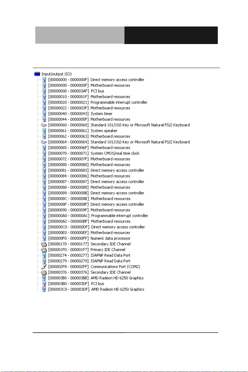
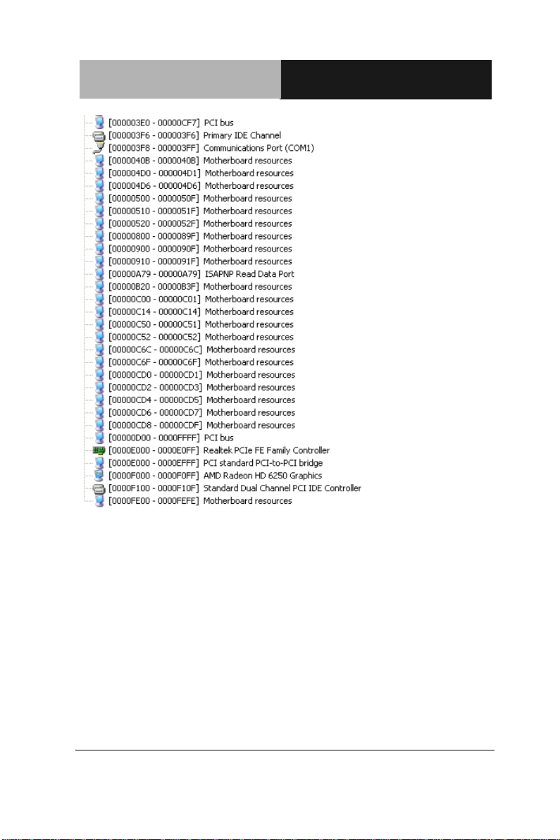
B.1 I/O Address Map
Appendix B I/O Information B-2
Page 95
ETX CPU Module E TX- A55E
Appendix B I/O Information B-3
Page 96
ETX CPU Module E TX- A55E
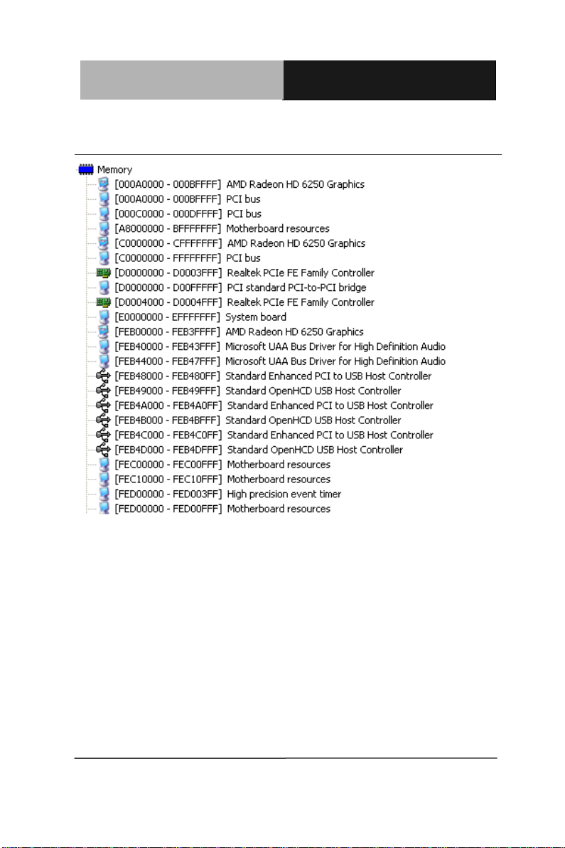
B.2 Memory Address Map
Appendix B I/O Information B-4
Page 97
ETX CPU Module E TX- A55E
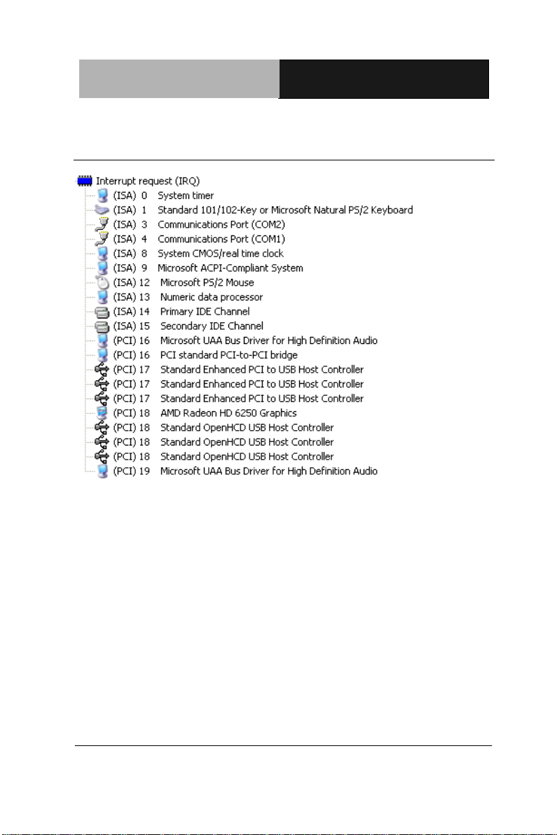
B.3 IRQ Mapping Chart
Appendix B I/O Information B-5
Page 98

ETX CPU Module E TX- A55E
B.4 DMA Channel Assignments
Appendix B I/O Information B-6
Page 99

ETX CPU Module E TX- A55E
C
Appendix
AHCI Settings
Appendix C AHCI Settings C - 1
Page 100
EPIC Board EPIC- B T07
C.1 Setting AHCI
OS installation to SETUP AHCI Mode
Note: Installation is only possible with floppy disks on Windows XP
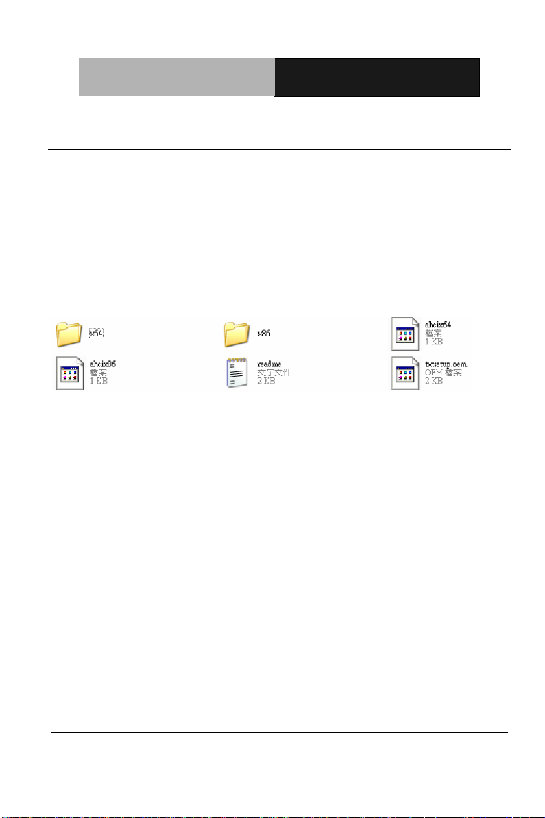
Step 1: Copy files from “Driver DVD -> Step4 – AHCI(Optional)\WinXP_32”
to diskette.
Step 2: Connect the USB Floppy drive to the board and insert the diskette
from previous step.
Step 3: Configure SATA Controller to AHCI mode in BIOS SETUP
Step 4: Boot to DVD/CD-ROM device to install OS
Step 5: Press “F6” to install AHCI driver
Appendix C AHCI Settings C - 2
 Loading...