

Page 1

EMB-KB1
Industrial Motherboard
Page 2

E8620
First Edition
October 2013
Copyright Notice
This document is copyrighted, 2013. All rights are reserved. The original
manufacturer reserves the right to make improvements to the products described
in this manual at any time without notice.
No part of this manual may be reproduced, copied, translated, or transmitted
in any form or by any means without the prior written permission of the original
manufacturer. Information provided in this manual is intended to be accurate and
reliable. However, the original manufacturer assumes no responsibility for its use,
or for any infringements upon the rights of third parties that may result from its use.
The material in this document is for product information only and is subject to
change without notice. While reasonable efforts have been made in the preparation
of this document to assure its accuracy, the original manufacturer assumes no
liabilities resulting from errors or omissions in this document, or from the use of the
information contained herein.
The original manufacturer reserves the right to make changes in the product
design without notice to its users.
Acknowledgments
All other products’ name or trademarks are properties of their respective owners.
AMI is a trademark of American Megatrends Inc.
•
Intel®, Core™ are trademarks of Intel® Corporation.
•
Microsoft Windows® is a registered trademark of Microsoft Corp.
•
IBM, PC/AT, PS/2, and VGA are trademarks of International Business
•
Machines Corporation.
The original manufacturer reserves the right to make changes in the product
design without notice to its users.
All other product names or trademarks are properties of their respective owners.
ii
Page 3

Contents
Chapter 1 Product overview
1.1 Package contents ......................................................................... 1-1
1.2 Features ........................................................................................
1.3 Specications ............................................................................... 1-2
Chapter 2 Motherboard information
2.1 Before you proceed ..................................................................... 2-1
2.2 Motherboard layout ......................................................................
2.3 Screw size .....................................................................................
2.4 AMD Accelerated Processing Unit .............................................
2.5 System memory ...........................................................................
2.6 Jumpers ........................................................................................
2.7 Onboard LEDs ............................................................................
2.8 Connectors .................................................................................
Chapter 3 BIOS setup
3.1 BIOS setup .................................................................................... 3-1
3.2 Main menu ....................................................................................
3.3 Advanced menu ...........................................................................
3.4 Chipset menu ...............................................................................
3.5 Boot menu ....................................................................................
3.6 Security menu ............................................................................
3.7 Save & Exit menu .......................................................................
1-1
2-2
2-4
2-6
2-6
2-8
2-11
2-12
3-2
3-3
3-8
3-9
3-10
3-11
Appendix
Notices .......................................................................................................A-1
iii
Page 4

iv
Page 5
Chapter 1
Product overview
1.1 Package contents
Check your industrial motherboard package for the following items.
1 x Industrial Motherboard
1 x SATA Cable
1 x I/O Shield
1 x Support CD
If any of the above items is damaged or missing, contact your distributor or
sales representative immediately.
1.2 Features
AMD® 1st Generation APU SoC (FT3 BGA package), Quad-core GX-420CA,
•
Dual-core GX-217GA (optional)
Two DDR3 / DDR3L 1600 / 1333 MHz SO-DIMMs up to 16GB
•
SATA 6.0 Gb/s x 2, USB3.0 x 2, USB2.0 x 8
•
PCI-Express x 4, Full-size Mini Card (PCIe + USB + mSATA) + SIM card
•
(mSATA BOM optional) x 1, Half-size Mini Card (PCIe + USB) x 1
VGA, DVI, 18/24-bit Dual Channel LVDS support
•
Chapter 1: General information
1-1
Page 6
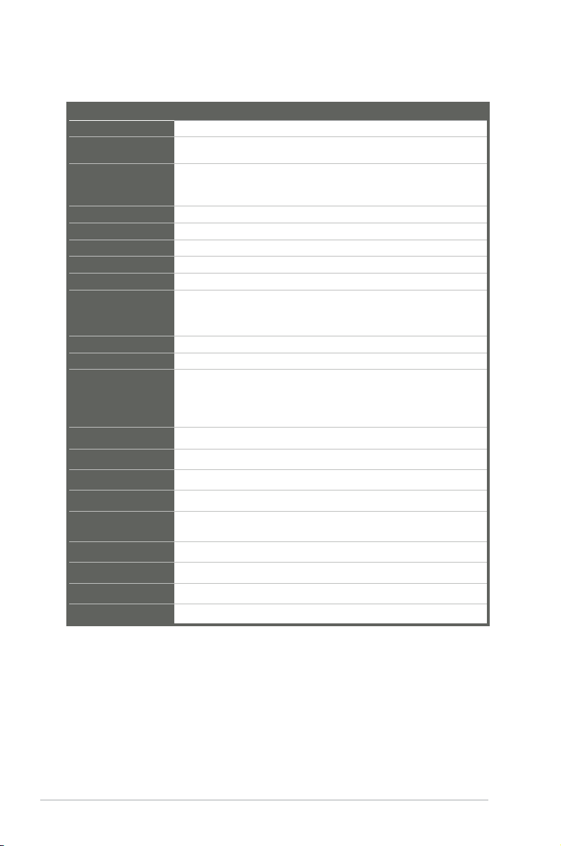
1.3 Specications
Form factor
CPU
Memory
I/O Chipset
Ethernet
BIOS
Wake on LAN
Watchdog Timer
H/W Status Monitor
Smart Fan Control
Power State
Expansion slot
Battery
Power requirement
Board size
Gross weight
Operating
temperature
Storage temperature
Operating humidity
Power compliance
Certicate
Mini-ITX
AMD® 1st generation APU SoC (FT3 BGA package) Quad core GX420CA, Dual-core GX-217GA (optional)
2 x SO-DIMM (8GB per DIMM), max. 16GB, unbuffered, non-ECC
DDR3 / DD3L 1600 / 1333 MHz
Single channel memory architecture
Fintek F81866D-I
2 x Realtek PCIe Gb LAN 8111F
64Mbit Flash AMI BIOS ROM
Yes (WOL/PXE)
1~255 steps by software program
Monitors CPU/Chassis temperature
Monitors Vcore/5V/3.3V/12V voltages
Monitors CPU/Chassis fan speed
CPU Fan/Chassis Fan
S3, S4, S5
4 x PCI Express
1 x Mini Card (PCIe + USB + mSATA) + SIM card (mSATA optional)
Full-size
1 x Mini Card (PCIe + USB) Half size
Lithium battery
1 x ATX connector
6.7 in. x 6.7 in. (17.0 cm x 17.0 cm)
1.1 lb (0.5 Kg)
32oF~140oF (0oC~60oC)
-40oF~185oF (-40oC~85oC)
0%~90% relative humidity, non-condensing
Compliant with Eup/ErP
CE/FCC
SYSTEM
1-2
(continued on the next page)
EMB-KB1
Page 7
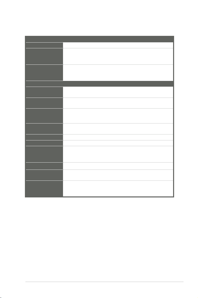
Chipset
Resolution
Output interface
Storage
Serial port
USB
Fan
RTC
Keyboard/Mouse
Audio
Ethernet
Display
Others
DISPLAY
Quad-core GX-420CA / Dual-core GX-217GA (Integrated)
Up to 1920x1200@60Hz for VGA
Up to 1920x1200@60Hz for DVI
Up to 1920x1080@60Hz, Dual Channel 18/24-bit
1 x LVDS
1 x VGA
1 x DVI
I/O
2 x SATA 6.0Gb/s ports
1 x SATA power connector
1 x RS-232/422/485 supports 5V/12V/RI option (COM1 on rear I/O)
5 x RS-232 (COM2 on rear I/O, COM3-COM6 for box header)
2 x USB3.0 (2 ports at rear panel)
8 x USB2.0 (2 ports at rear panel, 4 ports at mid-board, 2 ports at
Mini Card interface)
1 x CPU Fan connector (4-pin)
1 x Chassis Fan connector (4-pin)
Internal RTC
2 x PS/2 Keyboard / mouse port on rear I/O
Mic-in
Line-out
Internal audio for 2W speakers
2 x RJ-45 ports on rear I/O
1 x VGA port on rear I/O
1 x DVI-D port on rear I/O
1 x 8-bit Programmable Digital I/O
1 x Front panel connector
1 x AT/ATX mode select jumper
Chapter 1: General information
1-3
Page 8

1-4
EMB-KB1
Page 9

Chapter 2
Motherboard information
2.1 Before you proceed
Take note of the following precautions before you install motherboard components
or change any motherboard settings.
CAUTION!
• Unplug the power cord from the wall socket before touching any
component.
• Before handling components, use a grounded wrist strap or touch a safely
grounded object or a metal object, such as the power supply case, to avoid
damaging them due to static electricity.
• Hold components by the edges to avoid touching the ICs on them.
• Whenever you uninstall any component, place it on a grounded antistatic
pad or in the bag that came with the component.
• Before you install or remove any component, ensure that the ATX power
supply is switched off or the power cord is detached from the power
supply. Failure to do so may cause severe damage to the motherboard,
peripherals, or components.
Chapter 2: Motherboard information
2-1
Page 10
EATX_PWR2
EATX_PWR1
ALC
887
AAFP1
LVDS1
Super
I/O
MINI_CARD1
MINI_CARD2
CLRTC
J4
17.0cm(6.7in)
17.0cm(6.7in)
DDR3_DIMM_A1 (64bit, 204-pin module)
DDR3_DIMM_A2 (64bit, 204-pin module)
KBMS
AUDIO1
LAN1_USB3_89
LAN2_USB23
F_PANEL
J1
J2
J3
MAIN_PWR_LED1
SB_PWR_LED1
BZ1
USB45
USB67
CHA_FAN
SIM1
CPU_FAN
SATA_PWR1
SATA6G_2
SATA6G_1
COM3
COM4
COM5COM6
DIO1
SPI1
64Mb
BIOS
APU
PCIEX4_1
BATTERY
INV1
CHRONTEL
CH7511B
ASM
1442
RTL
8111F
RTL
8111F
DVI_D1
VGA
COM2
COM1
AMP_CON1
51 2 3
3
10
9
8
6
6
7
18 17 1619 11
12
20
4
13
15
14
21
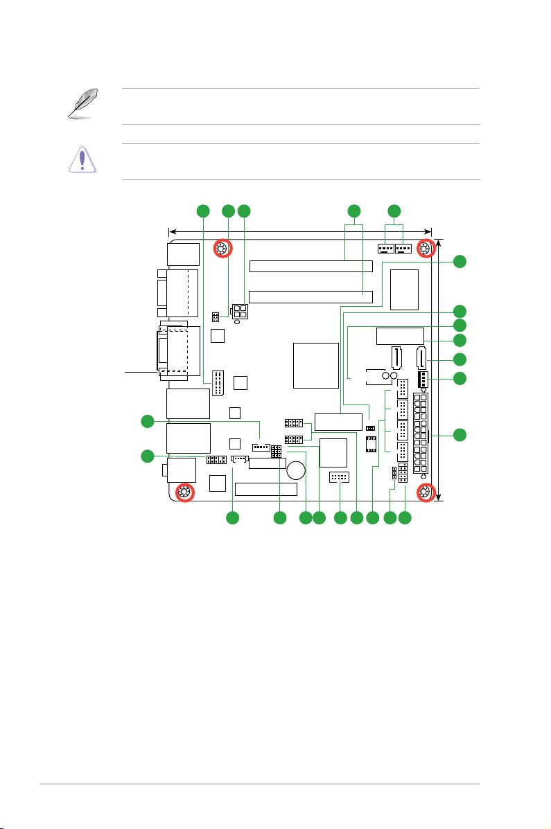
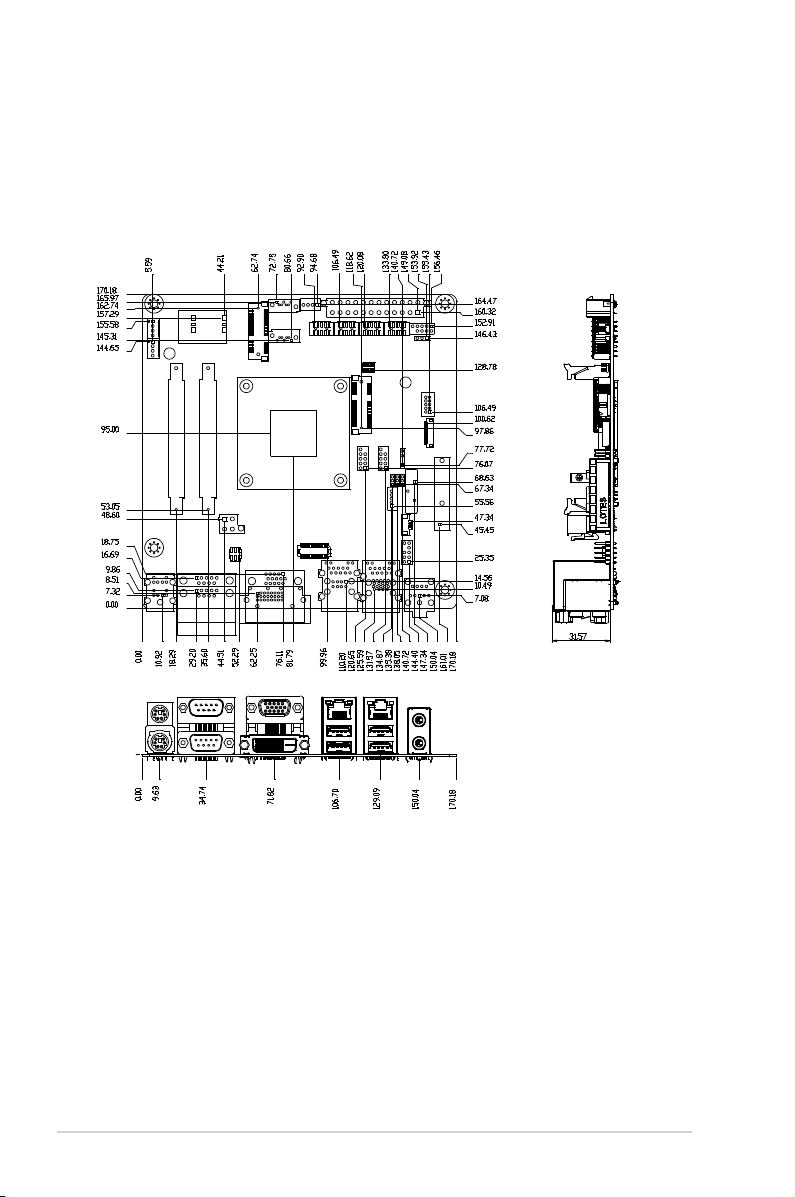
2.2 Motherboard layout
NOTE: Place four screws into the holes indicated by circles to secure the
motherboard to the chassis.
CAUTION! Do not overtighten the screws! Doing so can damage the
motherboard.
Place this side
towards the rear
of the chassis
2-2
EMB-KB1
Page 11

Connectors/Jumpers/Slots
1.
LVDS connector (30-pin LVDS1) 2-19
2.
COM1 Ring/+5V/+12V selection (6-pin J4) 2-10
3.
ATX power connectors (24-pin EATXPWR1, 4-pin EATX_PWR2) 2-14
4.
SO-DIMM memory slots 2-6
5.
CPU and chassis fan connectors (4-pin CPU_FAN, 4-pin CHA_FAN) 2-15
6. Minicard connector (MINI_CARD1, MINI_CARD2) 2-20
7. BIOS programmable connector (8-pin SPI1) 2-21
8. Standby Power LED (Main_PWR_LED1, SB_PWR_LED1) 2-11
9. Serial ATA 6.0Gb/s connectors (7-pin SATA6G_1, SATA6G_2) 2-18
10. SATA power connector (SATA_PWR1) 2-18
11. System panel connector (10-1 pin F_Panel) 2-17
12. Clear RTC RAM (CLRTC) 2-8
13. Serial port connectors (10-1 pin COM3~6) 2-21
14. USB 2.0 connector (10-1 pin USB67, USB45) 2-20
15. Digital I/O connector (DIO1) 2-22
16. LVDS panel voltage selection (3-pin J1) 2-9
17. Inverter voltage selection (3-pin J2) 2-9
18. Inverter backlight control of inverter selector (3-pin J3) 2-10
19. Speaker out connector (AMP_CON1) 2-21
20. Front panel audio connector (10-1 pin AAFP1) 2-16
21. Backlight inverter power connector (5-pin INV1) 2-19
Page
Chapter 2: Motherboard information
2-3
Page 12
2.3 Screw size
2.3.1 Component side
2-4
EMB-KB1
Page 13
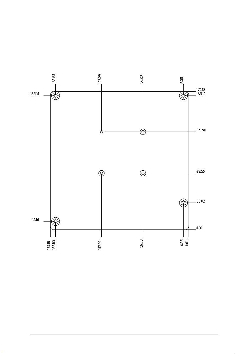
2.3.2 Solder side
Chapter 2: Motherboard information
2-5
Page 14
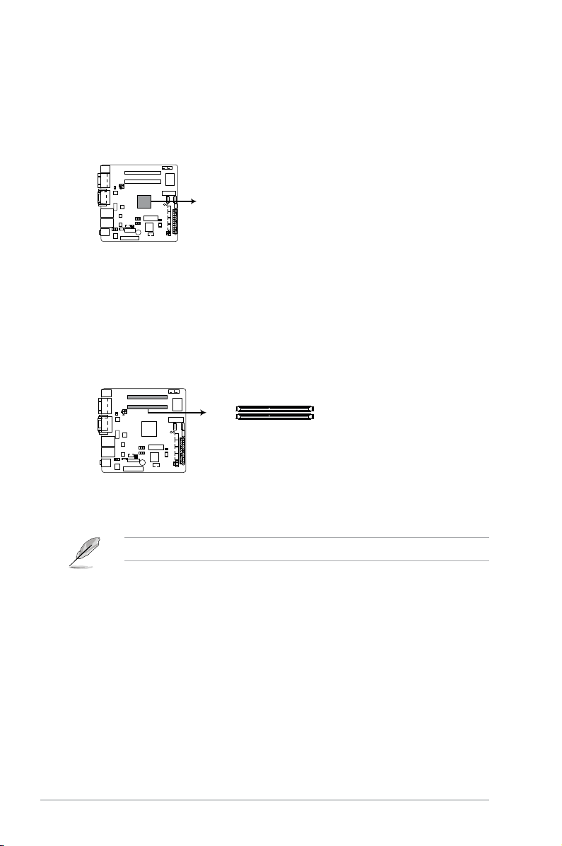
2.4 AMD Accelerated Processing Unit
EMB-KB1 APU
APU
EMB-KB1 204-pin DDR3 / DD3L SO-DIMM sockets
DIMM_A1
DIMM_A2
The motherboard comes with an AMD® 1st Generation APU SoC Quad Core GX420CA, Dual-core GX-217GA (optional).
2.5 System memory
This motherboard comes with two Double Data Rate 3 / Double Data Rate 3 Low
Voltage (DDR3/DD3L) Small Outline Dual Inline Memory Modules (SO-DIMM)
socket. The gure illustrates the location of the DDR3 / DDR3L DIMM socket:
NOTE: Use the SO-DIMM_A2 slot when inserting only one SO-DIMM.
2-6
EMB-KB1
Page 15

2.5.1 Installing a DIMM
1
2
3
To remove a DIMM
B
Chapter 2: Motherboard information
A
2-7
Page 16

2.6 Jumpers
EMB-KB1 Clear RTC RAM
1 2
2 3
Normal
(Default)
Clear RTC1
CLRTC
1. Clear RTC RAM (CLRTC)
This jumper allows you to clear the Real Time Clock (RTC) RAM in CMOS.
You can clear the CMOS memory of system setup parameters by erasing
the CMOS RTC RAM data. The onboard button cell battery powers the RAM
data in CMOS, which include system setup information such as system
passwords.
To erase the RTC RAM:
1. Turn OFF the computer and unplug the power cord.
2. Move the jumper cap from pins 1-2 (default) to pins 2-3. Keep the cap on
pins 2-3 for about 5~10 seconds, then move the cap back to pins 1-2.
3. Plug the power cord and turn ON the computer.
4. Hold down the
to reenter data.
<Del> key during the boot process and enter BIOS setup
CAUTION! Except when clearing the RTC RAM, never remove the cap on
CLRTC jumper default position. Removing the cap will cause system boot
failure!
NOTES:
• If the steps above do not help, remove the onboard battery and move the
jumper again to clear the CMOS RTC RAM data. After clearing the CMOS,
reinstall the battery.
• You do not need to clear the RTC when the system hangs due to
overclocking. For system failure due to overclocking, use the CPU
Parameter Recall (C.P.R) feature. Shut down and reboot the system so the
BIOS can automatically reset parameter settings to default values.
2-8
EMB-KB1
Page 17

EMB-KB1 LVDS Panel Voltage Selection
1 2 2 3
+3V
(Default)
+5V
J1
EMB-KB1 Inverter Voltage Selection
1 2 2 3
+5V
(Default)
+12V
J2
2. LVDS panel voltage selection (3-pin J1)
Setting Pins
+5V 1-2
+3.3V 2-3
3. Inverter voltage selection (3-pin J2)
Setting Pins
+12V 1-2
+5V (Default) 2-3
Chapter 2: Motherboard information
2-9
Page 18

EMB-KB1 COM1 Ring/+5V/+12V Selection
1 2 3 4 5 6
Ring +5V +12V
(Default)
J4
EMB-KB1 Mode Selection for Backlight Control of Inverter
PWM CTLDC CTL
(Default)
1 2 2 3
J3
4. Inverter Backlight Control of Inverter selector (3-pin J3)
Setting Pins
DC Voltage Control 1-2
PWM Control (Default) 2-3
5. COM1 Ring/+5V/+12V selector (COM1)
Setting Pins
+12V (Default) 5-6
+5V 3-4
Ring 1-2
2-10
EMB-KB1
Page 19

SB_PWR_LED1
ON
Standby Power
Powered Off
OFF
ON
Main Power
Main Power Off
OFF
EMB-KB1 Onboard LEDs
MAIN_PWR_LED1
2.7 Onboard LEDs
1. Standby Power LED
The motherboard comes with a standby power LED that lights up to indicate
that the system is ON, in sleep mode, or in soft-off mode. This is a reminder
that you should shut down the system and unplug the power cable before
removing or plugging in any motherboard component. The illustration below
shows the location of the onboard LED.
Chapter 2: Motherboard information
2-11
Page 20

2.8 Connectors
2 3
5
8
4
91011
6
7
1
2.8.1 Rear panel connectors
1. PS/2 Mouse port (green). This port is for a PS/2 mouse.
2. Serial port (COM1). This port connects a modem, or other devices that
conform with serial specication. This serial port also supports RS-232 / RS-
422 / RS-485 connections.
Pin Signal Pin Signal
1 DCD (422TXD-/485DATA-) 2 RXD (422RXD+)
3 TXD (422TXD+/485DATA+) 4 DTR (422RXD-)
5 GND 6 DSR
7 RTS 8 CTS
9 RI/+12V/+5V 10 N.C.
3. Video Graphics Adapter (VGA) port. This 15-pin port is for a VGA monitor
or other VGA-compatible devices.
NOTE: Disable LVDS support when using only the VGA port. Refer to the
section on System Agent (SA) Conguration in Chapter 3 for details.
2-12
EMB-KB1
Page 21

4. LAN1~2 (RJ-45) ports. These ports allow Gigabit connection to a Local Area
Network (LAN) through a network hub. Refer to the table below for the LAN2
port LED indications.
LAN port LED indications
LAN port
Speed
LED
ACT/LINK LED SPEED LED
Status Description Status Description
OFF No link OFF 10 Mbps
connection
ORANGE Linked ORANGE 100 Mbps
connection
BLINKING Data activity GREEN 1 Gbps
connection
Activity Link
LED
5. Line Out port (lime). This port connects to a headphone or a speaker.
6.
Microphone port (pink). This port connects to a microphone.
7. USB 3.0 ports. These two 9-pin Universal Serial Bus (USB) ports connect to
USB 3.0/2.0 devices.
NOTES:
• DO NOT connect a keyboard / mouse to any USB 3.0 port when installing
Windows® operating system.
• Due to USB 3.0 controller limitation, USB 3.0 devices can only be used
under Windows® OS environment and after the USB 3.0 driver installation.
• USB 3.0 devices can be used for data storage only.
• We strongly recommend that you connect USB 3.0 devices to USB 3.0
ports for a faster and better performance from your USB 3.0 devices.
8. USB 2.0 ports. These two 4-pin Universal Serial Bus (USB) ports are
available for connecting USB 2.0/1.1 devices.
9. DVI-D port. This port is for any DVI-D compatible device.
10. Serial port. This port connects a modem, or other devices that conform with
serial specication.
11. PS/2 Keyboard port (purple). This port is for a PS/2 keyboard.
Chapter 2: Motherboard information
2-13
Page 22

2.9.2 Internal connectors
EMB-KB1 ATX power connectors
GND
+5 Volts
+5 Volts
+5 Volts
-5 Volts
GND
GND
GND
PSON#
GND
-12 Volts
+3 Volts
+3 Volts
+12 Volts
+12 Volts
+5V Standby
Power OK
GND
+5 Volts
GND
+5 Volts
GND
+3 Volts
+3 Volts
EATX_PWR1EATX_PWR2
PIN 1
PIN 1
+12V DC
+12V DC
GND
GND
1. ATX power connectors (24-pin EATXPWR1, 4-pin EATXPWR2)
These connectors are for ATX power supply plugs. The power supply plugs
are designed to t these connectors in only one orientation. Find the proper
orientation and push down rmly until the connectors completely t.
IMPORTANT:
• For a fully congured system, we recommend that you use a power supply
unit (PSU) that complies with ATX 12 V Specication 2.0 (or later version).
• DO NOT forget to connect the 4-pin ATX +12V power plug. Otherwise, the
system will not have enough power.
• We recommend that you use a PSU with higher power output when
conguring a system with more power-consuming devices. The system
may become unstable or may not boot up if the power is inadequate.
2-14
EMB-KB1
Page 23

2. CPU and chassis fan connectors (4-pin CPU_FAN, 4-pin CHA_FAN)
EMB-KB1 Fan connectors
CHA_FAN
GND
VCC
SENSE
PWM
CPU_FAN
GND
VCC
SENSE
PWM
Connect the fan cables to the fan connectors on the motherboard, ensuring
that the black wire of each cable matches the ground pin of the connector.
CAUTION: Do not forget to connect the fan cables to the fan connectors.
Insufcient air ow inside the system may damage the motherboard
components. These are not jumpers! Do not place jumper caps on the fan
connectors!
NOTE: The CPU_FAN connector supports a CPU fan of maximum 2A (24 W)
fan power.
Chapter 2: Motherboard information
2-15
Page 24

3. Front panel audio connector (10-1 pin AAFP1)
EMB-KB1 Front panel audio connector
AAFP
AGNDNCSENSE1_RETUR
SENSE2_RETUR
PORT1 L
PORT1 R
PORT2 R
SENSE_SEND
PORT2 L
HD-audio-compliant
pin definition
PIN 1
AGNDNCNC
NC
MIC2
MICPWR
Line out_R
NC
Line out_L
Legacy AC’97
compliant definition
This connector is for a chassis-mounted front panel audio I/O module that
supports either HD Audio or legacy AC`97 audio standard. Connect one end
of the front panel audio I/O module cable to this connector.
IMPORTANT:
• We recommend that you connect a high-denition front panel audio
module to this connector to avail of the motherboard’s high-denition audio
capability.
2-16
EMB-KB1
Page 25

4. System panel connector (10-1 pin F_PANEL)
EMB-KB1 System panel connector
PIN 1
PWR BTN
GND
PWR
PWR_LED-
PWR_LED+
(NC)
HWRST#
Ground
HDD_LEDHDD_LED+
F_PANEL
+PWR LED
+HDD_LED RESET
This connector supports several chassis-mounted functions.
• System power LED (2-pin PWR_LED)
This 2-pin connector is for the system power LED. Connect the chassis
power LED cable to this connector. The system power LED lights up when
you turn on the system power, and blinks when the system is in sleep mode.
•
Hard disk drive activity LED (2-pin HDD_LED)
This 2-pin connector is for the HDD Activity LED. Connect the HDD Activity
LED cable to this connector. The HDD LED lights up or ashes when data is
read from or written to the HDD.
•
ATX power button/soft-off button (2-pin PWR_BTN)
This 2-pin connector is for the system power button.
•
Reset button (2-pin RESET)
This 2-pin connector is for the chassis-mounted reset button for system
reboot without turning off the system power.
Chapter 2: Motherboard information
2-17
Page 26

5. Serial ATA 6.0Gb/s connector (7-pin SATA6G_1, SATA6G_2)
EMB-KB1 SATA 6.0Gb/s connectors
SATA6G_2
SATA6G_1
GND
RSATA_RXP2
RSATA_RXN2
GND
RSATA_TXN2
RSATA_TXP2
GND
GND
RSATA_TXP1
RSATA_TXN1
GND
RSATA_RXN1
RSATA_RXP1
GND
EMB-KB1 SATA POWER Connector
+12V
GND
GND
+5V
SATA_PWR1
ThIS connector connects to Serial ATA 6.0 Gb/s hard disk drives via Serial
ATA 6.0 Gb/s signal cables.
IMPORTANT:
®
• You must install Windows
XP Service Pack 3 or later version before using
Serial ATA hard disk drives.
• When using hot-plug and NCQ, set the SATA Mode Selection item in the
BIOS to [AHCI]. See section 3.3.3IDEConguration for details.
6. SATA power connector (4-pin SATA_PWR1)
This connector is for the SATA power cable. The power cable plug is
designed to t this connector in only one orientation. Find the proper
orientation and push down rmly until the connector completely t.
2-18
EMB-KB1
Page 27

EMB-KB1 LVDS connector
LVDS1
PIN 1
Back Light Control for DC mode
GND
LVDS0_CLK+
GND
LVDS0_D0+
LVDS0_D1+
LVDS0_D2+
LVDS0_D3+
EDID_Clk
LVDS1_D0+
LVDS1_D1+
LVDS1_D2+
LVDS1_D3+
GND
LVDS1_CLK+
LVDS Panel Enable
LVDS VCC
LVDS0_CLKLVDS VCC
LVDS0_D0LVDS0_D1LVDS0_D2LVDS0_D3EDID_Data
LVDS1_D0LVDS1_D1LVDS1_D2LVDS1_D3LVDS VCC
LVDS1_CLK-
7. LVDS connector (30-pin LVDS1)
Inverter VCC
Back Light Control
GND
GND
Back Light Enable
PIN1
EMB-KB1 Inverter Connector
INV1
This connector is for an LCD monitor that supports Low-Voltage Differential
Signaling (LVDS) interface.
8. Backlight inverter power connector (5-pin INV1)
Connect the backlight inverter power cable to this connector.
Chapter 2: Motherboard information
2-19
Page 28

EMB-KB1 USB2.0 connectors
+5V
USB4-
USB4+
GND
(NC)
+5V
USB5-
USB5+
GND
USB45
PIN 1
+5V
USB6-
USB6+
GND
(NC)
+5V
USB7-
USB7+
GND
USB67
PIN 1
EMB-KB1 MINICARD connectors
MINI_CARD1
MINI_CARD2
9. Minicard connector
Use this connector to connect a Minicard reader.
NOTE: The Mini-card module is purchased separately.
10. USB 2.0 connector (10-1 pin USB67 and USB45)
This connector is for USB 2.0 ports. Connect the USB module cable to
connector USB1112. This USB connector complies with USB 2.0 specication
that supports up to 480 Mbps connection speed.
Never connect a 1394 cable to the USB connector. Doing so will damage the
motherboard.
The USB module cable is purchased separately.
2-20
EMB-KB1
Page 29

EMB-KB1 BIOS Programmable Connector
PIN 1
SPI1
GND
SPI_CLK
SPI_MOSI
(NC)
+V3.3SPI
SPI_CS#
SPI_MISO
(NC)
11. BIOS programmable connector (8-pin SPI1)
PIN 1
COM3
DCD
TXD
GND
RTS
RI/+12V/+5V
RXD
DTR
DSR
CTS
PIN 1
COM4
DCD
TXD
GND
RTS
RI/+12V/+5V
RXD
DTR
DSR
CTS
PIN 1
COM5
DCD
TXD
GND
RTS
RI/+12V/+5V
RXD
DTR
DSR
CTS
PIN 1
COM6
DCD
TXD
GND
RTS
RI/+12V/+5V
RXD
DTR
DSR
CTS
EMB-KB1 Serial port connector
Use this connector to ash the BIOS ROM.
12. Serial port connectors (10-1 pin COM3~COM6)
These connectors are for serial (COM) ports. Connect the serial port module
cable to this connector, then install the module to a slot opening at the back
of the system chassis.
NOTE: The COM module is purchased separately.
Chapter 2: Motherboard information
2-21
Page 30

PIN 1
DIO1
DIO_P#1(GPIO80)
DIO_P#3(GPIO82)
DIO_P#5(GPIO84)
DIO_P#7(GPIO86)
+5V
DIO_P#2(GPIO81)
DIO_P#4(GPIO83)
DIO_P#6(GPIO85)
DIO_P#8(GPIO87)
GND
EMB-KB1 DIO connector
EMB-KB1 SPEAKER OUT Connector
PIN 1
LOUTP
LOUTN
ROUTN
ROUTP
AMP_CON1
13. Speaker out connector (4-pin AMP_CON1)
The 4-pin connector is for the chassis-mounted speaker.
NOTE: The Speaker module is purchased separately.
14. Digital I/O connector (10-pin DIO1)
This connector includes 8 I/O lines (In/Out programmable). All of the Digital
I/O lines are programmable and each I/O pin can be individually programmed
to support various devices.
2-22
EMB-KB1
Page 31

Chapter 3
BIOS setup
3.1 BIOS setup
Use the BIOS Setup to update the BIOS or congure settings. The BIOS screens
include navigation keys and help to guide you in using the BIOS Setup program.
Entering BIOS Setup at startup
To enter BIOS Setup at startup:
Press <Delete> during the Power-On Self Test (POST). If you do not press
<Delete>, POST continues with its routine.
Entering BIOS Setup after POST
To enter BIOS Setup after POST:
Press <Ctrl>+<Alt>+<Del> simultaneously.
•
Press the reset button on the system chassis.
•
Press the power button to turn the system off then back on. Do this option only
•
if you failed to enter BIOS Setup using the rst two options.
NOTE: Using the power button, reset button, or the <Ctrl>+<Alt>+<Del> keys
to reboot a running operating system can cause damage to your data or system.
Always shut down the system properly from the operating system.
IMPORTANT:
• The default BIOS settings for this motherboard apply to most working
conditions and ensures optimal performance. If the system becomes
unstable after changing any BIOS settings, load the default settings to
regain system stability. Select the option Restore Defaults under the Save
& Exit Menu. See section 3.7 Exit Menu.
• The BIOS setup screens shown in this section are for reference purposes
only, and may not exactly match what you see on your screen.
Chapter 3: BIOS setup
3-1
Page 32

3.1.1 Menu bar
The menu bar on top of the screen has the following main items:
Main For changing the basic system conguration.
Advanced For changing the advanced system settings.
Chipset For viewing and changing chipset settings.
Boot For changing the system boot conguration.
Security For setting up BIOS security settings.
Save & Exit For selecting the exit options and loading default settings.
To select an item on the menu bar, press the right or left arrow key on the keyboard
until the desired item is highlighted.
3.2 Main menu
The Main menu provides you an overview of the basic system information, and
allows you to set the system date, time, language, and security settings.
3.2.1 System Date [Day MM/DD/YYYY]
Allows you to set the system date.
3.2.2 System Time [HH:MM:SS]
Allows you to set the system time.
3-2
EMB-KB1
Page 33

3.3 Advanced menu
The Advanced menu items allow you to change the settings for the CPU and other
system devices.
Be cautious when changing the settings of the Advanced menu items. Incorrect
eld values can cause the system to malfunction.
3.3.1 ACPI Settings
ACPI Sleep State [S3 only(Suspend to RAM)]
Select ACPI sleep state the system will enter when the Suspend button is pressed.
3.3.2 CPUConguration
The CPU Conguration page displays information about the installed CPU.
3.3.3 IDEConguration
While entering Setup, the BIOS automatically detects the presence of SATA
devices. The SATA Port items show Not Present if no SATA device is installed to
the corresponding SATA port.
OnChip SATA Type [Legacy IDE]
Allows you to set the SATA conguration.
[AHCI] Set to [AHCI] when you want the SATA hard disk drives
to use AHCI (Advanced Host Controller Interface).
AHCI allows the onboard storage driver to enable
advanced Serial ATA features that increases storage
performance on random workloads by allowing the
drive to internally optimize the order of commands.
[Legacy IDE] Set to [IDE] when you want to use the Serial ATA hard
disk drives as Parallel ATA physical storage devices.
Chapter 3: BIOS setup
3-3
Page 34

3.3.4 USBConguration
The USB Devices item lists auto-detected values. If no USB device is detected,
the item shows None.
Legacy USB Support [Enabled]
[Enabled] Enables the support for USB devices on legacy
operating systems (OS).
[Disabled] USB devices are only available when running BIOS
Setup.
[Auto] Allows the system to detect the presence of USB
devices at startup. If detected, the USB controller
legacy mode is enabled. If no USB device is detected,
the legacy USB support is disabled.
3.3.5 F81866SuperIOConguration
SerialPort1~6Conguration
The sub-items in this menu allow you to set the serial port conguration.
Serial Port [Enabled]
Allows you to enable or disable the serial port (COM).
Conguration options: [Enabled] [Disabled]
Change Settings [Auto]
Allows you to select the Serial Port base address.
Conguration options:
[Auto] [IO=3F8h; IRQ=4] [IO=2F8h; IRQ=3]
RS Mode [RS232]
Allows you to select COM RS Mode.
Conguration options: [RS232] [RS422] [RS485]
3-4
EMB-KB1
Page 35

3.3.6 F81866 H/W Monitor
The items in this menu allow you to congure hardware monitoring settings.
Smart Fan Function [Enabled]
Allows you to enable or disable Smart Fan Function. Conguration options:
[Enabled] [Disabled]
SmartFanModeConguration
Fan 1~2 Smart Fan Control [Auto Duty-Cycle Mode]
Select Smart Fan mode. Conguration options: [Auto Duty Cycle Mode]
[Manual RPM Mode] [Manual Duty Mode] [Auto RPM Mode]
Temperature 1~4
Input temperature value to congure fan control. Input value range: [1~100]
Duty Cycle 1~4
Input duty cycle to congure fan control. Input value range: [1~100]
The following item replaces Duty Cycle when Smart Fan Control is set to Auto
RPM Mode.
RPM Percentage 1~4
Input RPM percentage to congure fan control. Input value range: [1~100]
Manual Duty Mode [60]
Input duty cycle value for PWM fan. Input value range: [1~100]
Manual Duty Mode is the only available item when Smart Fan Control is set to
Manual Duty Mode.
Manual RPM Mode [2000]
Input RPM count value for PWM fan. Input value range: [500~10000]
Manual RPM Mode is the only available item when Smart Fan Control is set to
Manual RPM Mode.
Chapter 3: BIOS setup
3-5
Page 36

3.3.7 Dynamic Digital IO
The items in this menu allow you to modify Digital IO settings.
GPIO1~3 Direction [Input]
Set GPIO data ow as Input or Output. Conguration options: [Input] [Output]
GPO0~3 Direction [Output]
Set GPO0 data ow as Input or Output. Conguration options: [Input] [Output]
Output Level [Hi]
Conguration options: [Hi][Low]
3.3.8 Power Management
Power Mode [ATX Type]
Select power supply mode. Conguration options: [ATX Type] [AT Type]
Power Failure [Last State]
Select AC power loss/failure response. Conguration options: [Last State] [Always
On] [Always Off]
ERP Function [Enabled]
This item disables/enables ERP mode for energy star compliance.
Conguration options: [Disabled] [Enabled]
Resume from RI [Enabled]
This item disables/enables Resume from RI.
Conguration options: [Disabled] [Enabled]
3-6
EMB-KB1
Page 37

3.3.9 S5 RTC Wake Settings
Wake System with Fixed Time [Disabled]
Enable or disable system wake on at an alarm event. When enabled, the system
will wake up at the specied hr::min::sec. Conguration options: [Disabled]
[Enabled]
The following items appear when Wake System with Fixed Time is enabled.
Wake up day/hour/minute/second [0]
Specify the values for day/hour/minute/second.
Wake System with Dynamic Time [Disabled]
Enable or disable system wake on at an alarm event. When enabled, the system
will wake up at the current time plus a specied number of minutes.
The following items appear when Wake System with Dynamic Time is
enabled.
Wake up minute increase [1]
Specify the number of minutes added to the current time before waking up
system.
Chapter 3: BIOS setup
3-7
Page 38

3.4 Chipset menu
The Chipset menu items allow you to change conguration options for the North
Bridge and South Bridge.
3.4.1 North Bridge
DDR3L Voltage Selection [1.5V]
Conguration options: [1.35V] [1.5V]
PCI GEN Speed [GEN2]
Conguration options: [GEN1] [GEN2]
GFXConguration
DP0 Output Mode [LVDS]
Conguration options: [LVDS] [Disabled]
LVDS1 [Enabled]
Conguration options: [Disabled] [Enabled]
LVDS1 Panel Type [1024x768, 18bit, 60Hz]
Select the type of LCD panel used as display.Conguration options:
[640x480, 18bit, 60Hz] [800x480, 18bit, 60Hz] [800x600, 18bit, 60Hz]
[1024x600, 18bit, 60Hz] [1024x768, 18bit, 60Hz] [1024x768, 24bit, 60Hz]
[1280x768, 24bit, 60Hz] [1280x1024, 48bit, 60Hz] [1366x768, 24bit, 60Hz]
[1440x900, 48bit, 60Hz] [1600x1200, 48bit, 60Hz] [1920x1080, 48bit, 60Hz]
[1920x1200, 48bit, 60Hz]
LVDS Backlight Level [80%]
Select the default backlight brightness of the LVDS display. Conguration
options: [100%] [90%] [80%] ~ [0%]
LVDS Backlight Type [Normal]
Select backlight control type. Conguration options: [Normal] [Inverted]
DP1 Output Mode [Single Link DVI-D]
Conguration options: [Single Link DVI-D] [Disabled]
3.4.2 South Bridge
HD Audio Azalia Device [Enabled]
Conguration options: [Enabled] [Disabled]
3-8
EMB-KB1
Page 39

3.5 Boot menu
The Boot menu items allow you to change the system boot options.
3.5.1 BootConguration
Quiet Boot [Enabled]
This item enables/disables Quiet Boot.
Conguration options: [Disabled] [Enabled]
Launch PXE OpROM [Disabled]
This item enables/disables Legacy PXE OpROM.
Conguration options: [Disabled] [Enabled]
3.5.2 Boot Option Priorities
These items specify the boot device priority sequence from the available devices.
The number of device items that appears on the screen depends on the number of
devices installed in the system.
• To select the boot device during system startup, press <F7> during POST.
• To access Windows OS in Safe Mode, do any of the following:
- Press <F5> during POST.
- Press <F8> after POST.
Chapter 3: BIOS setup
3-9
Page 40

3.6 Security menu
The Security menu items allow you to change the system security settings.
3.6.1 Administrator Password
If you have set an administrator password, we recommend that you enter the
administrator password for accessing the system. Otherwise, you might be able to
see or change only selected elds in the BIOS setup program.
To set an administrator password:
1. Select the
2. From the
<Enter>.
3. Conrm the password when prompted.
To change an administrator password:
1. Select the
2. From the
press <Enter>.
3. From the
<Enter>.
4. Conrm the password when prompted.
To clear the administrator password, follow the same steps as in changing an
administrator password, but press <Enter> when prompted to create/conrm the
password. After you clear the password, the Administrator Password item on top
of the screen shows Not Installed.
Administrator Password item and press <Enter>.
Create New Password box, key in a password, then press
Administrator Password item and press <Enter>.
Enter Current Password box, key in the current password, then
Create New Password box, key in a new password, then press
3.6.2 User Password
If you have set a user password, you must enter the user password for accessing
the system. The User Password item on top of the screen shows the default Not
Installed. After you set a password, this item shows Installed.
To set a user password:
1. Select the
2. From the
<Enter>.
3. Conrm the password when prompted.
3-10
User Password item and press <Enter>.
Create New Password box, key in a password, then press
EMB-KB1
Page 41

To change a user password:
1. Select the
2. From the
press <Enter>.
3. From the
<Enter>.
4. Conrm the password when prompted.
To clear the user password, follow the same steps as in changing a user password,
but press <Enter> when prompted to create/conrm the password. After you clear
the password, the User Password item on top of the screen shows Not Installed.
User Password item and press <Enter>.
Enter Current Password box, key in the current password, then
Create New Password box, key in a new password, then press
3.7 Save & Exit menu
Save Changes & Reset
Once you are nished making your selections, choose this option from the Exit
menu to ensure the values you selected are saved. When you select this option, a
conrmation window appears. Select Yes to save changes and exit.
Discard Changes & Reset
This option allows you to exit the Setup program without saving your changes.
When you select this option or if you press <Esc>, a conrmation window appears.
Select Yes to discard changes and exit.
Restore Defaults
This option allows you to restore/load default values for all setup options.
Save as User Defaults
This item saves current conguration as User Default.
Restore User Defaults
This option restores User Defaults to all setup options.
Boot Override
These items displays the available devices. The number of device items that
appears on the screen depends on the number of devices installed in the system.
Click an item to start booting from the selected device.
Chapter 3: BIOS setup
3-11
Page 42

3-12
EMB-KB1
Page 43

Appendix
Notices
Federal Communications Commission Statement
This device complies with Part 15 of the FCC Rules. Operation is subject to the
following two conditions:
This device may not cause harmful interference.
•
This device must accept any interference received including interference that
•
may cause undesired operation.
This equipment has been tested and found to comply with the limits for a
Class A digital device, pursuant to Part 15 of the FCC Rules. These limits are
designed to provide reasonable protection against harmful interference in a
residential installation. This equipment generates, uses and can radiate radio
frequency energy and, if not installed and used in accordance with manufacturer’s
instructions, may cause harmful interference to radio communications. However,
there is no guarantee that interference will not occur in a particular installation. If
this equipment does cause harmful interference to radio or television reception,
which can be determined by turning the equipment off and on, the user is
encouraged to try to correct the interference by one or more of the following
measures:
Reorient or relocate the receiving antenna.
•
Increase the separation between the equipment and receiver.
•
Connect the equipment to an outlet on a circuit different from that to which the
•
receiver is connected.
Consult the dealer or an experienced radio/TV technician for help.
•
EMB-KB1
WARNING! The use of shielded cables for connection of the monitor to the
graphics card is required to assure compliance with FCC regulations. Changes
or modications to this unit not expressly approved by the party responsible for
compliance could void the user’s authority to operate this equipment.
DO NOT throw the motherboard in municipal waste. This product has been designed to
enable proper reuse of parts and recycling. This symbol of the crossed out wheeled bin
indicates that the product (electrical and electronic equipment) should not be placed in
municipal waste. Check local regulations for disposal of electronic products.
DO NOT throw the mercury-containing button cell battery in municipal waste. This symbol
of the crossed out wheeled bin indicates that the battery should not be placed in municipal
waste.
A-1
Page 44

電子信息產品污染控制標示:圖中之數字為產品之環保使用期限。僅指電子
信息產品中含有的有毒有害物質或元素不致發生外洩或突變從而對環境造成
污染或對人身、財產造成嚴重損害的期限。
有毒有害物 質 或 元 素 的 名稱及 含 量 說 明 標 示 :
有害物質或元素
部件名稱
印刷電路板 及其
電子組件
外部信號連 接頭
及線材
鉛 (Pb) 汞 (Hg)
× ○ ○ ○ ○ ○
× ○ ○ ○ ○ ○
鎘 (Cd)
六 價 鉻
(Cr(VI))
多 溴 聯 苯
(PBB)
多 溴二 苯醚
(PBDE)
○: 表示該有毒有害物質在該部件所有均質材料中的含量均在 SJ/T 11363-
2006 標准規定的限量要求以下。
×: 表示該有毒有害物質至少在該部件的某一均質材料中的含量超出 SJ/T
11363-2006 標准規定的限量要求,然該部件仍符合歐盟指令 2002/95/
EC 的規范。
備註:此產品所標示之環保使用期限,係指在一般正常使用狀況下。
A-2
EMB-KB1
 Loading...