

Page 1

Industrial Motherboard
EMB-CV1 series
EMB-CV1 series
Manual 2nd Ed.
June 2013
Page 2

Industrial Motherboard
EMB-CV1 series
Copyright Notice
This document is copyrighted, 2013. All rights are reserved. The
original manufacturer reserves the right to make improvements to
the products described in this manual at any time without notice.
No part of this manual may be reproduced, copied, translated, or
transmitted in any form or by any means without the prior written
permission of the original manufacturer. Information provided in this
manual is intended to be accurate and reliable. However, the
original manufacturer assumes no responsibility for its use, or for
any infringements upon the rights of third parties that may result
from its use.
The material in this document is for product information only and is
subject to change without notice. While reasonable efforts have
been made in the preparation of this document to assure its
accuracy, the original manufacturer assumes no liabilities resulting
from errors or omissions in this document, or from the use of the
information contained herein.
The original manufacturer reserves the right to make changes in the
product design without notice to its users.
i
Page 3

Industrial Motherboard
EMB-CV1 series
Acknowledgments
All other products’ name or trademarks are properties of their
respective owners.
AMI is a trademark of American Megatrends Inc.
CompactFlash™ is a trademark of the Compact Flash
Association.
Intel® and Atom™ are trademarks of Intel® Corporation.
Microsoft Windows® is a registered trademark of Microsoft
Corporation.
ITE is a trademark of Integrated Technology Express, Inc.
IBM, PC/AT, PS/2, and VGA are trademarks of International
Business Machines Corporation.
SoundBlaster is a trademark of Creative Labs, Inc.
Please be notified that all other products’ name or trademarks
not be mentioned above are properties of their respective
owners.
ii
Page 4

Industrial Motherboard
EMB-CV1 series
Packing List
(Standard, not bulk pack)
Before you begin installing your card, please make sure that
the following materials have been shipped:
1 Cable Set (SATA Cable, SATA Power Cable)
1 Metal I/O Bracket
1 Product CD
1 Industrial Motherboard
If any of these items should be missing or damaged, please
contact your distributor or sales representative immediately.
iii
Page 5

Industrial Motherboard
EMB-CV1 series
Contents
Chapter 1 General Information
1.1 Features .................................................................... 1-2
1.2 Specifications ............................................................ 1-3
Chapter 2 Quick Installation Guide
2.1 Safety Precautions .................................................. 2-2
2.2 Location of Connectors and Jumpers ...................... 2-3
2.3 Mechanical Drawing ................................................ 2-4
2.4 List of Jumpers ........................................................ 2-6
2.5 List of Connectors ..................................................... 2-7
2.6 Setting Jumpers ....................................................... 2-9
2.7 AT/ATX Mode Selection (ATMODE) ..................... 2-10
2.8 Clear COMS (CLRTC)............................................. 2-10
2.9 COM2 External Power Selection (DIGITALREFENCE)
....................................................................................... 2-10
2.10 LVDS Panel Power Selection (LVDS_VDD_SEL) 2-10
2.11 LVDS Brightness Control Type Selection
(L_BRIGHTNESS) ......................................................... 2-10
2.12 LVDS function Enable (LVDS_SWITCH) .............. 2-11
2.13 LVDS Panel Backlight Power Selection
(LCD_POWER_SEL) .................................................... 2-11
2.14 Watchdog Timer Function Switch (WDT) .............. 2-11
iv
Page 6

Industrial Motherboard
EMB-CV1 series
2.15 +12V AUX Power Connector (CON2) ................... 2-11
2.16 CPU/SYSTEM FAN Connector (CPU_FAN/CHA_FAN)
....................................................................................... 2-11
2.17 COM3/COM4/COM5 RS232 Serial Port PIN HEADER
(COM3/COM4/COM5) ................................................... 2-12
2.18 GPIO/SM BUS/COM2/ COM2 External Power
Selection (DIGITALREFENCE) ..................................... 2-12
2.19 COM2 RS-232/422/485 connector ........................ 2-13
2.20 Front Panel Pin Header (F_PANEL) ..................... 2-13
2.21 PS/2 Keyboard/Mouse Connector (KB/MS) .......... 2-13
2.22 LVDS Panel Power Connector (LCD_POWER) ... 2-14
2.23 Parallel Port Connector (LPT) ............................... 2-14
2.24 LVDS Panel Connector (LVDS) ............................ 2-15
2.25 Serial ATA power Connector (SATA_PWR1) ....... 2-16
2.26 USB 5 & 6 PIN HEADER (USB56) ........................ 2-16
2.27 USB 7 PIN HEADER (USB7) .............................. 2-17
Chapter 3 AMI BIOS Setup
3.1 System Test and Initialization. .................................. 3-2
3.2 AMI BIOS Setup ........................................................ 3-3
Chapter 4 Driver Installation
4.1 Installation………………………………………..……..4-3
v
Page 7

Industrial Motherboard
EMB-CV1 series
Appendix A Programming The Watchdog Timer
A.1 Programming ........................................................... .A-2
A.2 ITE8783 Watchdog Timer Initial Program .………....A-6
Appendix B Mating Connector
B.1 List of Mating Connectors and Cables ..................... .B-2
vi
Page 8

Industrial Motherboard
EMB-CV1 series
Chapter
1
General
Information
Chapter 1 General Information 1- 1
Page 9

Industrial Motherboard
EMB-CV1 series
1.1 Features
Onboard Intel® Atom™ D2550 Processor
Intel® NM10
Intel® Graphics Media Accelerator 3600 Supports DirectX
10, OpenGL 3.0
DDR3 800/1066 SO-DIMM x 2, Max. 4GB
VGA, 18/24-bit LVDS, DVI, Dual Independent Display
Dual Gigabit Ethernet
COM x 5 (RS-232 x 4, RS-232/422/485 x 1)
USB2.0 x 6, SATA 3Gb/s x 2
PCI-Express [x1] x 1, Full-size Mini Card + SIM slot x 1
(m-SATA option, if use m-SATA, one of SATA port and
Mini Card + SIM Card will be disable)
5.1 CH Audio Channel
Chapter 1 General Information 1-2
Page 10

Industrial Motherboard
EMB-CV1 series
1-3
Processor
Intel® Atom™ D2550 Dual Core
Processor, up to 1.86GHz
System Memory
204-pin single channel DDR3
800/1066 DIMM x 2, Max. 4GB
(When you install only one
memory module, install it on
DIMM A2 slot)
Chipset
Intel
®
NM10
I/O Chipset
ITE IT8783F
Ethernet
Realtek 8111E for
10/100/1000Base-TX, RJ-45 x 2
BIOS
AMI BIOS, 32MB ROM
Wake On LAN
Yes
Watchdog Timer
System reset: 1~255 steps
programmable
H/W Status Monitoring
Supports Power Supply Voltage,
Fan Speed, and Temperature
Monitoring
Expansion Interface
PCI-Express[x1] x 1,
Full-size Mini Card + SIM Card
slot x 1 (m-SATA option)
Battery
Lithium battery
Power Requirement
DC 12V
(selectable AT/ATX mode)
Board Size
6.7”(L) x 6.7”(W)
(170 mm x 170 mm)
Gross Weight
1.1 lb (0.5 Kg)
1.2 Specifications
System
Chapter 1 General Information
Page 11

Industrial Motherboard
EMB-CV1 series
Operating Temperature
32˚F~ 140˚F (0˚C ~ 60˚C)
Storage Temperature
-40˚F~ 185˚F (-40˚C ~ 85˚C)
Operating Humidity
5%~95% relative humidity,
non-condensing
Chipset
Intel® Graphics Media Accelerator
3650
Resolution
Up to 1440x900 18/24-bit
LCD Interface
18/24-bit LVDS
Video Interface
VGA x 1, DVI-D x 1
Storage
SATA x 2 (support AHCI mode)
(if use m-SATA, one SATA port
will be disable)
Serial Port
RS-232 x 4, RS-232/422/485 x 1
(RS-422/485 is selectable by
BIOS)
Parallel Port
STD/SPP/EPP
USB
USB2.0 x 6
(5x2 pin header for internal x 2,
onboard Type A connector x 4)
Digital I/O
Supports 8-bit (Programmable)
PS/2 Port
Keyboard/ Mouse x 1
Audio
Line-in, Mic-in, Line-out
Display
I/O
Chapter 1 General Information 1-4
Page 12

Industrial Motherboard
EMB-CV1 series
Chapter
2
Quick
Installation
Guide
Chapter 2 Quick Installation Guide 2 - 1
Page 13
Industrial Motherboard
EMB-CV1 series
Always completely disconnect the power cord
from your board whenever you are working on
it. Do not make connections while the power is
on, because a sudden rush of power can
damage sensitive electronic components.
Always ground yourself to remove any static
charge before touching the board. Modern
electronic devices are very sensitive to static
electric charges. Use a grounding wrist strap at
all times. Place all electronic components on a
static-dissipative surface or in a static-shielded
bag when they are not in the chassis
2.1 Safety Precautions
Chapter 2 Quick Installation Guide 2 - 2
Page 14
Industrial Motherboard
EMB-CV1 series
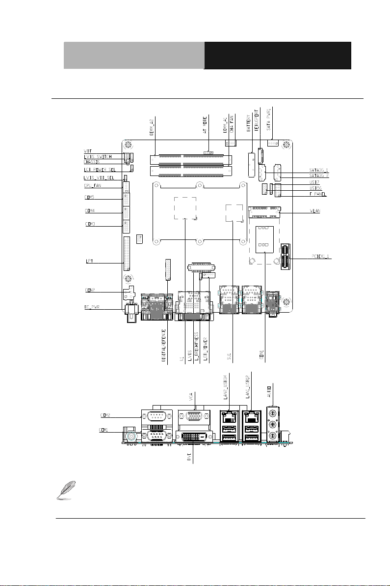
2.2 Location of Connectors and Jumpers
NOTE: If choose m-SATA SKU, SATA3G_2 port, mini card and SIM
card slot will be disable.
Chapter 2 Quick Installation Guide 2 - 3
Page 15
Industrial Motherboard
EMB-CV1 series
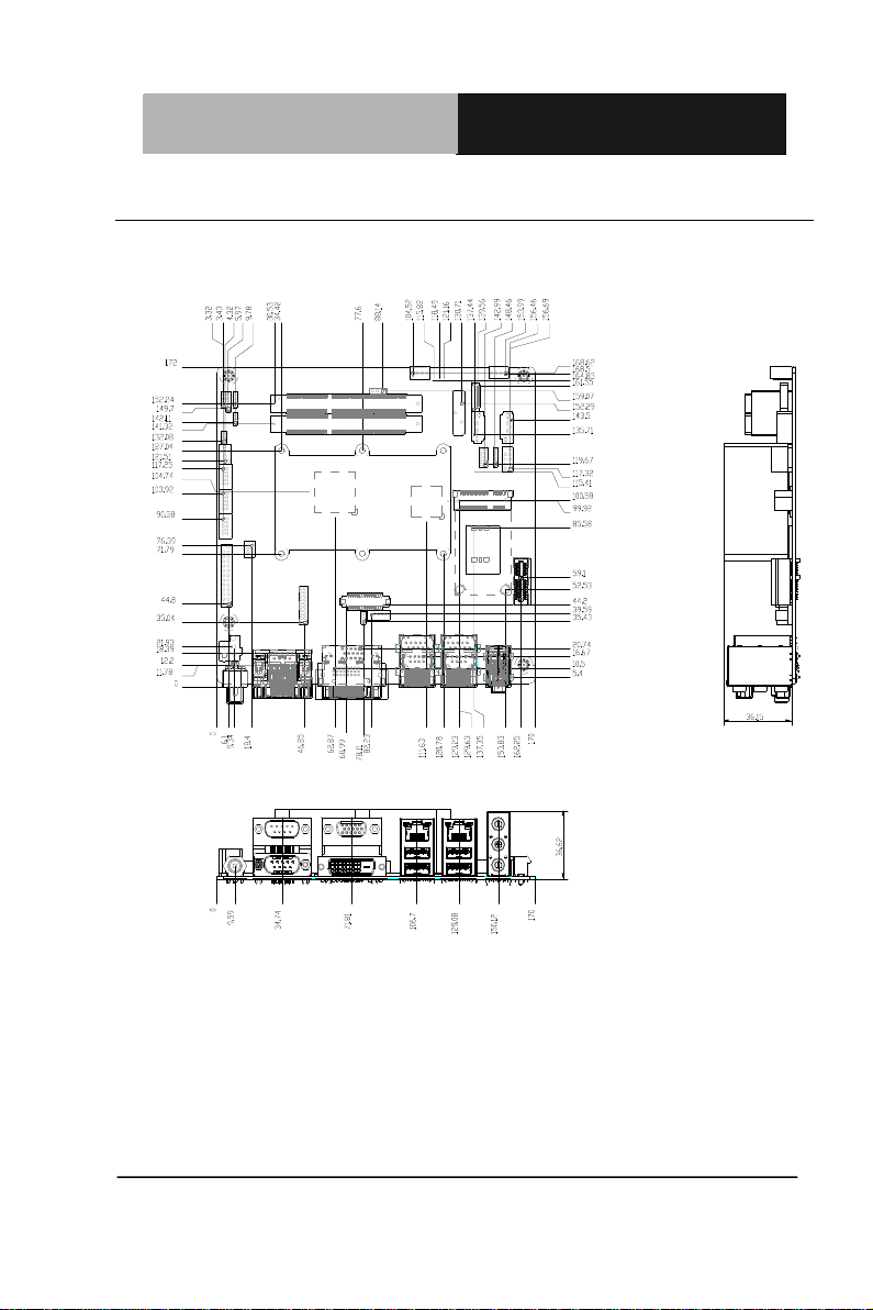
2.3 Mechanical Drawing
Component Side
Chapter 2 Quick Installation Guide 2 - 4
Page 16

Industrial Motherboard
EMB-CV1 series
Solder Side
Chapter 2 Quick Installation Guide 2 - 5
Page 17

Industrial Motherboard
EMB-CV1 series
Label
Function
ATMODE
AT/ATX Mode Selection
CLRTC
Clear COMS
DIGITALREFENCE
COM2 External Power Selection
LVDS_VDD_SEL
LVDS Panel Power Selection
L_BRIGHTNESS
LVDS Brightness Control Type Selection
LVDS_SWITCH
LVDS Function Enable
LCD_POWER_SEL
LVDS Panel Backlight Power Selection
WDT
Watchdog Timer Function Switch
2.4 List of Jumpers
The board has a number of jumpers that allow you to configure your
system to suit your application.
The table below shows the function of each of the board's jumpers:
Chapter 2 Quick Installation Guide 2 - 6
Page 18

Industrial Motherboard
EMB-CV1 series
Label
Function
DC_PWR
+12V Power connector
CON2
+12V AUX Power Connector
CHA_FAN
System FAN Connector
COM3
COM 3 Connector
COM4
COM 4 Connector
COM5
COM 5 Connector
CON1
SIM Card Socket
CPU_FAN
CPU FAN Connector
DIGITALREFENCE
GPIO/SM BUS/COM2/ COM2 External Power
Selection
F_PANEL
Front Panel Pin Header
KB/Ms
PS/2 Keyboard / Mouse Connector
LCD_POWER
LVDS Panel Power Connector
LPT
Parallel Port Connector
LVDS
LVDS Panel Connector
PCIEX1_1
PCI-E [x1] Slot
SATA_PWR1
Serial ATA Power Connector
SATA3G_1
SATA 0 Connector
SATA3G_2
SATA 1 Connector
2.5 List of Connectors
The board has a number of connectors that allow you to configure your
system to suit your application.
The table below shows the function of each of the board's connectors:
Chapter 2 Quick Installation Guide 2 - 7
Page 19

Industrial Motherboard
EMB-CV1 series
USB56
USB 5 & 6 Pin Header
USB7
USB 7 Pin Header
WLAN
Mini PCI-E Slot
NOTE: The +12V Power connector (Label: DC_PWR) is lockable Jack
type with screw. Please refer the inner and outer diameter
dimension of connector as below to choose suitable adaptor.
Chapter 2 Quick Installation Guide 2 - 8
Page 20

Industrial Motherboard
EMB-CV1 series
1
2
3
Open Closed Closed 2-3
2.6 Setting Jumpers
You configure your card to match the needs of your application by
setting jumpers. A jumper is the simplest kind of electric switch. It
consists of two metal pins and a small metal clip (often protected by a
plastic cover) that slides over the pins to connect them. To “close” a
jumper you connect the pins with the clip.
To “open” a jumper you remove the clip. Sometimes a jumper will have
three pins, labeled 1, 2 and 3. In this case you would connect either
pins 1 and 2 or 2 and 3.
A pair of needle-nose pliers may be helpful when working with jumpers.
If you have any doubts about the best hardware configuration for your
application, contact your local distributor or sales representative before
you make any change.
Generally, you simply need a standard cable to make most
connections.
Chapter 2 Quick Installation Guide 2 - 9
Page 21

Industrial Motherboard
EMB-CV1 series
ATOMODE
Function
Close 1-2
AT
Close 2-3
ATX Mode (Default)
CLRTC
Function
Close 1-2
Protected (Default)
Close 2-3
Clear
DIGITALREFENCE
Function
Close 15-16
+12V
Close 17-18
RI# (Default)
Close 19-20
+5V
LVDS_VDD_SEL
Function
Close 1-2
+3.3V (Default)
Close 2-3
+5V
L_BRIGHTNESS
Function
Close 1-2
Voltage Control (Default)
Close 2-3
PWM Control
2.7 AT/ATX Mode Selection (ATMODE)
2.8 Clear COMS (CLRTC)
2.9 COM2 External Power Selection (DIGITALREFENCE)
2.10 LVDS Panel Power Selection (LVDS_VDD_SEL)
2.11 LVDS Brightness Control Type Selection (L_BRIGHTNESS)
Chapter 2 Quick Installation Guide 2 - 10
Page 22

Industrial Motherboard
EMB-CV1 series
LVDS_SWITCH
Function
Close 1-2
Disable
Close 2-3
Enable (Default)
LCD_POWER_SEL
Function
Close 1-2
+12V
Close 2-3
+5V (Default)
WDT
Function
Close 1-2
Disable (Default)
Close 2-3
Enable
Pin
Signal
Pin
Signal
1
GND
2
GND
3
+12V
4
+12V
Pin
Signal
Pin
Signal
1
FAN Control
2
FAN Sense
3
+12V
4
GND
2.12 LVDS function Enable (LVDS_SWITCH)
2.13 LVDS Panel Backlight Power Selection (LCD_POWER_SEL)
2.14 Watchdog Timer Function Switch (WDT)
2.15 +12V AUX Power Connector (CON2)
2.16 CPU/SYSTEM FAN Connector (CPU_FAN/CHA_FAN)
Chapter 2 Quick Installation Guide 2 - 11
Page 23

Industrial Motherboard
EMB-CV1 series
Pin
Signal
Pin
Signal
1
DCD
2
RXD
3
TXD
4
DTR
5
GND
6
DSR
7
RTS
8
CTS
9
RI
10
NC
Pin
Signal
Pin
Signal
1
GP50
2
GP51
3
GP52
4
GP53
5
GP54
6
GP55
7
GP56
8
GP57
9
+5V
10
GND
11
SMB_CLOCK
12
SMB_DATA
13
+5V
14
GND
15
COM2_RI#
16
+12V
17
COM2_RI#
18
RI#
19
COM2_RI#
20
+5V
2.17 COM3/COM4/COM5 RS-232 Serial Port PIN HEADER
(COM3/COM4/COM5)
2.18 GPIO/SM BUS/COM2/ COM2 External Power Selection
(DIGTALREFENCE)
Chapter 2 Quick Installation Guide 2 - 12
Page 24

Industrial Motherboard
EMB-CV1 series
Pin
Signal
Pin
Signal
1
DCD (422TXD-/485DATA-)
2
RXD (422RXD+)
3
TXD (422TXD+/485DATA+)
4
DTR (422RXD-)
5
GND
6
DSR
7
RTS
8
CTS
9
RI/+12V/+5V
10
N.C.
Pin
Signal
Pin
Signal
1
HDDLED+
2
POWERLED+
3
HDDLED-
4
POWERLED-
5
RESET-
6
PWRBTN+
7
RESET+
8
PWRBTN-
9
N/C
Pin
Signal
Pin
Signal
1
KB_DATA
2
KB_CLK
3
GND
4
+5V
5
MS_DATA
6
MS_CLK
2.19 COM2 RS-232/422/485 connector
2.20 Front Panel Pin Header (F_PANEL)
2.21 PS/2 Keyboard/Mouse Connector (KB/MS)
Chapter 2 Quick Installation Guide 2 - 13
Page 25

Industrial Motherboard
EMB-CV1 series
Pin
Signal
Pin
Signal
1
Panel Power
2
Panel brightness control
3
GND
4
GND
5
Panel backlight control
Pin
Signal
Pin
Signal
1
STB#
2
AFD#
3
DATA 0
4
ERROR#
5
DATA 1
6
INIT#
7
DATA 2
8
SLIN#
9
DATA 3
10
GND
11
DATA 4
12
GND
13
DATA 5
14
GND
15
DATA 6
16
GND
17
DATA 7
18
GND
19
ACK#
20
GND
21
BUSY
22
GND
23
PE
24
GND
25
SLCT
2.22 LVDS Panel Power Connector (LCD_POWER)
2.23 Parallel Port Connector (LPT)
Chapter 2 Quick Installation Guide 2 - 14
Page 26

Industrial Motherboard
EMB-CV1 series
Pin
Signal
Pin
Signal
1
NC 2 NC 3 Panel power
4
GND
5
NC 6 NC 7 NC 8 NC 9 NC
10
NC
11
NC
12
NC
13
DDC_DATA
14
DDC_CLOCK
15
DATA3-
16
DATA3+
17
DATA2-
18
DATA2+
19
DATA1-
20
DATA1+
21
DATA0-
22
DATA0+
23
Panel power
24
GND
25
LVDS_CLOCK-
26
LVDS_CLOCK+
27
Panel power
28
GND
29
Backlight enable
30
Brightness control
2.24 LVDS Panel Connector (LVDS)
NOTE: LVDS connector Vendor:
Chapter 2 Quick Installation Guide 2 - 15
PINREX; Model: 712-76-30GWR8. Please refer the drawing
below, notice the location of PIN1, PIN2, PIN29 and PIN30.
Page 27

Industrial Motherboard
EMB-CV1 series
Pin
Signal
Pin
Signal
1
+5 2 GND
3
GND
4
+12V
Pin
Signal
Pin
Signal
1
+5V 2 GND
3
USBD-
4
GND
5
USBD+
6
USBD+
7
GND
8
USBD-
9
GND
10
+5V
1 2 29
30
VGA
DVI-D
COM
LAN
LAN
Audio
2.25 Serial ATA Power Connector (SATA_PWR1)
2.26 USB 5 & 6 PIN HEADER (USB56)
Chapter 2 Quick Installation Guide 2 - 16
Page 28

Industrial Motherboard
EMB-CV1 series
Pin
Signal
Pin
Signal
1
+5V 2 GND
3
USBD-
4
GND
5
USBD+
6
USBD+
7
GND
8
USBD-
9
GND
10
+5V
2.27 USB 7 PIN HEADER (USB7)
Chapter 2 Quick Installation Guide 2 - 17
Page 29

Industrial Motherboard
EMB-CV1 series
Chapter
3
AMI
BIOS Setup
Chapter 3 AMI BIOS Setup 3-1
Page 30

Industrial Motherboard
EMB-CV1 series
3.1 System Test and Initialization
These routines test and initialize board hardware. If the routines
encounter an error during the tests, you will either hear a few short
beeps or see an error message on the screen. There are two kinds
of errors: fatal and non-fatal. The system can usually continue the
boot up sequence with non-fatal errors.
System configuration verification
These routines check the current system configuration against the
values stored in the CMOS memory. If they do not match, the
program outputs an error message. You will then need to run the
BIOS setup program to set the configuration information in memory.
There are three situations in which you will need to change the
CMOS settings:
1. You are starting your system for the first time
2. You have changed the hardware attached to your system
3. The CMOS memory has lost power and the configuration
information has been erased.
The EMB-CV1 CMOS memory has an integral lithium battery
backup for data retention. However, you will need to replace the
complete unit when it runs down.
Chapter 3 AMI BIOS Setup 3-2
Page 31

Industrial Motherboard
EMB-CV1 series
3.2 AMI BIOS Setup
AMI BIOS ROM has a built-in Setup program that allows users to
modify the basic system configuration. This type of information is
stored in battery-backed CMOS RAM so that it retains the Setup
information when the power is turned off.
Entering Setup
Power on the computer and press <Del> or <F2> immediately. This
will allow you to enter Setup.
Main
Set the date, use tab to switch between date elements.
Advanced
Advanced BIOS Features Setup including TPM, ACPI, etc.
Chipset
Host bridge parameters.
Boot
Enabled / disabled quiet boot option.
Security
Set setup administrator password.
Save & Exit
Exit system setup after saving the changes.
Chapter 3 AMI BIOS Setup 3-3
Page 32

Industrial Motherboard
EMB-CV1 series
Chapter
4
0BDriver
Installation
.
Chapter 4 Driver Installation 4 -1
Page 33

Industrial Motherboard
EMB-CV1 series
The EMB-CV1 comes with an Autorun CD-ROM that contains all
drivers and utilities that can help you to install the driver
automatically.
Insert the driver CD, the driver CD-title will automatically start and
show the installation guide. If not, please follow the sequence below
to install the drivers.
Follow the sequence below to install the drivers:
Step 1 – Install Chipset Driver
Step 2 – Install VGA Driver
Step 3 – Install LAN Device
Step 4 – Install Audio Driver
Step 5 – Install AHCI Driver
Please read instructions below for further detailed installations.
Chapter 4 Driver Installation 4 -2
Page 34

Industrial Motherboard
EMB-CV1 series
4.1 Installation:
Insert the EMB-CV1 CD-ROM into the CD-ROM drive. And install
the drivers from Step 1 to Step 5 in order.
Step 1 – Install Chipset Driver
1. Click on the Step1-INF folder and double click on the
Setup.exe
2. Follow the instructions that the window shows
3. The system will help you install the driver automatically
Step 2 – Install VGA Driver
1. Click on the Step2-VGA folder and double click on the
Setup.exe
2. Follow the instructions that the window shows
3. The system will help you install the driver automatically
Step 3 –Install LAN Driver
1. Click on the Step3-LAN folder and double click on the
setup.exe
2. Follow the instructions that the window shows
3. The system will help you install the driver automatically
Step 4 –Install Audio Driver
1. Click on the Step4-Audio folder and double click on the
SETUP.exe
Chapter 4 Driver Installation 4 -3
Page 35

Industrial Motherboard
EMB-CV1 series
2. Follow the instructions that the window shows
3. The system will help you install the driver automatically
Step 5 –Install AHCI Driver
1. Click on the Step5-AHCI folder and select the folder of AP
2. Double click on the setup.exe
3. Follow the instructions that the window shows
4. The system will help you install the driver automatically
Chapter 4 Driver Installation 4 -4
Page 36

Industrial Motherboard
EMB-CV1 series
Appendix
A
Programming the
Watchdog Timer
Appendix A Programming the Watchdog Timer A-1
Page 37

Industrial Motherboard
EMB-CV1 series
A.1 Programming
EMB-CV1 utilizes ITE 8783 chipset as its watchdog
timer controller. Below are the procedures to complete its
configuration and this initial watchdog timer program is
also attached based on which you can develop
customized program to fit your application.
Configuring Sequence Description
After the hardware reset or power-on reset, the ITE 8783 enters the
normal mode with all logical devices disabled except
KBC. The initial state (enable bit ) of this logical device (KBC) is
determined by the state of pin 121 (DTR1#) at the falling edge of
the system reset during power-on reset.
Appendix A Programming the Watchdog Timer A-2
Page 38

Industrial Motherboard
EMB-CV1 series
There are three steps to complete the configuration setup: (1) Enter
the MB PnP Mode; (2) Modify the data of configuration registers; (3)
Exit the MB PnP Mode. Undesired result may occur if the MB PnP
Mode is not exited normally.
(1) Enter the MB PnP Mode
To enter the MB PnP Mode, four special I/O write operations are to
be performed during Wait for Key state. To ensure the initial state of
the key-check logic, it is necessary to perform four write opera-tions
to the Special Address port (2EH). Two different enter keys are
provided to select configuration ports (2Eh/2Fh) of the next step.
(2) Modify the Data of the Registers
All configuration registers can be accessed after entering the MB
PnP Mode. Before accessing a selected register, the content of
Index 07h must be changed to the LDN to which the register
belongs, except some Global registers.
(3) Exit the MB PnP Mode
Set bit 1 of the configure control register (Index=02h) to 1 to exit the
MB PnP Mode.
Appendix A Programming the Watchdog Timer A-3
Page 39

Industrial Motherboard
EMB-CV1 series
WatchDog Timer Configuration Registers
Configure Control (Index=02h)
This register is write only. Its values are not sticky; that is to say, a
hardware reset will automatically clear the bits, and does not
require the software to clear them.
Watch Dog Timer 1, 2, 3 Control Register (Index=71h,81h,91h
Default=00h)
Appendix A Programming the Watchdog Timer A-4
Page 40

Industrial Motherboard
EMB-CV1 series
Watch Dog Timer 1, 2, 3 Configuration Register (Index=72h,
82h, 92h Default=001s0000b)
Watch Dog Timer 1,2,3 Time-Out Value (LSB) Register
(Index=73h,83h,93h, Default=38h)
Watch Dog Timer 1,2,3 Time-Out Value (MSB) Register
(Index=74h,84h,94h Default=00h)
Appendix A Programming the Watchdog Timer A-5
Page 41

Industrial Motherboard
EMB-CV1 series
A.2 ITE8783 Watchdog Timer Initial Program
.MODEL SMALL
.CODE
Main:
CALL Enter_Configuration_mode
CALL Check_Chip
mov cl, 7
call Set_Logic_Device
;time setting
mov cl, 10 ; 10 Sec
dec al
Watch_Dog_Setting:
;Timer setting
mov al, cl
mov cl, 73h
call Superio_Set_Reg
;Clear by keyboard or mouse interrupt
mov al, 0f0h
mov cl, 71h
call Superio_Set_Reg
;unit is second.
mov al, 0C0H
mov cl, 72h
Appendix A Programming the Watchdog Timer A-6
Page 42

Industrial Motherboard
EMB-CV1 series
call Superio_Set_Reg
; game port enable
mov cl, 9
call Set_Logic_Device
Initial_OK:
CALL Exit_Configuration_mode
MOV AH,4Ch
INT 21h
Enter_Configuration_Mode PROC NEAR
MOV SI,WORD PTR CS:[Offset Cfg_Port]
MOV DX,02Eh
MOV CX,04h
Init_1:
MOV AL,BYTE PTR CS:[SI]
OUT DX,AL
INC SI
LOOP Init_1
RET
Enter_Configuration_Mode ENDP
Exit_Configuration_Mode PROC NEAR
MOV AX,0202h
Appendix A Programming the Watchdog Timer A-7
Page 43

Industrial Motherboard
EMB-CV1 series
CALL Write_Configuration_Data
RET
Exit_Configuration_Mode ENDP
Check_Chip PROC NEAR
MOV AL,20h
CALL Read_Configuration_Data
CMP AL,87h
JNE Not_Initial
MOV AL,21h
CALL Read_Configuration_Data
CMP AL,81h
JNE Not_Initial
Need_Initial:
STC
RET
Not_Initial:
CLC
RET
Check_Chip ENDP
Read_Configuration_Data PROC NEAR
MOV DX,WORD PTR CS:[Cfg_Port+04h]
Appendix A Programming the Watchdog Timer A-8
Page 44

Industrial Motherboard
EMB-CV1 series
OUT DX,AL
MOV DX,WORD PTR CS:[Cfg_Port+06h]
IN AL,DX
RET
Read_Configuration_Data ENDP
Write_Configuration_Data PROC NEAR
MOV DX,WORD PTR CS:[Cfg_Port+04h]
OUT DX,AL
XCHG AL,AH
MOV DX,WORD PTR CS:[Cfg_Port+06h]
OUT DX,AL
RET
Write_Configuration_Data ENDP
Superio_Set_Reg proc near
push ax
MOV DX,WORD PTR CS:[Cfg_Port+04h]
mov al,cl
out dx,al
pop ax
inc dx
out dx,al
ret
Superio_Set_Reg endp.Set_Logic_Device proc near
Appendix A Programming the Watchdog Timer A-9
Page 45

Industrial Motherboard
EMB-CV1 series
Set_Logic_Device proc near
push ax
push cx
xchg al,cl
mov cl,07h
call Superio_Set_Reg
pop cx
pop ax
ret
Set_Logic_Device endp
;Select 02Eh->Index Port, 02Fh->Data Port
Cfg_Port DB 087h,001h,055h,055h
DW 02Eh,02Fh
END Main
Note: Interrupt level mapping
0Fh-Dh: not valid
0Ch: IRQ12
.
.
03h: IRQ3
02h: not valid
01h: IRQ1
00h: no interrupt selected
Appendix A Programming the Watchdog Timer A-10
Page 46

Industrial Motherboard
EMB-CV1 series
Appendix
B
Mating
Connector
Appendix B Mating Connector B - 1
Page 47

Industrial Motherboard
EMB-CV1 series
Connector
Label
Function
Mating Connector
Available
Cable
Cable
P/N
Vendor
Model No.
CON2
+12V AUX
power
connector
PINREX
POWER CON 4P
S/T,ATX,W/PG2
PINREX/740-41-0
4TWC0.DIP
CHA_FAN
System
FAN
connector
PINREX
WAFER HD 4P
S/T 2.54MM
L-GRAY
PINREX/744-81-0
4TG20 [EL].DIP
COM3
COM 3
connector
CATCH
(TF)BOX
HEADER.5*2P.18
0D.(M).2.0mm.DI
P.WO
PIN10.CATCH.11
47-000-10SA
COM4
COM 4
connector
CATCH
(TF)BOX
HEADER.5*2P.18
0D.(M).2.0mm.DI
P.WO
PIN10.CATCH.11
47-000-10SA
COM5
COM 5
connector
CATCH
(TF)BOX
HEADER.5*2P.18
0D.(M).2.0mm.DI
P.WO
PIN10.CATCH.11
47-000-10SA
CON1
SIM card
socket
HAMBUR
G
SIM CON 6P 2.54
PITCH SMT
HAMBURG/ICA-5
09.SMD
B.1 List of Mating Connectors and Cables
The table notes mating connectors and available cables.
Appendix B Mating Connector B - 2
Page 48

Industrial Motherboard
EMB-CV1 series
CPU_FAN
CPU FAN
connector
PINREX
WAFER HD 4P
S/T 2.54MM
L-GRAY
PINREX/744-81-0
4TG20 [EL].DIP
DIGITALREF
ENCE
GPIO/SM
BUS/COM2
/ COM2
external
power
select
JVE
HEADER
2X10P,S/T,2.0mm
,STACK
JVE/21N22050-2
0S22B01G4/9.2/2
.DIP
F_PANEL
Front panel
pin header
PINREX
HEADER 2X5P
2.54mm S/T.K10
G/F
PINREX/210-92-0
5GB02
KB/MS
PS/2
Keyboard /
Mouse
connector
Ho-Base
(TF)WAFER
BOX.6P.180D(M).
2.0mm.W/LOCK
DIP.何
迪.2005-2WS-6
LCD_POWE
LVDS panel
power
connector
CATCH
(TF)WAFER
BOX.5P.180D.(M)
.2.0mm.W/LOCK
DIP.CATCH.1192700-05S
LPT
Parallel port
connector
PINREX
HEADER
2X13P,S/T,2.54m
m,K26
PINREX/210-92-1
3GB11 [EL].DIP
LVDS
LVDS panel
connector
E-call
(TF)Board-Wire
Connector.30P.18
0D(M).SMD.Pitch
=1.25mm.W/Reinf
orcem.E-call.0110
-01-553-300
PCIEX1_1
PCI-E X1
slot
E-MOVE
SLOT 36P G/F
PCIE X1,DARK
Appendix B Mating Connector B - 3
Page 49

Industrial Motherboard
EMB-CV1 series
BLUE
E-MOVE/EE0360
-1GGZ-00H
[GA].DIP
SATA_PWR1
Serial ATA
power
Connector
CATCH
(TF)WAFER.4P.1
80D.(M).2.5mm.
W/LOCK POWER
DIP.CATCH.1198700-04S.
SATA3G_1
SATA 0
Connector
LOTES
SATA CON 7P
S/T
G/F,DIP,CHARL
LOTES/ABA-SAT046-K13.DIP
SATA3G_2
SATA 1
Connector
LOTES
SATA CON 7P
S/T
G/F,DIP,CHARL
LOTES/ABA-SAT046-K13.DIP
USB56
USB 5 & 6
pin header
JVE
(TF)PIN
HEADER.5*2P.18
0D.(M).2.0mm.DI
P
WLAN
Mini PCI-E
SLOT
LOTES
MINI PCI-E
52P,0.8MM,9.0H
SMT
LOTES/AAA-PCI047-P01
[HF].SMD
Note: The Cable P/N with “ * ” sign is for WiTAS series products.
Appendix B Mating Connector B - 4
 Loading...