

Page 1
ETX Carrier Board ECB-902M
Installation
Chapter
1
Quick
Guide
Part No. 2007902M20 Printed in Taiwan June 2009
Chapter 1 Quick Installation Guide 1-1
Page 2
ETX Carrier Board ECB-902M
1.1 Safety Precaution
Always completely disconnect the power cord
from your board whenever you are working on
it. Do not make connections while the power is
on, because a sudden rush of power can
damage sensitive electronic components.
Always ground yourself to remove any static
charge before touching the board. Modern
electronic devices are very sensitive to static
electric charges. Use a grounding wrist strap at
all times. Place all electronic components on a
static-dissipative surface or in a static-shielded
bag when they are not in the chassis
Chapter 1 Quick Installation Guide 1-2
Page 3
ETX Carrier Board ECB-902M
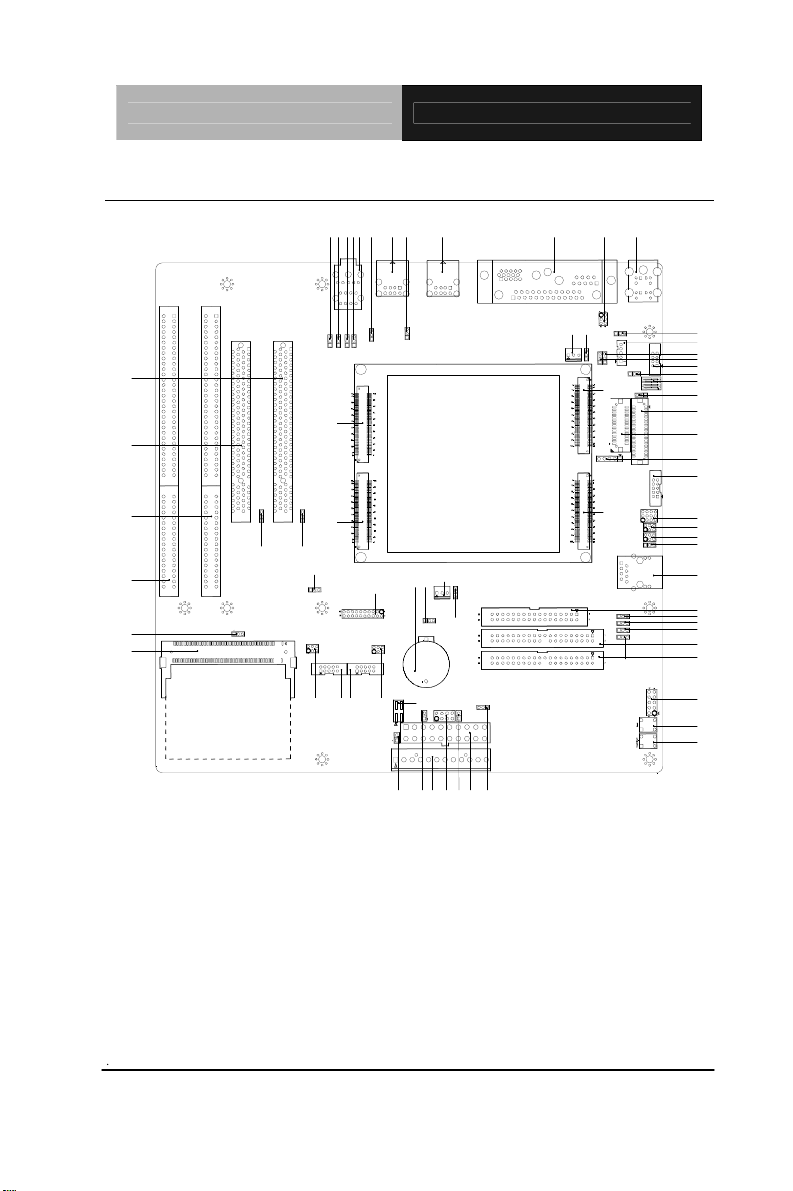
1.2 Location of Jumpers and Connectors
PCI1
PCI2
CN4
CN3
JP24
CN29
JP34
JP35
ETX-1
ETX-2
JP6
JP5
JP10
JP27
CN19
JP23
JP37
JP33
JP36
CN20
CN25
CN27
A
B
CN23
BT1
JP9
CN7
JP21
JP30
JP26
CN18
P20
P31
P28
P32
P29
CN22
CN21
CN13
CN24
C
D
CN8
JP14
JP22
ETX-3
ETX-4
JP4
JP25
CN12
JP11
JP13
CN9
JP15
SW3
JP12
CN10
CN11
CN6
CN17
J16
JP18
JP19
JP17
CN26
CN16
JP1
JP2
JP3
IDE1
IDE2
JP8
SW2
SW1
Chapter 1 Quick Installation Guide 1-3
Page 4
ETX Carrier Board ECB-902M
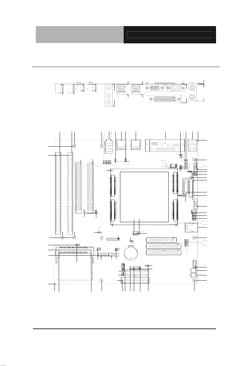
1.3 Mechanical Drawing
17.30
17.30
37.50
11.00
11.00
15.00
15.00
28.50 1.60
31.60
10.16
25.40
165.10
177.55
186.16
195.31
243.84
209.55
214.66
234.98
199.12
229.87
243.84
236.42
193.04
209.55
156.46
206.22
160.05
148.51
151.29
163.83
140.11
178.80
39.36
41.28
50.92
A
B
123.16
169.39
173.23
145.18
185.99
163.83
138.88
147.00
170.48
164.53
222.10
228.47
237.69
181.41
163.83
130.01
135.27
166.89
128.46
105.69
122.94
35.78
36.39
99.82
108.71
155.73
157.92
114.27
171.20
98.20
108.81
114.73
123.55
84.44
55.53
24.92
44.13
45.94
47.59
212.65
218.03
45.47
C
93.73 93.77
D
9.43
0.00
29.70
20.16
22.47
0.00
2.81
36.83
22.38
27.94
30.23
20.57
37.18
21.16
33.02
15.74
47.05
49.23
53.11
57.66
63.25
67.52
67.74
87.74
9.05
111.82
123.03
127.62
132.19
135.00
140.92
148.08
165.10
169.16
172.47
175.77
215.39
220.98
228.85
237.49
6.35
Chapter 1 Quick Installation Guide 1-4
Page 5

ETX Carrier Board ECB-902M
1.4 List of Jumpers
The board has a number of jumpers that allow you to configure your
system to suit your application.
The table below shows the function of each of the board's jumpers:
Jumpers
Label Function
JP1 ETX-4 Pin D9 Selection
JP2 ETX-4 Pin D26 Selection
JP3 ETX-4 Pin D35 Selection
JP4 ETX-4 Pin D90 Selection
JP5 PCI1 IDSEL Selection
JP6 PCI2 IDSEL Selection
JP9 Clear CMOS Selection
JP10 WDT Reset Selection
JP11 Backlight Enabled Voltage Selection
JP12 LCD Input Voltage Selection
JP13 Backlight Power Selection
JP14 COM 1 +12V/+5V/Ring Selection
JP15 LVDS, TTL or DVI Selection
J16 COM2 RS-232/422/485 Selection
JP17 PME and Ring Selection
JP18 COM2 RS-232/422/485 Selection
JP19 COM 2 +12V/+5V/Ring Selection
JP20 AT and ATX Type Power Supply Selection
JP21 CPU Fan Power Selection
JP22 System Fan Power Selection
Chapter 1 Quick Installation Guide 1-5
Page 6

ETX Carrier Board ECB-902M
JP23 USB Enable Selection
JP24 Mini PCI IDSEL Selection
JP25 LCD Backlight Enable Selection
JP26 COM 3 +12V/+5V/Ring Selection
JP27 COM 4 +12V/+5V/Ring Selection
JP28 +5V Power Consumption Measure
JP29 +12V Power Consumption Measure
JP30 +3.3V Power Consumption Measure
JP31 -5V Power Consumption Measure
JP32 -12V Power Consumption Measure
JP33 Audio Line-in (R) Input Cap Selection
JP34 Audio Line-in (L) Input Cap Selection
JP35 Audio Line-out (R) Output Cap Selection
JP36 Audio Line-out (L) Output Cap Selection
JP37 Audio MIC Input Cap Selection
Chapter 1 Quick Installation Guide 1-6
Page 7

ETX Carrier Board ECB-902M
1.5 List of Connectors
The board has a number of connectors that allow you to configure
your system to suit your application. The table below shows the
function of each board's connectors:
Label
CN3 ISA Slot
CN4 ISA Slot
CN6 IR Connector
CN7 DIGITAL I/O Connector
CN8 PS2 KB / MS Connector
CN9 TV-OUT Connector
CN10 TTL LCD Connector
CN11 LVDS Connector
CN12 LCD Inverter Power Connector
CN13 COM1 / Printer / VGA Connector
CN16 Floppy Connector
CN17 COM2 Connector
CN18 COM3 Connector
CN19 COM4 Connector
CN20 Audio Connector
CN21 ATX Power Connector
CN22 AT Power Connector
CN23 CPU FAN Connector
CN24 System FAN Connector
CN25 USB Connector
CN26 LAN Connector
CN27 USB Connector
CN29 Mini PCI Connector
Function
Chapter 1 Quick Installation Guide 1-7
Page 8
ETX Carrier Board ECB-902M
PCI1 PCI Connector
PCI2 PCI Connector
IDE1 Primary IDE Connector
IDE2 Secondary IDE Connector
JP8 Front Panel Connector
SW1 Power Button Switch
SW2 Hardware Reset Switch
SW3 TV-OUT or TTL Selection Switch
Chapter 1 Quick Installation Guide 1-8
Page 9
ETX Carrier Board ECB-902M
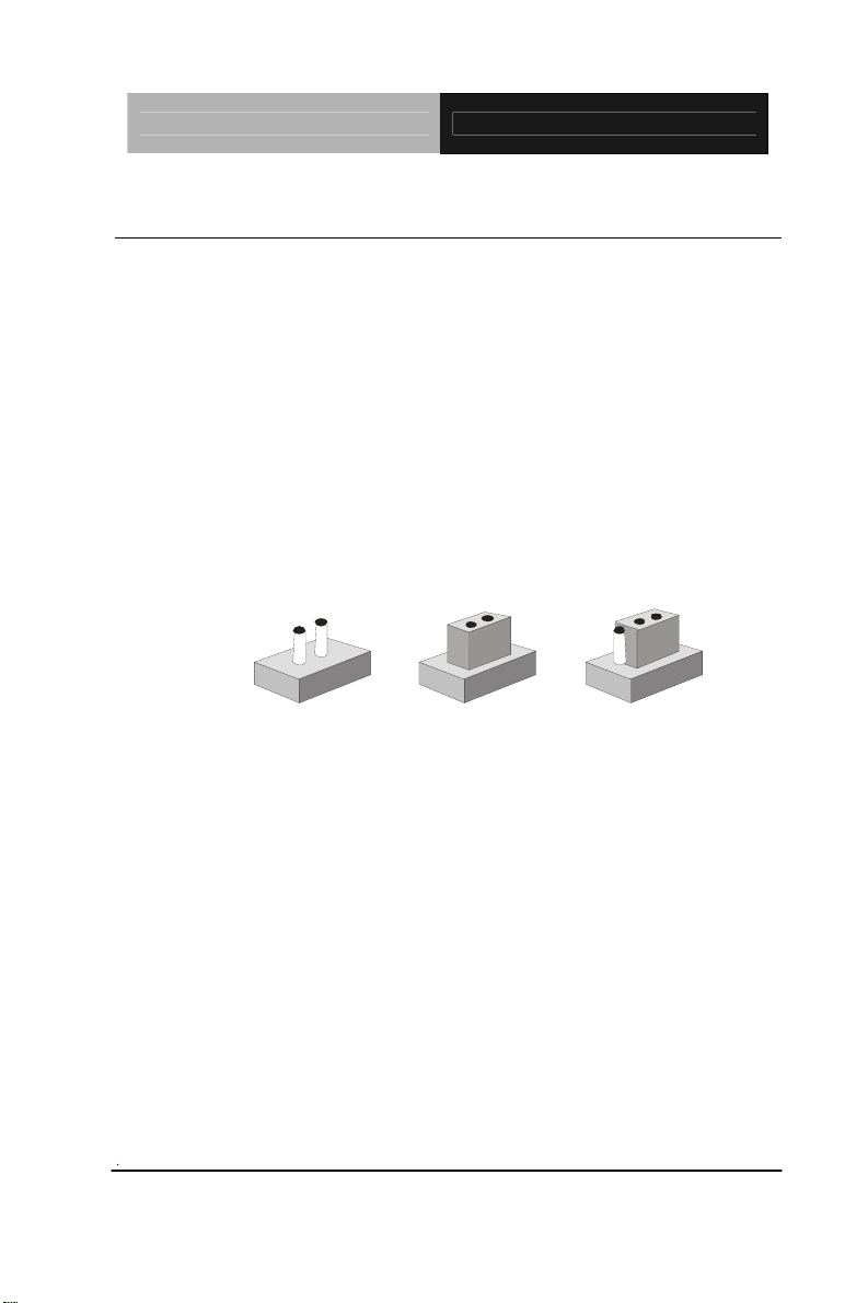
1.6 Setting Jumpers
You configure your card to match the needs of your application by
setting jumpers. A jumper is the simplest kind of electric switch. It
consists of two metal pins and a small metal clip (often protected by
a plastic cover) that slides over the pins to connect them. To “close”
a jumper you connect the pins with the clip.
To “open” a jumper you remove the clip. Sometimes a jumper will
have three pins, labeled 1, 2 and 3. In this case you would connect
either pins 1 and 2 or 2 and 3.
3
2
1
Open Closed Closed 2-3
A pair of needle-nose pliers may be helpful when working with
jumpers.
If you have any doubts about the best hardware configuration for
your application, contact your local distributor or sales
representative before you make any change.
Generally, you simply need a standard cable to make most
connections.
Chapter 1 Quick Installation Guide 1-9
Page 10

ETX Carrier Board ECB-902M
1.7 ETX-4 Pin D9 Selection (JP1)
JP1 Function
1-2 CPU FAN (Default)
2-3 N.C.
1.8 ETX-4 Pin D26 Selection (JP2)
JP2 Function
1-2 CPU FAN
2-3 N.C. (Default)
1.9 ETX-4 Pin D35 Selection (JP3)
JP3 Function
1-2 Primary IDE ATA33/100 Detect (Default)
2-3 Secondary IDE ATA33/100 Detect
1.10 ETX-4 Pin D90 Selection (JP4)
JP4 Function
1-2 RING#
2-3 Primary IDE ATA33/100 Detect (Default)
1.11 PCI1 IDSEL Selection (JP5)
JP5 Function
1-2 AD19(Default)
2-3 AD28
1.12 PCI2 IDSEL Selection (JP6)
JP6 Function
1-2 AD20(Default)
Chapter 1 Quick Installation Guide 1-10
Page 11

ETX Carrier Board ECB-902M
2-3 AD29
1.13Clear CMOS Selection (JP9)
JP9 Function
1-2 Normal (Default)
2-3 Clear CMOS
1.14 WDT Reset Selection (JP10)
JP10 Function
1-2 Normal (Default)
2-3 WDT Reset(For ETX-625)
1.15 Backlight Enabled Voltage Selection (JP11)
JP11 Function
1-2 +5V
2-3 +3.3V (Default)
1.16 LCD Input Voltage Selection (JP12)
JP12 Function
1-2 +5V
2-3 +3.3V (Default)
1.17 Backlight Power Selection (JP13)
JP13 Function
1-2 +12V
2-3 +5V (Default)
Chapter 1 Quick Installation Guide 1-11
Page 12

ETX Carrier Board ECB-902M
1.18 COM1 +12V/+5V/Ring Selection (JP14)
JP14 Function
1-2 +12V
3-4 +5V
5-6 Ring (Default)
1.19 LVDS, TTL or DVI Selection (JP15)
JP15 Function
1-2 LVDS, TTL(Default)
2-3 DVI (For ETX-CX700M)
1.20 COM2 RS-232/422/485 Selection (J16/ JP18)
J16 JP18 Function
1-2,4-5,7-8,10-11 1-2 RS-232(Default)
2-3,5-6,8-9,11-12 3-4 RS-422
2-3,5-6,8-9,11-12 5-6 RS-485
1.21 PME and Ring Selection (JP17)
JP17 Function
1-2 RING#(Default)
2-3 PME#
1.22 COM 2 +12V/+5V/Ring Selection (JP19)
JP19 Function
1-2 +12V
3-4 +5V
5-6 Ring (Default)
Chapter 1 Quick Installation Guide 1-12
Page 13

ETX Carrier Board ECB-902M
1.23 AT and ATX Type Power Supply Selection (JP20)
JP20 Function
1-2 AT
2-3 ATX (Default)
1.24 CPU FAN Power Selection (JP21)
JP21 Function
1-2 +12V
2-3 +5V(Default)
1.25 System FAN Power Selection (JP22)
JP22 Function
1-2 +12V
2-3 +5V(Default)
1.26 USB Enable Selection (JP23)
JP23 Function
1-2 For 852GM chipset(For ETX-821, ETX-855)
2-3 Normal(Default)
1.27 Mini PCI IDSEL Selection (JP24)
JP24 Function
1-2 AD21(Default)
2-3 AD30
1.28 LCD Backlight Enable Selection (JP25)
JP25 Function
1-2 BLON#
Chapter 1 Quick Installation Guide 1-13
Page 14

ETX Carrier Board ECB-902M
2-3 BLON(Default)
1.29 COM3 +12/+5V/Ring Selection (JP26)
JP26 Function
1-2 +12V
3-4 +5V
5-6 Ring(Default)
1.30 COM4 +12/+5V/Ring Selection (JP27)
JP27 Function
1-2 +12V
3-4 +5V
5-6 Ring(Default)
1.31 +5V Power Consumption Measure (JP28)
JP28 Function
1-2 +5V
3-4 +5V
5-6 +5V
7-8 +5V
1.32 +12V Power Consumption Measure (JP29)
JP29 Function
1-2 +12V
1.33 +3.3V Power Consumption Measure (JP30)
JP30 Function
1-2 +3.3V
Chapter 1 Quick Installation Guide 1-14
Page 15

ETX Carrier Board ECB-902M
3-4 +3.3V
1.34 -5V Power Consumption Measure (JP31)
JP31 Function
1-2 -5V
1.35 -12V Power Consumption Measure (JP32)
JP32 Function
1-2 -12V
1.36 Audio Line-in (R) Input Cap Selection (JP33)
JP33 Function
1-2 Input filter cap(Default)
2-3 No input filter cap
1.37 Audio Line-in (L) Input Cap Selection (JP34)
JP34 Function
1-2 Input filter cap(Default)
2-3 No input filter cap
1.38 Audio Line-out (R) Output Cap Selection (JP35)
JP35 Function
1-2 Output filter cap(Default)
2-3 No output filter cap
1.39 Audio Line-out (L) Output Cap Selection (JP36)
JP36 Function
1-2 Output filter cap(Default)
Chapter 1 Quick Installation Guide 1-15
Page 16

ETX Carrier Board ECB-902M
2-3 No output filter cap
1.40 Audio MIC Input Cap Selection (JP37)
JP37 Function
1-2 Input filter cap(Default)
2-3 No input filter cap
Note:
JP33-JP37(For ETX-625,ETX-821,ETX-855,ETX-700,ETX-700B,
ETX-701, ETX-CX700M,please use Default.)
1.41 ISA Connector (CN3, CN4)
Standard ISA Slot
1.42 IR Connector (CN6)
Pin Signal
1 +5V
2 N.C.
3 IRRX
4 GND
5 IRTX
1.43 Digital I/O Connector (CN7)
Pin Signal Pin Signal
1 OUT0 2 OUT1
3 OUT2 4 OUT3
5 OUT4 6 OUT5
7 OUT6 8 OUT7
Chapter 1 Quick Installation Guide 1-16
Page 17

ETX Carrier Board ECB-902M
9 GND 10 GND
11 IN0 12 IN1
13 IN2 14 IN3
15 IN4 16 IN5
17 IN6 18 IN7
19 +5V 20 +12V
Note: The interrupt address is 200H.
1.44 PS2 KB / MS Connector (CN8)
Pin Signal Pin Signal
1 KBDAT 2 MSDAT
3 GND 4 +5V
5 KBCLK 6 MSCLK
7 MSDAT 8 N.C.
9 GND 10 +5V
11 MSCLK 12 N.C.
1.45 TV-OUT Connector (CN9)
Pin Signal Pin Signal
1 Y 2 CVBS
3 GND 4 GND
5 C 6 N.C.
7 GND 8 CSYNC
1.46 TTL LCD Connector (CN10)
Pin Signal Pin Signal
1 +5V 2 +5V
3 GND 4 GND
Chapter 1 Quick Installation Guide 1-17
Page 18

ETX Carrier Board ECB-902M
5 +3.3V 6 +3.3V
7 Backlight enable 8 GND
9 B0 10 B1
11 B2 12 B3
13 B4 14 B5
15 B6 16 B7
17 G0 18 G1
19 G2 20 G3
21 G4 22 G5
23 G6 24 G7
25 R0 26 R1
27 R2 28 R3
29 R4 30 R5
31 R6 32 R7
33 GND 34 GND
35 LCD CLOCK 36 LCD VSYNC
37 LCD DE 38 LCD HSYNC
39 N.C. 40 N.C.
1.47 LVDS Connector (CN11)
Pin Signal Pin Signal
1 Backlight enable 2 Backlight control
3 LVDS Power 4 GND
5 TX1CLK# 6 TX1CLK
7 LVDS Power 8 GND
9 TX1OUT#0 10 TX1OUT0
11 TX1OUT#1 12 TX1OUT1
13 TX1OUT#2 14 TX1OUT2
15 TX1OUT#3 16 TX1OUT3
Chapter 1 Quick Installation Guide 1-18
Page 19

ETX Carrier Board ECB-902M
17 DDC_DAT 18 DDC_CLK
19 TX2OUT#0 20 TX2OUT0
21 TX2OUT#1 22 TX2OUT1
23 TX2OUT#2 24 TX2OUT2
25 TX2OUT#3 26 TX2OUT3
27 LVDS Power 28 GND
29 TX2CLK# 30 TX2CLK
1.48 LCD Inverter Power Connector (CN12)
Pin Signal
1 LCD Inverter Power
2 Backlight control
3 GND
4 GND
5 Backlight enable
1.49 COM1 / Printer / VGA Connector (CN13)
Pin Signal Pin Signal
A1 #STROBE A14 #AFD
A2 PTD0 A15 #ERROR
A3 PTD 1 A16 #INIT
A4 PTD 2 A17 #SLIN
A5 PTD 3 A18 GND
A6 PTD 4 A19 GND
A7 PTD 5 A20 GND
A8 PTD 6 A21 GND
A9 PTD 7 A22 GND
A10 #ACK A23 GND
A11 BUSY A24 GND
Chapter 1 Quick Installation Guide 1-19
Page 20

ETX Carrier Board ECB-902M
A12 PE A25 GND
A13 SELECT
B1 DCD B2 RXD
B3 TXD B4 DTR
B5 GND B6 DSR
B7 RTS B8 CTS
B9 RING
C1 RED C2 GREEN
C3 BLUE C4 N.C.
C5 GND C6 GND
C7 GND C8 GND
C9 +5V C10 CRT_PLUG#
C11 N.C. C12 DDCDATA
C13 HSYNC C14 VSYNC
C15 DDCCLK
1.50 Floppy Connector (CN16)
Pin Signal Pin Signal
1 GND 2 #AFD
3 GND 4 N.C.
5 GND 6 N.C.
7 GND 8 PRD0
9 GND 10 PRD6
11 GND 12 #ACK
13 GND 14 PRD 7
15 GND 16 BUSY
17 GND 18 #INIT
19 GND 20 #SLIN
21 GND 22 PE
Chapter 1 Quick Installation Guide 1-20
Page 21

ETX Carrier Board ECB-902M
23 GND 24 SELECT
25 GND 26 PRD1
27 GND 28 PRD2
29 GND 30 PRD3
31 GND 32 #ERROR
33 N.C. 34 PRD4
1.51 COM2 Connector (CN17)
RS-232 Mode
Pin Signal Pin Signal
1 DCD 2 RXD
3 TXD 4 DTR
5 GND 6 DSR
7 RTS 8 CTS
9 RING/+5V/+12V 10 N.C.
RS-422 Mode
Pin Signal Pin Signal
1 TXD- 2 RXD+
3 TXD+ 4 RXD5 GND 6 N.C.
7 N.C. 8 N.C.
9 N.C. /+5V/+12V 10 N.C.
RS-485 Mode
Pin Signal Pin Signal
1 TXD- 2 N.C.
3 TXD+ 4 N.C.
5 GND 6 N.C.
Chapter 1 Quick Installation Guide 1-21
Page 22

ETX Carrier Board ECB-902M
7 N.C. 8 N.C.
9 N.C. /+5V/+12V 10 N.C.
1.52 COM3 / COM4 Connector (CN18, CN19)
Pin Signal Pin Signal
1 DCD 2 RXD
3 TXD 4 DTR
5 GND 6 DSR
7 RTS 8 CTS
9 RING/+5V/+12V 10 N.C.
1.53 Audio Connector (CN20)
Pin Signal Pin Signal
A1 LINL A2 GNDAUD
A3 GNDAUD A4 LINR
B1 LOUTL B2 GNDAUD
B3 GNDAUD B4 LOUTR
C0 GNDAUD C1 N.C.
C2 GNDAUD C3 GNDAUD
C4 MIC_IN
H1 GNDAUD H2 GNDAUD
H3 GNDAUD H4 GNDAUD
H5 GNDAUD
1.54 ATX Power Connector (CN21)
Pin Signal Pin Signal
1 N.C. 11 N.C.
2 N.C. 12 -12V
Chapter 1 Quick Installation Guide 1-22
Page 23

ETX Carrier Board ECB-902M
3 GND 13 GND
4 +5V 14 PSON#
5 GND 15 GND
6 +5V 16 GND
7 GND 17 GND
8 N.C. 18 -5V
9 5VSB 19 +5V
10 +12V 20 +5V
1.55 AT Power Connector (CN22)
Pin Signal
1 N.C.
2 +5V
3 +12V
4 -12V
5 GND
6 GND
7 GND
8 GND
9 -5V
10 +5V
11 +5V
12 +5V
1.56 CPU FAN Connector (CN23)
Pin Signal
1 GND
2 FAN Power
3 FAN Speed Sense
Chapter 1 Quick Installation Guide 1-23
Page 24

ETX Carrier Board ECB-902M
1.57 System FAN Connector (CN24)
Pin Signal
1 GND
2 FAN Power
3 N.C.
1.58 USB Connector (CN25)
Pin Signal Pin Signal
1 USB Power 2 USBD13 USBD1+ 4 GND
5 USB Power 6 USBD07 USBD0+ 8 GND
9 GND 10 GND
11 GND 12 GND
1.59 LAN Connector (CN26)
Pin Signal Pin Signal
1 RXD- 2 RXD+
3 TCD1 4 N.C
5 N.C 6 N.C.
7 TXD- 8 TXD+
9 TXRX_LED 10 LILED
11 LINK100_LED 12 GND
13 GND 14 GND
1.60 USB Connector (CN27)
Pin Signal Pin Signal
1 USB Power 2 USBD3-
Chapter 1 Quick Installation Guide 1-24
Page 25

ETX Carrier Board ECB-902M
3 USBD3+ 4 GND
5 USB Power 6 USBD27 USBD2+ 8 GND
9 GND 10 GND
11 GND 12 GND
1.61 Mini PCI Connector (CN29)
Standard Mini PCI Slot
1.62 PCI Connector (PCI1,PCI2)
Standard PCI Slot
1.63 Primary IDE Connector (IDE1)
Pin Signal Pin Signal
1 IDERST# 2 GND
3 PDD7 4 PDD8
5 PDD6 6 PDD9
7 PDD5 8 PDD10
9 PDD4 10 PDD11
11 PDD3 12 PDD12
13 PDD2 14 PDD13
15 PDD1 16 PDD14
17 PDD0 18 PDD15
19 GND 20 N.C.
21 PDDREQ 22 GND
23 PDIOW# 24 GND
25 PDIOR# 26 GND
27 PDRDY 28 PDCSEL
29 PDDACK# 30 GND
Chapter 1 Quick Installation Guide 1-25
Page 26

ETX Carrier Board ECB-902M
31 PIDEIRQ 32 N.C.
33 PDDA1 34 PD_80P
35 PDDA0 36 PDDA2
37 PDDCS1# 38 PDDCS#3
39 DASP# 40 GND
1.64 Secondary IDE Connector (IDE2)
Pin Signal Pin Signal
1 IDERST# 2 GND
3 SDD7 4 SDD8
5 SDD6 6 SDD9
7 SDD5 8 SDD10
9 SDD4 10 SDD11
11 SDD3 12 SDD12
13 SDD2 14 SDD13
15 SDD1 16 SDD14
17 SDD0 18 PDD15
19 GND 20 N.C.
21 SDDREQ 22 GND
23 SDIOW# 24 GND
25 SDIOR# 26 GND
27 SDRDY 28 SDCSEL
29 SDDACK# 30 GND
31 SIDEIRQ 32 N.C.
33 SDDA1 34 SD_80P
35 SDDA0 36 SDDA2
37 SDDCS1# 38 SDDCS#3
39 DASP# 40 GND
Chapter 1 Quick Installation Guide 1-26
Page 27

ETX Carrier Board ECB-902M
1.65 Front Panel Connector (JP8)
Pin Signal Pin Signal
1 PW- 2 PW+
3 IDE HDD LED- 4 IDE HDD LED+
5 Speaker- 6 Speaker+
7 Power LED- 8 Power LED+
9 RES- 10 RES+
1.66 SW1 Connector (SW1)
Power Button Switch
1.67 SW2 Connector (SW2)
Hardware Reset Switch
1.68 TV-OUT or TTL Selection Switch (SW3)
Switch Position Note
1 On for TV, Off for TTL
2 On for TV, Off for TTL
3 On for TV, Off for TTL
4 On for TV, Off for TTL
Chapter 1 Quick Installation Guide 1-27
Page 28

ETX Carrier Board ECB-902M
Below Table for China RoHS Requirements
产品中有毒有害物质或元素名称及含量
AAEON Main Board/ Daughter Board/ Backplane
有毒有害物质或元素
部件名称
印刷电路板
及其电子组件
外部信号
连接器及线材
O:表示该有毒有害物质在该部件所有均质材料中的含量均在
SJ/T 11363-2006 标准规定的限量要求以下。
X:表示该有毒有害物质至少在该部件的某一均质材料中的含量超出
SJ/T 11363-2006 标准规定的限量要求。
备注:此产品所标示之环保使用期限,系指在一般正常使用状况下。
铅
(Pb)汞 (Hg)镉 (Cd)
× ○ ○ ○ ○ ○
× ○ ○ ○ ○ ○
六价铬
(Cr(VI))
多溴联苯
(PBB)
多溴二苯醚
(PBDE)
Chapter 1 Quick Installation Guide 1-28
 Loading...