

Page 1

Advanced System
Controller
A I S - E1- H 6 1 A
AIS-E1-H61A
Advanced System Controller
3.5” HDD x 1, 2.5” HDD/SSD x 1
or 2.5” HDD/SSD x 2
Gigabit Ethernet x 2
COM x 6, USB2.0 x 8, CF-SATA x 1
Mini PCI-E x 1, PCI-E[x4] x 1
HD Audio Codec
AIS-E1 Manual 1st Ed.
September 2013
Page 2

Advanced System
Controller
A I S - E1- H 6 1 A
TCopyright Notice
This document is copyrighted, 2013. All rights are reserved. The
original manufacturer reserves the right to make improvements to
the products described in this manual at any time without notice.
No part of this manual may be reproduced, copied, translated, or
transmitted in any form or by any means without the prior written
permission of the original manufacturer. Information provided in
this manual is intended to be accurate and reliable. However, the
original manufacturer assumes no responsibility for its use, or for
any infringements upon the rights of third parties that may result
from its use.
The material in this document is for product information only and is
subject to change without notice. While reasonable efforts have
been made in the preparation of this document to assure its
accuracy, AAEON assumes no liabilities resulting from errors or
omissions in this document, or from the use of the information
contained herein.
AAEON reserves the right to make changes in the product design
without notice to its users.
i
Page 3

Advanced System
Controller
A I S - E1- H 6 1 A
Acknowledgments
All other products’ name or trademarks are properties of their
respective owners.
AMI is a trademark of American Megatrends Inc.
CompactFlash™ is a trademark of the Compact Flash
Association.
Intel®, CoreTM and Celeron® are trademarks of Intel®
Corporation.
Microsoft Windows® is a registered trademark of Microsoft Corp.
ITE is a trademark of Integrated Technology Express, Inc.
IBM, PC/AT, PS/2, and VGA are trademarks of International
Business Machines Corporation.
SoundBlaster is a trademark of Creative Labs, Inc.
Please be notified that all other products’ name or trademarks
not be mentioned above are properties of their respective
owners.
ii
Page 4

Advanced System
Controller
A I S - E1- H 6 1 A
Packing List
Before you begin operating your PC, please make sure that the
following materials are enclosed:
1 COM Port Cable
1 CPU Cooler
1 84W Adapter
1 SATA Cable
1 SATA Power Cable
4 Rubber Foot
1 AIS-E1-H61A
1 DVD-ROM for manual (in PDF format) and drivers
If any of these items should be missing or damaged, please contact
your distributor or sales representative immediately.
iii
Page 5

Advanced System
Controller
A I S - E1- H 6 1 A
Safety & Warranty
1. Read these safety instructions carefully.
2. Keep this user's manual for later reference.
3. Disconnect this equipment from any AC outlet before cleaning. Do
not use liquid or spray detergents for cleaning. Use a damp cloth.
4. For pluggable equipment, the power outlet must be installed near
the equipment and must be easily accessible.
5. Keep this equipment away from humidity.
6. Put this equipment on a firm surface during installation. Dropping
it or letting it fall could cause damage.
7. The openings on the enclosure are for air convection. Protect the
equipment from overheating. DO NOT COVER THE OPENINGS.
8. Make sure the voltage of the power source is correct before
connecting the equipment to the power outlet.
9. Position the power cord so that people cannot step on it. Do not
place anything over the power cord.
10. All cautions and warnings on the equipment should be noted.
11. If the equipment is not used for a long time, disconnect it from the
power source to avoid damage by transient over-voltage.
12. Never pour any liquid into an opening. This could cause fire or
electrical shock.
13. Never open the equipment. For safety reasons, only qualified
service personnel should open the equipment.
14. If any of the following situations arises, get the equipment
checked by service personnel:
a. The power cord or plug is damaged.
b. Liquid has penetrated into the equipment.
c. The equipment has been exposed to moisture.
iv
Page 6

Advanced System
Controller
A I S - E1- H 6 1 A
d. The equipment does not work well, or you cannot get it
to work according to the user’s manual.
e. The equipment has been dropped and damaged.
f. The equipment has obvious signs of breakage.
15. DO NOT LEAVE THIS EQUIPMENT IN AN ENVIRONMENT
WHERE THE STORAGE TEMPERATURE IS BELOW -20°C
(-4°F) OR ABOVE 65°C (149°F). IT MAY DAMAGE THE
EQUIPMENT.
FCC
This device complies with Part 15 FCC Rules.
Operation is subject to the following two
conditions: (1) this device may not cause
harmful interference, and (2) this device must
accept any interference received including
interference that may cause undesired
operation.
Caution:
There is a danger of explosion if the battery is incorrectly replaced.
Replace only with the same or equivalent type recommended by the
manufacturer. Dispose of used batteries according to the
manufacturer’s instructions and your local government’s recycling or
disposal directives.
v
Page 7

Advanced System
Controller
A I S - E1- H 6 1 A
部件名称
有毒有害物质或元素
铅
(Pb)
汞
(Hg) 镉 (Cd)
六价铬
(Cr(VI))
多溴联苯
(PBB)
多溴二苯醚
(PBDE)
印刷电路板
及其电子组件
× ○ ○ ○ ○
○
外部信号
连接器及线材
× ○ ○ ○ ○
○
外壳
× ○ ○ ○ ○
○
中央处理器
与内存
× ○ ○ ○ ○
○
硬盘
× ○ ○ ○ ○ ○ 电源
× ○ ○ ○ ○
○
O:表示该有毒有害物质在该部件所有均质材料中的含量均在
SJ/T 11363-2006 标准规定的限量要求以下。
X:表示该有毒有害物质至少在该部件的某一均质材料中的含量超出
SJ/T 11363-2006 标准规定的限量要求。
备注:
一、此产品所标示之环保使用期限,系指在一般正常使用状况下。
二、上述部件物质中央处理器、内存、硬盘、电源为选购品。
Below Table for China RoHS Requirements
产品中有毒有害物质或元素名称及含量
AAEON Boxer/ Industrial System
vi
Page 8

Advanced System
Controller
A I S - E1- H 6 1 A
TContents
Chapter 1 General Information
1.1 Introduction ................................................................ 1-2
1.2 Features .................................................................... 1-3
1.3 Specifications ............................................................ 1-4
Chapter 2 Hardware Installation
2.1 Location of Connectors (Main Board) ....................... 2-2
2.2 Mechanical Drawing of AIS-E1-H61A ..................... 2-4
2.3 List of Jumpers ........................................................ 2-5
2.4 List of Connectors ..................................................... 2-5
2.5 Setting Jumpers ....................................................... 2-7
2.6 Clear CMOS (CLRTC1)............................................. 2-8
2.7 LVDS Panel Voltage Selection (J1) .......................... 2-8
2.8 Inverter Voltage Selection (J2) .................................. 2-8
2.9 Mode Selection for Back Light Control of Inverter (J3)2-8
2.10 AT/ATX Mode Selection (J4) ................................... 2-8
2.11 COM1 Ring/+5V/+12V Selection (J5) ..................... 2-9
2.12 Internal COM Serial Port Connector (COM2 ~ COM6)
......................................................................................... 2-9
2.13 PS/2 Keyboard/Mouse Connector with Dock USB 2.0
Connector (CON19) ........................................................ 2-9
2.14 1000Base-T Ethernet Connector with Dock USB 2.0
Connector (CON17/CON18) ........................................... 2-10
2.15 Digital I/O Connector (DIO) ..................................... 2-10
vii
Page 9

Advanced System
Controller
A I S - E1- H 6 1 A
2.16 Debug Connector (DEBUG) .................................... 2-11
2.17 Front Panel Connector (F_PANEL) ......................... 2-11
2.18 Inverter Connector (INV) ......................................... 2-11
2.19 LVDS Panel Signal Connector (LVDS) ................... 2-12
2.20 SATA Power Connector (PWR1) ............................ 2-13
2.21 FAN Connector (S_FAN1/S_FAN2) ........................ 2-13
2.22 BIOS Programmable Connector (SPI) .................... 2-13
2.23 Internal USB 2.0 Connector (USB1) ....................... 2-14
2.24 Installing the Hard Disk Drive .................................. 2-14
2.25 Installing Three 2.5” Hard Disk Drives .................... 2-17
Chapter 3 AMI BIOS Setup
3.1 System Test and Initialization. .................................. 3-2
3.2 AMI BIOS Setup ........................................................ 3-3
Chapter 4 Driver Installation
4.1 Installation ................................................................. 4-3
Appendix A Programming The Watchdog Timer
A.1 Watchdog Timer Initial Program ........................ A-2
Appendix B I/O Information
B.1 I/O Address Map .................................................... B-2
B.2 1st Memory Address Map ....................................... B-4
B.3 IRQ Mapping Chart ................................................ B-5
B.4 DMA Channel Assignments.……………………… . B-7
viii
Page 10

Advanced System
Controller
A I S - E1- H 6 1 A
Appendix C AHCI Setting
C.1 Setting AHCI ......................................................... C-2
Appendix D Electrical Specifications for I/O Ports
D.1 DIO Programming ................................................. D-2
D.2 Digital I/O Register ................................................ D-3
D.3 Digital I/O Sample Program .................................. D-4
ix
Page 11

Advanced System
Controller
A I S - E1- H 6 1 A
Chapter
1
General
Information
Chapter 1 General Information 1- 1
Page 12

Advanced System
Controller
A I S - E1- H 6 1 A
1.1 Introduction
AIS-E1-H61A adopts the 2nd generation Intel® CoreTM i7/ i5/
Celeron® processor up to 35W. The chipset is equipped with Intel®
H61. Moreover, the system memory features two DDR3 1066/1333
MHz SODIMM up to 16 GB. It deploys two LAN ports that consist
of 10/100/1000Base-TX Ethernet RJ-45 ports. AIS-E1-H61A
condensed appearance features desktop and wallmount form factor
that fits nicely into a space-limited environment.
This AIS-E1-H61A supports up to two 2.5” HDD/SSD or up to one
3.5” Hard Disk Drive and one 2.5” HDD/SSD. Moreover, the
flexible expansion interfaces feature one PCI-Express[x4], one
Mini PCIe, and one CF-SATA. In addition, this model supports
one RS-232/422/485 port, optional five RS-232 ports, and eight
USB2.0 (two ports on the front panel, six with USB2.0
connectors). Furthermore, the Realtek ALC887 supports HD
audio codec and the AIS-E1-H61A can support dual displays with
VGA, DVI-D, and HDMI.
With the increasing demands of high performance in audio and
video, AAEON released the specific Advanced System Controller
to fulfill the needs of the applications, such as Factory Automation,
Building Automation, and etc.
Chapter 1 General Information 1- 2
Page 13

Advanced System
Controller
A I S - E1- H 6 1 A
1.2 Features
Mini-ITX based chassis with scalable expansion slots
Socket LGA 1155 2nd generation for Intel® Core™ i7
/ i5 / Celeron® processors up to 35W
2 x 204-pin Dual-channel DDR3 1066/1333 MHz
SODIMM up to 16GB
Intel® Integrated Graphics Engine supports dual view by
VGA, DVI, HDMI
Realtek RTL 8111E Gigabit Ethernet x 2
Up to 2.5” HDD/SSD x 2 or up to 2.5” HDD/SSD x 1 and 3.5”
HDD/SSD x 1, support RAID 0,1,5,10
USB 2.0 x 8, COM x 1 (up to 6 COM port via expanded DB9
holes and expansion slot)
Mini PCIe socket x 1, CF-SATA socket x 1(optional
PCI-E [x4] x 1 riser card)
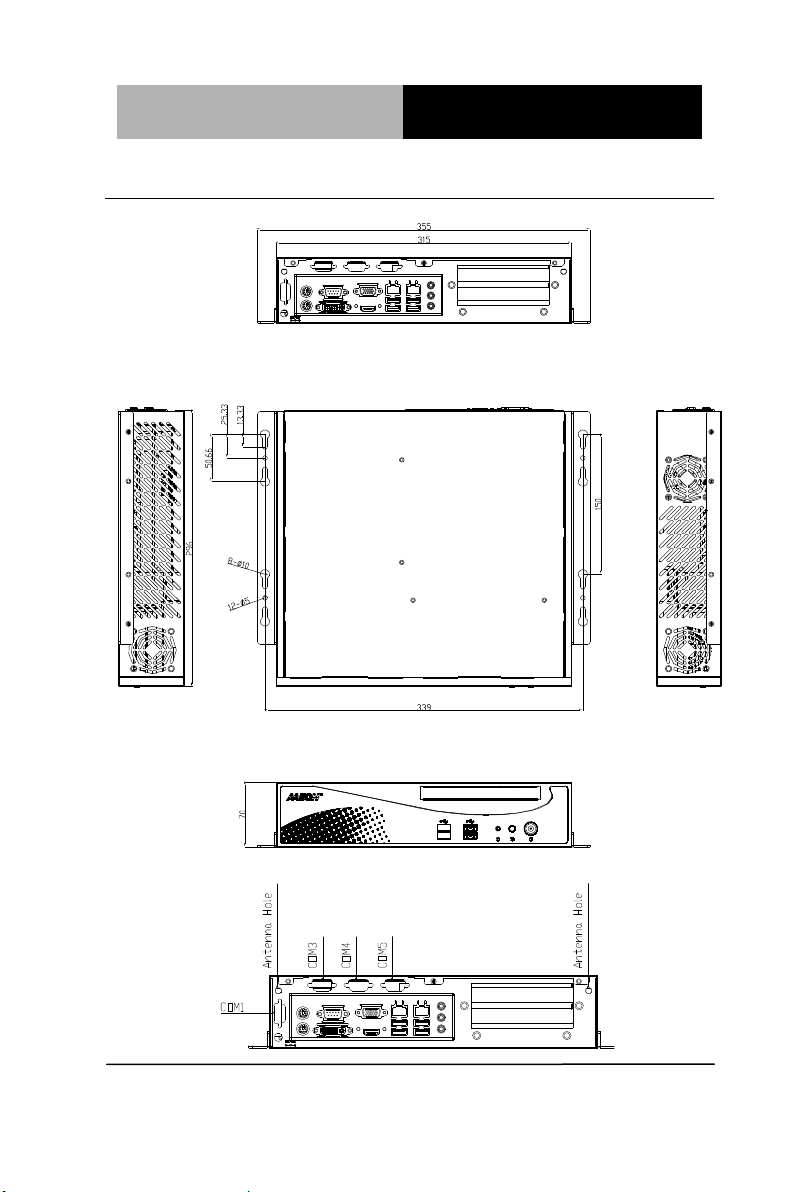
Dimension: 315mm(W) x 70mm(H) x 300mm(D)
Chapter 1 General Information 1- 3
Page 14

Advanced System
Controller
A I S - E1- H 6 1 A
CPU
Socket LGA 1155 2nd Generation
Intel® Core™ i7 / i5 / Celeron®
processors up to 35W
Chipset
Intel® H61
System Memory
204-pin Dual Channel DDR3
1066/1333 MHz SODIMM x2, up
to 16GB
Display
Interface
VGA
DB-15 x 1
DVI
DVI-D x 1
Others
HDMI x 1
Storage
Device
SSD
CF-SATA x 1
HDD
2.5” SATA HDD bay x 2 (optional
3.5” HDD x 1 + 2.5”HDD/SSD x 1)
Optical
ROM
Up to slim ODD x 1
Network
LAN
Gigabit Ethernet
Wireless
-
Front I/O
USB Host
USB2.0 x 2
Others
Power Switch x 1
Rear I/O
USB Host
USB2.0 x 4 (up to 6 x USB2.0 via
expansion slot )
LAN
RJ-45 x 2
Serial Port
RS-232/422/485 x 1 supports
1.3 Specifications
Chapter 1 General Information 1- 4
Page 15

Advanced System
Controller
A I S - E1- H 6 1 A
5/12V, optional RS-232 x 5
Audio
Mic-in, Line-in, Line-out
KB/MS
KB/MS x 1
Others
Power input x 1
Expansion
Mini Card
-
Others
PCI-Express [x4] x 1, Mini-PCIe,
CF-SATA x 1, Antenna hole x 2
Indicator
Front
PWR, HDD
Power Requirement
100~240V AC to DC 12V power
adapter
System Cooling
CPU cooler x 1
System Cooler x 1
Mounting
Wallmount
Operating Temperature
32°F ~ 113°F (0°C ~ 45°C)
Storage Temperature
-4°F ~ 140°F (-20°C ~ 60°C)
Storage Humidity
10~80%, non-condensing
Anti-Vibration
0.5g rms / 5 ~ 500Hz / operation –
HDD
Anti-Shock
15 G peak acceleration (11 msec.
duration) – HDD
Certification
EMC
CE/ FCC class A
Dimension (W x H x D)
12.4" x 2.76" x 11.81" (315mm x
70mm x 300mm)
Weight
13.84 lb (6.3 Kg)
Chapter 1 General Information 1- 5
Page 16

Advanced System
Controller
A I S - E1- H 6 1 A
OS Support
Windows® XP Pro, Windows® 7,
Windows® 8, Linux Kernal 2.6.x
Chapter 1 General Information 1- 6
Page 17

Advanced System
Controller
A I S - E1- H 6 1 A
Chapter
2
Hardware
Installation
Chapter 2 Hardware Installation 2-1
Page 18
Advanced System
Controller
A I S - E1- H 6 1 A
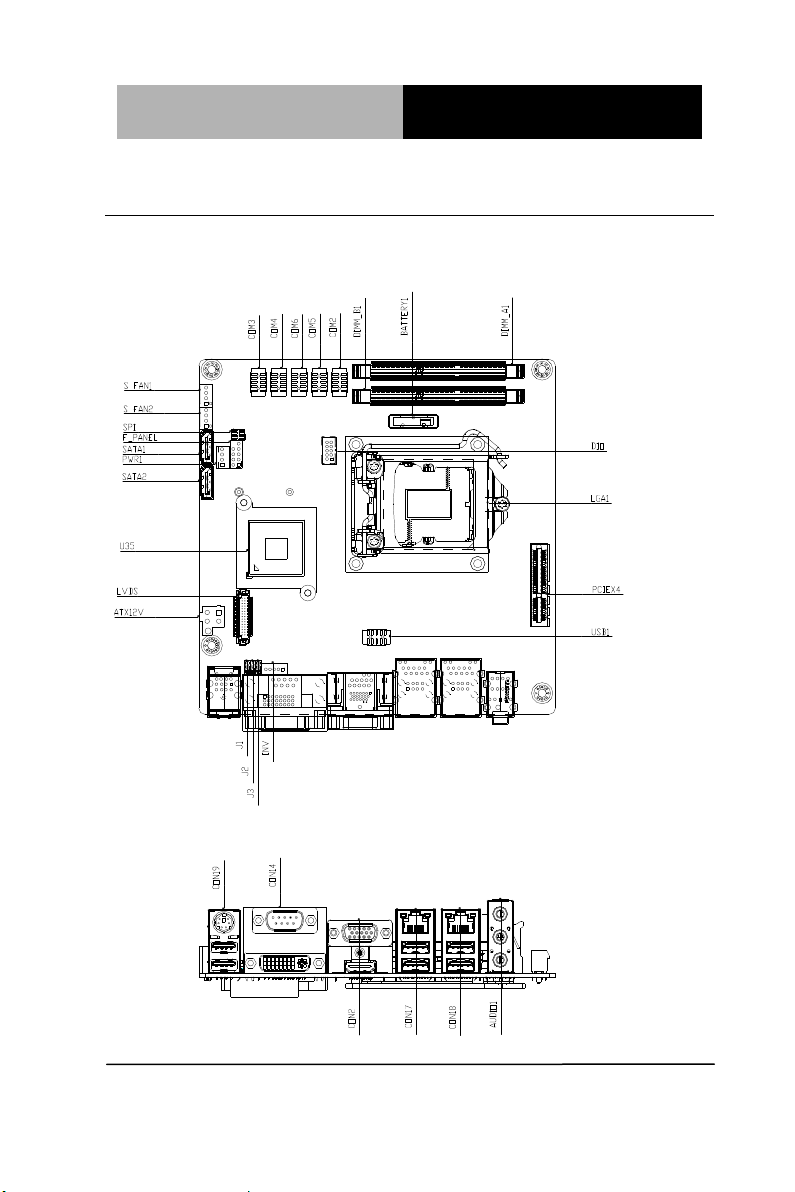
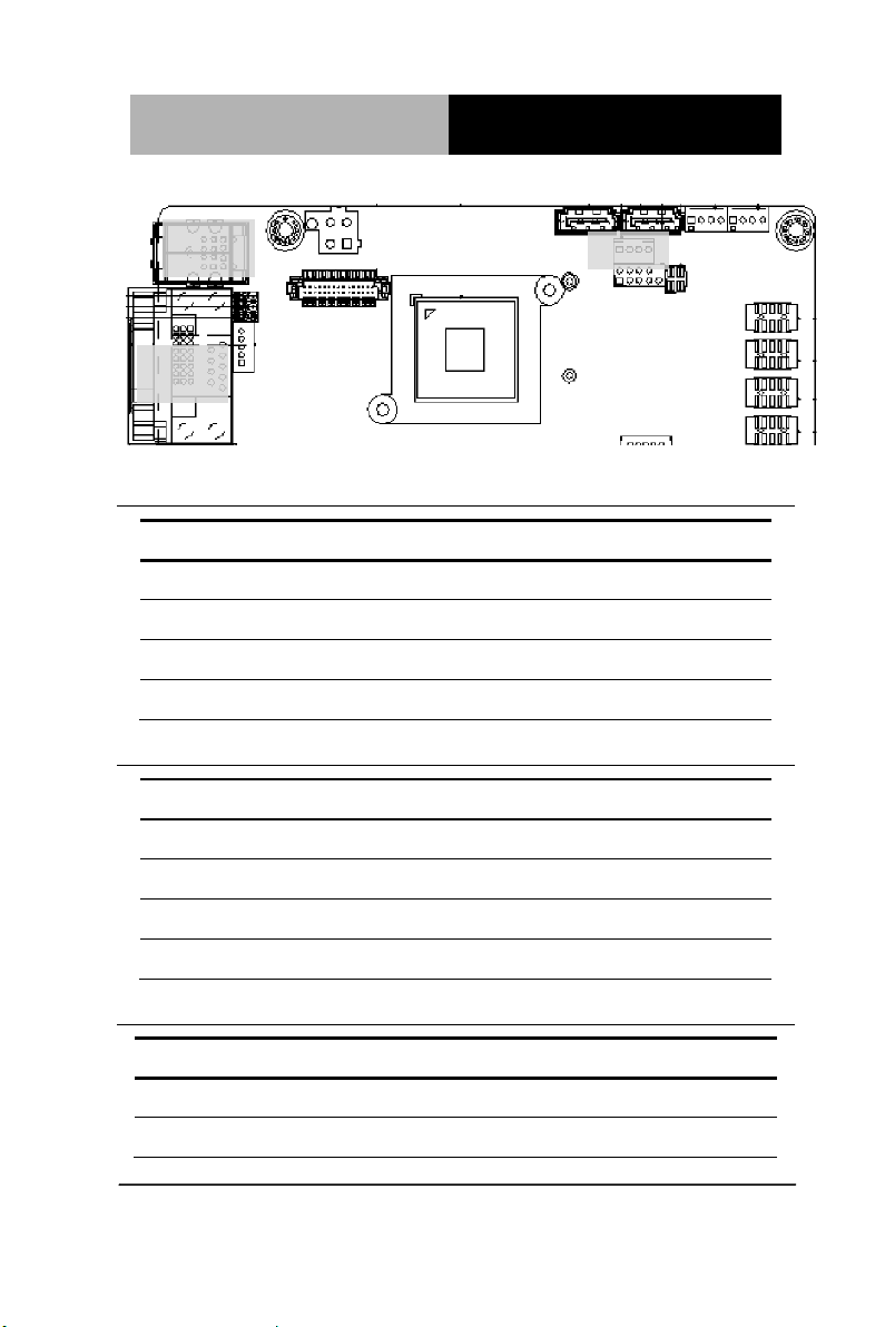
2.1 Location of Connectors (Main Board)
Component Side
Chapter 2 Hardware Installation 2-2
Page 19
Advanced System
Controller
A I S - E1- H 6 1 A
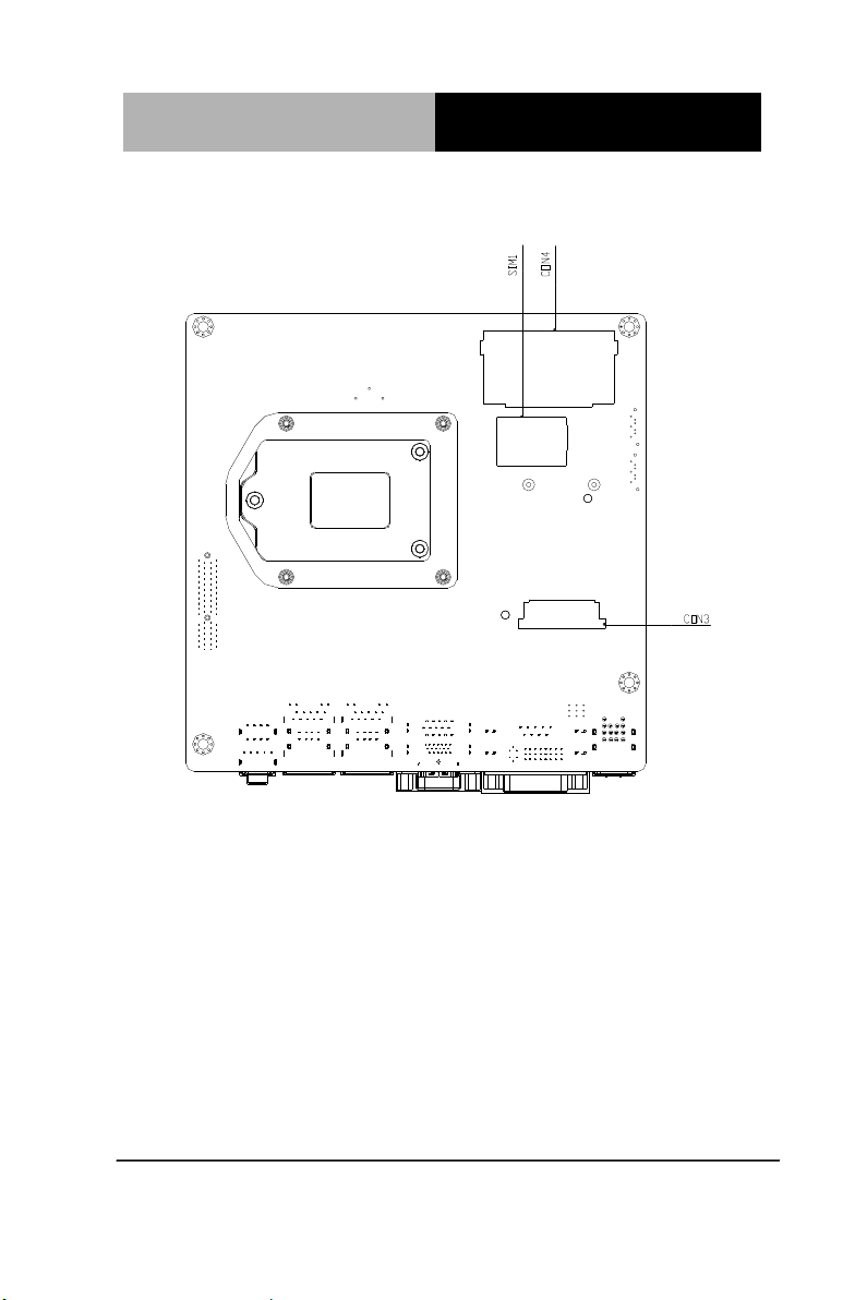
Solder Side
Chapter 2 Hardware Installation 2-3
Page 20
Advanced System
Controller
A I S - E1- H 6 1 A
2.2 Mechanical Drawing of AIS-E1-H61A
I/O Ports
Chapter 2 Hardware Installation 2-4
Page 21

Advanced System
Controller
A I S - E1- H 6 1 A
Label
Function
CLRTC1
Clear CMOS
J1
LVDS Panel Voltage Selection
J2
Inverter Voltage Selection
J3
Mode Selection for Back Light Control of Inverter
J4
AT/ATX mode Selection
J5
COM1 Ring/+5V/+12V Selection
Label
Function
ATX12V
ATX 4P Power Connector
AUDIO1
Audio jack Connector
BATTERY1
RTC - Coin Battery Holder
COM2
COM2 Connector
COM3
COM3 Connector
COM4
COM4 Connector
COM5
COM5 Connector
COM6
COM6 Connector
2.3 List of Jumpers
The board has a number of jumpers that allow you to configure your
system to suit your application.
The table below shows the function of each of the board's jumpers:
2.4 List of Connectors
The board has a number of connectors that allow you to configure
your system to suit your application.
The table below shows the function of each of the board's
connectors:
Chapter 2 Hardware Installation 2-5
Page 22

Advanced System
Controller
A I S - E1- H 6 1 A
CON14
COM1 & DVI-D Connector
CON17
LAN1 and USB1/2 Connector
CON18
LAN2 and USB3/4 Connector
CON19
PS/2 KB&MS and USB5/6 Connector
CON2
D-Sub15_VGA Connector with HDMI
Connector
CON3
mini PCI-E Slot
CON4
Compact Flash Slot
DEBUG
Debug Connector
DIMM_A1
DIMM1 Slot
DIMM_B1
DIMM2 Slot
DIO
Digital I/O Connector
F_PANEL
Front Panel Connector
INV
Inverter Connector
LGA1
CPU Socket - LGA-1155P
LVDS
LVDS Panel Signal Connector
PCIEX4
PCI Express x4 Slot
PWR1
SATA Power Connector
S_FAN1
System FAN Connector
S_FAN2
System FAN Connector
SATA1
SATA II Connector
SATA2
SATA II Connector
SIM1
SIM Card Socket
SPI
BIOS Programmable Connector
USB1
Int. USB 2.0 Connector
Chapter 2 Hardware Installation 2-6
Page 23
Advanced System
Controller
A I S - E1- H 6 1 A
1
2
3
Open Closed Closed 2-3
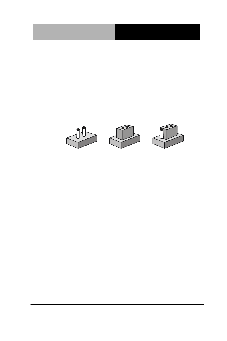
2.5 Setting Jumpers
You configure your card to match the needs of your application by
setting jumpers. A jumper is the simplest kind of electric switch. It
consists of two metal pins and a small metal clip (often protected by
a plastic cover) that slides over the pins to connect them. To “close”
a jumper you connect the pins with the clip.
To “open” a jumper you remove the clip. Sometimes a jumper will
have three pins, labeled 1, 2 and 3. In this case you would connect
either pins 1 and 2 or 2 and 3.
A pair of needle-nose pliers may be helpful when working with
jumpers.
If you have any doubts about the best hardware configuration for
your application, contact your local distributor or sales
representative before you make any change.
Generally, you simply need a standard cable to make most
connections.
Chapter 2 Hardware Installation 2-7
Page 24

Advanced System
Controller
A I S - E1- H 6 1 A
CLRTC1
Function
1-2
Protected (Default)
2-3
Clear
J1
Function
1-2
+5V
2-3
+3.3V (Default)
J2
Function
1-2
+12V
2-3
+5V (Default)
J3
Function
1-2
DC Voltage Control (Default)
2-3
PWM Control
J4
Function
1-2
AT Mode (Default)
Empty
ATX Mode
2.6 Clear CMOS (CLRTC1)
2.7 LVDS Panel Voltage Selection (J1)
2.8 Inverter Voltage Selection (J2)
2.9 Mode Selection for Back Light Control of Inverter (J3)
2.10 AT/ATX Mode Selection (J4)
Chapter 2 Hardware Installation 2-8
Page 25

Advanced System
Controller
A I S - E1- H 6 1 A
J5
Function
1-2
+12V
3-4
+5V
5-6
Ring (Default)
Pin
Signal
Pin
Signal
1
DCD
2
RXD
3
TXD
4
DTR
5
GND
6
DSR
7
RTS
8
CTS
9
RI
10
(NC)
Pin
Signal
Pin
Signal
1
GND
2
USB2_DP1
3
USB2_DN1
4
+5V 5 GND
6
USB2_DP2
7
USB2_DN2
8
+5V 9 GND
10
KB_DATA
11
MS_DATA
12
+5V
13
KB_CLK
14
MS_CLK
15
GND
16
GND
17
GND
18
GND
2.11 COM1 Ring/+5V/+12V Selection (J5)
2.12 Internal COM Serial Port Connector (COM2 ~ COM6)
2.13 PS/2 Keyboard/Mouse Connector with Dock USB 2.0
Connector (CON19)
Chapter 2 Hardware Installation 2-9
Page 26

Advanced System
Controller
A I S - E1- H 6 1 A
Pin
Signal
Pin
Signal
1
+5V 2 USB2_DN2
3
USB2_DP2
4
GND
5
+5V 6 USB2_DN1
7
USB2_DP1
8
GND
9
LAN_CTR
10
LAN_MDI_DP0
11
LAN_MDI_DN0
12
LAN_MDI_DP1
13
LAN_MDI_DN1
14
LAN_MDI_DP2
15
LAN_MDI_DN2
16
LAN_MDI_DP3
17
LAN_MDI_DN3
18
GND
19
LAN_LED_ACT
20
LAN_LED_ACT#
21
LAN_LED_LINK100#
22
LAN_LED_LINK1000#
23
GND
24
GND
25
GND
26
GND
27
GND
28
GND
29
GND
30
GND
Pin
Signal
Pin
Signal
1
DIO_I#1 (DIO_P#1)
2
DIO_I#2 (DIO_P#2)
3
DIO_I#3 (DIO_P#3)
4
DIO_I#4 (DIO_P#4)
5
DIO_O#1 (DIO_P#5)
6
DIO_O#2 (DIO_P#6)
7
DIO_O#3 (DIO_P#7)
8
DIO_O#4 (DIO_P#8)
9
+5V
10
GND
2.14 1000Base-T Ethernet Connector with Dock USB 2.0
Connector (CON17/CON18)
2.15 Digital I/O Connector (DIO)
Chapter 2 Hardware Installation 2-10
Page 27

Advanced System
Controller
A I S - E1- H 6 1 A
Pin
Signal
1
LPC_AD0
2
LPC_AD1
3
LPC_AD2
4
LPC_AD3
5
+3.3V
6
LPC_FRAME#
7
PLTRST#
8
GND
9
CLK_33M_LPC
10
LPC_DRQ#0
11
LPC_DRQ#1
12
SERIRQ#
Pin
Signal
Pin
Signal
1
HDLED+
2
PLED+
3
HDLED-
4
PLED-
5
GND
6
PANSWH#
7
HWRST#
8
GND
9
(NC)
10
(kill pin)
Pin
Signal
1
Inverter VCC
2.16 Debug Connector (DEBUG)
2.17 Front Panel Connector (F_PANEL)
2.18 Inverter Connector (INV)
Chapter 2 Hardware Installation 2-11
Page 28

Advanced System
Controller
A I S - E1- H 6 1 A
3
Back Light Control
5
GND
7
GND
9
Back Light Enable
Pin
Signal
Pin
Signal
1
LVDS1_CLK-
2
LVDS1_CLK+
3
LVDS VCC
4
GND
5
LVDS1_D3-
6
LVDS1_D3+
7
LVDS1_D2-
8
LVDS1_D2+
9
LVDS1_D1-
10
LVDS1_D1+
11
LVDS1_D0-
12
LVDS1_D0+
13
EDID_Data
14
EDID_Clk
15
LVDS0_D3-
16
LVDS0_D3+
17
LVDS0_D2-
18
LVDS0_D2+
19
LVDS0_D1-
20
LVDS0_D1+
21
LVDS0_D0-
22
LVDS0_D0+
23
LVDS VCC
24
GND
25
LVDS0_CLK-
26
LVDS0_CLK+
27
LVDS VCC
28
GND
29
LVDS Panel Enable
30
Backlight Control for DC mode
2.19 LVDS Panel Signal Connector (LVDS)
NOTE: LVDS connector Vendor: PINREX; Model: 712-76-30GWR8. Please
refer the drawing below, notice the location of PIN1, PIN2, PIN29 and
PIN30. KB&MS
Chapter 2 Hardware Installation 2-12
Page 29
Advanced System
Controller
A I S - E1- H 6 1 A
Pin
Signal
1
+5V
2
GND
3
GND
4
+12V
Pin
Signal
1
PWM
2
SENSE
3
VCC
4
GND
4BPin
25BSignal
Pin
5BSignal
1
+V3.3SPI
2
GND
3
SPI_CS#
4
SPI_CLK
1
29 2 30
SATA
KB&MS
USB
COM
DVI-D
2.20 SATA Power Connector (PWR1)
2.21 FAN Connector (S_FAN1/S_FAN2)
2.22 BIOS Programmable Connector (SPI)
Chapter 2 Hardware Installation 2-13
Page 30
Advanced System
Controller
A I S - E1- H 6 1 A
5
SPI_MISO
6
SPI_MOSI
7
(NC)
8
(NC)
Pin
Signal
Pin
Signal
1
+5V 2 GND
3
USB2_DN1
4
GND
5
USB2_DP1
6
USB2_DP2
7
GND
8
USB2_DN2
9
GND
10
+5V
2.23 Internal USB 2.0 Connector (USB1)
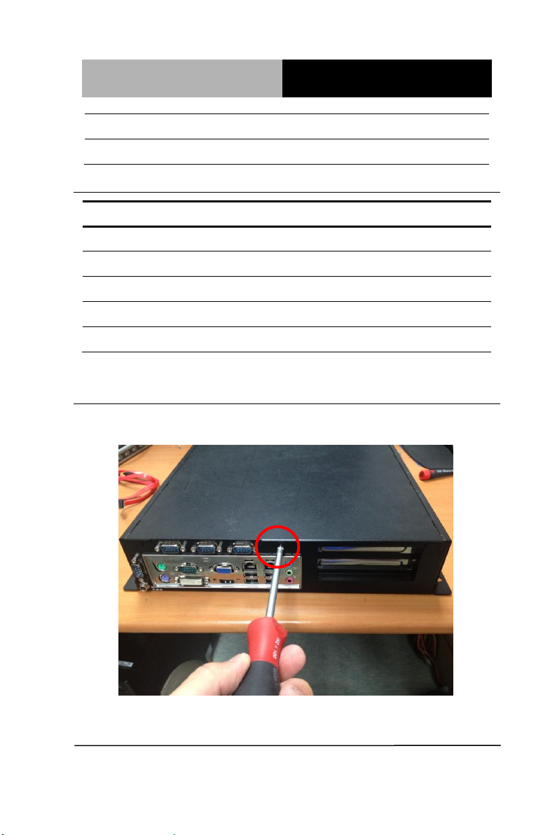
2.24 Installing the Hard Disk Drive
Step 1: Unfasten the screw of the AIS-E1-H61A
Chapter 2 Hardware Installation 2-14
Page 31

Advanced System
Controller
A I S - E1- H 6 1 A
Step 2: Open the upper cover of the AIS-E1-H61A
Step 3: Get the HDD Bracket and fasten the four screws with the
HDD
Chapter 2 Hardware Installation 2-15
Page 32

Advanced System
Controller
A I S - E1- H 6 1 A
Step 4: Put the HDD and bracket back to the chassis by sliding the
HDD bracket and lock to the position.
Step 5: Fasten the screw to finish installing the HDD
Chapter 2 Hardware Installation 2-16
Page 33

Advanced System
Controller
A I S - E1- H 6 1 A
2.25 Installing Three 2.5” Hard Disk Drives
If you have three HDD to install, please refer to the installation
below.
Step 1: Unfasten the screw of the AIS-E1-H61A
Step 2: Open the upper cover of the AIS-E1-H61A
Chapter 2 Hardware Installation 2-17
Page 34

Advanced System
Controller
A I S - E1- H 6 1 A
Step 3: Put the blue rubber damper to the 3-layer HDD bracket and
move the damper to the smaller fillister (you have to put 12 blue
rubber dampers if you have three HDD to install)
Chapter 2 Hardware Installation 2-18
Page 35

Advanced System
Controller
A I S - E1- H 6 1 A
Step 4: Get the four screws ready and pierce to the dampers and
lock the HDD (12 screws for three HDD installations)
Chapter 2 Hardware Installation 2-19
Page 36

Advanced System
Controller
A I S - E1- H 6 1 A
3-layer
HDD
bracket
fillister
fillister
Step 5: Make sure that the fillisters of the 3-layer HDD bracket has
been latched to I-shape nails (blue circles)
Chapter 2 Hardware Installation 2-20
Page 37

Advanced System
Controller
A I S - E1- H 6 1 A
Step 6: Fasten the screw to lock the HDD bracket with the Chassis
and you’ve done installing the three HDD
Chapter 2 Hardware Installation 2-21
Page 38

Advanced System
Controller
A I S - E1- H 6 1 A
Chapter
3
AMI
BIOS Setup
Chapter 3 AMI BIOS Setup 3-1
Page 39

Advanced System
Controller
A I S - E1- H 6 1 A
3.1 System Test and Initialization
These routines test and initialize board hardware. If the routines
encounter an error during the tests, you will either hear a few short
beeps or see an error message on the screen. There are two kinds
of errors: fatal and non-fatal. The system can usually continue the
boot up sequence with non-fatal errors.
System configuration verification
These routines check the current system configuration against the
values stored in the CMOS memory. If they do not match, the
program outputs an error message. You will then need to run the
BIOS setup program to set the configuration information in memory.
There are three situations in which you will need to change the
CMOS settings:
1. You are starting your system for the first time
2. You have changed the hardware attached to your system
3. The CMOS memory has lost power and the configuration
information has been erased.
The AIS-E1-H61A CMOS memory has an integral lithium battery
backup for data retention. However, you will need to replace the
complete unit when it finally runs down.
Chapter 3 AMI BIOS Setup 3-2
Page 40

Advanced System
Controller
A I S - E1- H 6 1 A
3.2 AMI BIOS Setup
AMI BIOS ROM has a built-in Setup program that allows users to
modify the basic system configuration. This type of information is
stored in battery-backed CMOS RAM so that it retains the Setup
information when the power is turned off.
Entering Setup
Power on the computer and press <Del> or <F2> immediately. This
will allow you to enter Setup.
Main
Set the date, use tab to switch between date elements.
Advanced
Enable disable boot option for legacy network devices.
Chipset
Host bridge parameters.
Boot
Enables/disable quiet boot option.
Security
Set setup administrator password.
Save&Exit
Exit system setup after saving the changes.
Chapter 3 AMI BIOS Setup 3-3
Page 41

Advanced System
Controller
A I S - E1- H 6 1 A
Setup Menu
Setup submenu: Main
Chapter 3 AMI BIOS Setup 3-4
Page 42

Advanced System
Controller
A I S - E1- H 6 1 A
Setup submenu: Advanced
Chapter 3 AMI BIOS Setup 3-5
Page 43

Advanced System
Controller
A I S - E1- H 6 1 A
Suspend mode
S1 (CPU Stop Clock)
S3 (Suspend to RAM)
Optimal Default, Failsafe Default
Select the ACPI state used for System Suspend
ACPI Settings
Options summary :
Chapter 3 AMI BIOS Setup 3-6
Page 44

Advanced System
Controller
A I S - E1- H 6 1 A
Security Device
Support
Disabled
Optimal Default, Failsafe
Default
Enabled
En/Disable TPM support.
TPM State
Disabled
Optimal Default, Failsafe
Default
Enabled
En/Disable TPM State.
Trusted Computing
Options summary:
Chapter 3 AMI BIOS Setup 3-7
Page 45

Advanced System
Controller
A I S - E1- H 6 1 A
Pending
Operation
None
Optimal Default, Failsafe
Default
Enable Take
Ownership
Disable Take
Ownership
TPM Clear
Select one-time TPM operation. Item value returns to „None‟ after next
POST.
Chapter 3 AMI BIOS Setup 3-8
Page 46

Advanced System
Controller
A I S - E1- H 6 1 A
Wake system with
Fixed Time
Disabled
Optimal Default,
Failsafe Default
Enabled
En/Disabled system wake on alarm event. When enabled, System will wake
on the hr::min::sec specified.
Wake system with
Dyamic Time
Disabled
Optimal Default,
Failsafe Default
Enabled
S5 RTC Wake Settings
Options summary :
Chapter 3 AMI BIOS Setup 3-9
Page 47

Advanced System
Controller
A I S - E1- H 6 1 A
En/Disabled system wake on alarm event. When enabled, System will
wake on the current time + Increase minute(s).
Chapter 3 AMI BIOS Setup 3-10
Page 48

Advanced System
Controller
A I S - E1- H 6 1 A
Hyper-Threading
Disabled
Enabled
Optimal Default, Failsafe Default
En/Disable CPU Hyper-Threading function
Intel
Virtualization
Technology
Disabled
Optimal Default, Failsafe Default
Enabled
En/Disable Intel VT-x function
CPU Configuration
Options summary :
Chapter 3 AMI BIOS Setup 3-11
Page 49

Advanced System
Controller
A I S - E1- H 6 1 A
SATA Configuration
Chapter 3 AMI BIOS Setup 3-12
Page 50

Advanced System
Controller
A I S - E1- H 6 1 A
SATA#1 IDE
Configuration
Disabled
Default
Enabled
Compatible: Configure SATA controller #1 as a legacy compatible
controller.
Enhanced: Configure SATA controller #1 as a Intel enhanced controller.
SATA Mode
IDE
Default
AHCI
IDE: Configure SATA controllers as legacy IDE
AHCI: Configure SATA controllers to operate in AHCI mode
SATA Configuration (AHCI)
Options summary :
Chapter 3 AMI BIOS Setup 3-13
Page 51

Advanced System
Controller
A I S - E1- H 6 1 A
Hot Plug
Disabled
Optimal Default, Failsafe
Default
Enabled
En/Disable Hot Plug feature.
Chapter 3 AMI BIOS Setup 3-14
Page 52

Advanced System
Controller
A I S - E1- H 6 1 A
Legacy USB Support
Enabled
Optimal Default, Failsafe
Default
Disabled
Auto
Enables BIOS Support for Legacy USB Support. When enabled, USB
can be functional in legacy environment like DOS.
AUTO option disables legacy support if no USB devices are connected
Device Name
(Emulation Type)
Auto
Optimal Default, Failsafe
Default
USB Configuration
Options summary:
Chapter 3 AMI BIOS Setup 3-15
Page 53

Advanced System
Controller
A I S - E1- H 6 1 A
Floppy
Forced FDD
Hard Disk
CDROM
If Auto. USB devices less than 530MB will be emulated as Floppy and
remaining as Floppy and remaining as hard drive. Forced FDD option
can be used to force a HDD formatted drive to boot as FDD(Ex. ZIP
drive)
F81866 Supoer IO Configuration
Chapter 3 AMI BIOS Setup 3-16
Page 54

Advanced System
Controller
A I S - E1- H 6 1 A
F81866 ERP Function
Disabled
Default
Enabled
Enable or Disable ERP function.
Serial Port
Disabled
Enabled
Default
Allows BIOS to En/Disable correspond serial port.
Device Mode
RS232
Default
Serial Port Configuration
Options summary :
Chapter 3 AMI BIOS Setup 3-17
Page 55

Advanced System
Controller
A I S - E1- H 6 1 A
RS422
RS485
Select working model.
Change Settings
(Serial Port 1)
Auto
Default
IO=3F8h; IRQ=4;
IO=3F8h; IRQ=3,4;
IO=2F8h; IRQ=3,4;
IO=3E8h;
IRQ=10,11;
IO=2E8h;
IRQ=10,11
Allows BIOS to Select Serial Port resource.
Change Settings
(Serial Port 2)
Auto
Default
IO=2F8h; IRQ=3;
IO=3F8h; IRQ=3,4;
IO=2F8h; IRQ=3,4;
IO=3E8h;
IRQ=10,11;
Chapter 3 AMI BIOS Setup 3-18
Page 56

Advanced System
Controller
A I S - E1- H 6 1 A
IO=2E8h;
IRQ=10,11
Allows BIOS to Select Serial Port resource.
Change Settings
(Serial Port 3)
Auto
Default
IO=3E8h;
IRQ=10,11;
IO=2E8h;
IRQ=10,11;
IO=2D0h;
IRQ=10,11;
IO=2D8h;
IRQ=10,11
Allows BIOS to Select Serial Port resource.
Change Settings
(Serial Port 4)
Auto
Default
IO=2E8h;
IRQ=10,11;
IO=3E8h;
IRQ=10,11;
IO=2D0h;
IRQ=10,11;
IO=2D8h;
IRQ=10,11;
Chapter 3 AMI BIOS Setup 3-19
Page 57

Advanced System
Controller
A I S - E1- H 6 1 A
Allows BIOS to Select Serial Port resource.
Change Settings
(Serial Port 5)
Auto
Default
IO=2D0h;
IRQ=10,11;
IO=3E8h;
IRQ=10,11;
IO=2E8h;
IRQ=10,11;
IO=2D8h;
IRQ=10,11
Allows BIOS to Select Serial Port resource.
Chapter 3 AMI BIOS Setup 3-20
Page 58

Advanced System
Controller
A I S - E1- H 6 1 A
On-Module H/W Monitor
Chapter 3 AMI BIOS Setup 3-21
Page 59

Advanced System
Controller
A I S - E1- H 6 1 A
Smart Fan Mode Configuration
Chapter 3 AMI BIOS Setup 3-22
Page 60

Advanced System
Controller
A I S - E1- H 6 1 A
SYS/CPU Smart Fan
Control
Auto by RPM
Default
Auto by Duty-Cycle
Manual by RPM
Manual by Duty-Cycle
Options summary :
Chapter 3 AMI BIOS Setup 3-23
Page 61

Advanced System
Controller
A I S - E1- H 6 1 A
Select CPU Smart FAN mode
Auto by RPM: Automatically controlling the fan to maintain target Fan
Speed.
Auto by Duty-Cycle: Automatically controlling the fan to maintain
target temperature.
Manual by RPM: Manually controlling the fan with a given Fan Speed.
Manual by Duty-Cycle: Manually controlling the fan with a given
control PWM.
Target Temp. Sensor
CPU Temperature
Default
PCH Temperature
Select target temperature source.
Setup submenu: Chipset
Chapter 3 AMI BIOS Setup 3-24
Page 62

Advanced System
Controller
A I S - E1- H 6 1 A
PCH-IO Configuration
Chapter 3 AMI BIOS Setup 3-25
Page 63

Advanced System
Controller
A I S - E1- H 6 1 A
Azalia
Disabled
Enabled
Optimal Default,
Failsafe Default
Enabling/Disabling HD Audio controller.
Azalia internal HDMI Codec
Disabled
Optimal Default,
Failsafe Default
Enabled
Enabling/Disabling internal HDMI codec.
Power Mode
ATX Type
Default
AT Type
Options summary :
Chapter 3 AMI BIOS Setup 3-26
Page 64

Advanced System
Controller
A I S - E1- H 6 1 A
Select power supply mode.
Restore on AC Power Loss
Power Off
Power On
Last State
Default
Select the action system to take when restoring from power loss.
JMB 368 ATA Controller
Disabled
Enabled
Default
En/Disable JMB 368 ATA Controller.
Mini PCI-E Gen Speed
Gen1
Optimal Default,
Failsafe Default
Gen2
Select PCI Express Gen speed.
Resume on Ring
Disabled
Default
Enabled
En/Disabled resuming from RI# signal.
Chapter 3 AMI BIOS Setup 3-27
Page 65

Advanced System
Controller
A I S - E1- H 6 1 A
VT-d
Disabled
Enabled
Default
En/Disable chipset Virtualization Technology function.
PCIE x 4 Gen Speed
Gen1
Optimal Default, Failsafe Default
Gen2
Select PCI Express Gen speed.
System Agent(SA) Configuration
Options summary :
Chapter 3 AMI BIOS Setup 3-28
Page 66

Advanced System
Controller
A I S - E1- H 6 1 A
Primary Display
Auto
Default
IGFX
PEG
Select which of IGFX/PEG Graphics device should be Primary Display.
Internal Graphics
Auto
Default
Disable
Enable
Keep IGD enabled based on the setup options.
GTT Size
1MB
Graphics Configuration
Options summary :
Chapter 3 AMI BIOS Setup 3-29
Page 67

Advanced System
Controller
A I S - E1- H 6 1 A
2MB
Default
Select the GTT Size.
Aperture Size
128MB
256MB
Default
512MB
Select the Aperture Size.
DVMT Pre-Allocated
32M
64M
Default
96M
128M
160M
192M
224M
256M
288M
320M
352M
384M
416M
448M
480M
512M
1024M
Chapter 3 AMI BIOS Setup 3-30
Page 68

Advanced System
Controller
A I S - E1- H 6 1 A
Select DVMT 5.0 Pre-Allocated(Fixed) Graphics Memory size used by
the Internal Graphics Device.
Primary IGFX Boot Display
AUTO
Default
CRT
HDMI
LVDS
DVI
Select the Video Device which will be activated during POST. For
dual-display, select “Auto”. Note: The platform only supports single
display in legacy environment (DOS).
Chapter 3 AMI BIOS Setup 3-31
Page 69

Advanced System
Controller
A I S - E1- H 6 1 A
Bootup NumLock State
On
Default
Off Select the keyboard NumLock state.
Quiet Boot
Disabled
Default
Enabled
En/Disable showing boot logo.
Launch RTL8111E PXE
OpROM
Disabled
Default
Enabled
Enable or Disable Legacy Boot Option for RTL811E.
Setup submenu: Boot
Options summary :
Chapter 3 AMI BIOS Setup 3-32
Page 70

Advanced System
Controller
A I S - E1- H 6 1 A
GateA20 Active
Upon Request
Default
Always
UPON REQUEST – GA20 can be disabled using BIOS services.
ALWAYS – do not allow disabling GA20; this option is useful when any RT
code is executed above 1MB.
Option ROM Messages
Force BIOS
Default
Keep Current
Set display mode for Option ROM.
INT19 Trap Response
Immediate
Default
Postponed
BIOS reaction on INT19 trapping by Option ROM:
IMMEDIATE – execute the trap right away;
POSTPONED – execute the trap during legacy boot.
Chapter 3 AMI BIOS Setup 3-33
Page 71

Advanced System
Controller
A I S - E1- H 6 1 A
Setup submenu: Security
Change User/Supervisor Password
You can install a Supervisor password, and if you install a
supervisor password, you can then install a user password. A user
password does not provide access to many of the features in the
Setup utility.
If you highlight these items and press Enter, a dialog box appears
which lets you enter a password. You can enter no more than six
letters or numbers. Press Enter after you have typed in the
password. A second dialog box asks you to retype the password
for confirmation. Press Enter after you have retyped it correctly.
The password is required at boot time, or when the user enters the
Chapter 3 AMI BIOS Setup 3-34
Page 72

Advanced System
Controller
A I S - E1- H 6 1 A
Setup utility.
Removing the Password
Highlight this item and type in the current password. At the next
dialog box press Enter to disable password protection.
Chapter 3 AMI BIOS Setup 3-35
Page 73

Advanced System
Controller
A I S - E1- H 6 1 A
Setup submenu: Exit
Chapter 3 AMI BIOS Setup 3-36
Page 74

Advanced System
Controller
A I S - E1- H 6 1 A
Chapter
4
0BDriver
Installation
.
Chapter 4 Driver Installation 4 -1
Page 75

Advanced System
Controller
A I S - E1- H 6 1 A
The AIS-E1-H61A comes with an AutoRun DVD-ROM that contains
all drivers and utilities that can help you to install the driver
automatically.
Insert the driver DVD, the driver DVD-title will auto start and show
the installation guide. If not, please follow the sequence below to
install the drivers.
Follow the sequence below to install the drivers:
Step 1 – Install Chipset Driver
Step 2 – Install VGA Driver
Step 3 – Install LAN Driver
Step 4 – Install Audio Driver
Step 5 – Install TPM Driver
Step 6 – Install ME Driver
Step 7 – Install AHCI Driver
Step 8 – Install Serial Port Driver (Optional)
Note: If you got compatible issue for COM port, please find its driver under
STEP 8 folder and then install it by administrative login permission.
Please read instructions below for further detailed installations.
Chapter 4 Driver Installation 4 -2
Page 76

Advanced System
Controller
A I S - E1- H 6 1 A
4.1 Installation:
Insert the AIS-E1-H61A DVD-ROM into the DVD-ROM drive. And
install the drivers from Step 1 to Step 8 in order.
Step 1 – Install Chipset Driver
1. Click on the Step 1 - INF folder and double click on
the Setup.exe file
2. Follow the instructions that the window shows
3. The system will help you install the driver
automatically
Step 2 – Install VGA Driver
1. Click on the Step 2 - VGA folder and select the OS
folder your system is
2. Double click on the setup.exe file located in each OS
folder
3. Follow the instructions that the window shows
4. The system will help you install the driver
Note: If the OS is Windows® XP, you have to install the driver of dotNet
Framework first. Simply click on dotnetfx35.exe
Step 3 –Install LAN Driver
1. Click on the Step 3 - LAN folder and select the OS
2. Double click on the Setup.exe file located in each
automatically
folder your system is
OS folder
Chapter 4 Driver Installation 4 -3
Page 77

Advanced System
Controller
A I S - E1- H 6 1 A
3. Follow the instructions that the window shows
4. The system will help you install the driver
automatically
Step 4 –Install Audio Driver
1. Click on the Step 4 - AUDIO folder and select the OS
folder your system is
2. Double click on the Setup.exe located in each OS
folder
3. Follow the instructions that the window shows
4. The system will help you install the driver
automatically
Step 5 – Install TPM Driver
1. Click on the Step 5 - TPM folder and select the folder
of OS folder your system is
2. Double click on the Setup.exe located in each OS
folder
3. Follow the instructions that the window shows
4. The system will help you install the driver
Step 6 – Install ME Driver
1. Click on the Step 6 - ME folder and select the folder of
2. Double click on the Setup.exe located in each OS
3. Follow the instructions that the window shows
4. The system will help you install the driver
Chapter 4 Driver Installation 4 -4
automatically
OS folder your system is
folder
Page 78

Advanced System
Controller
A I S - E1- H 6 1 A
automatically
Step 7 – Install AHCI Driver
Please refer to the Appendix C AHCI Setting
Step 8 –Install Serial Port Driver (Optional)
For Windows® XP 32-bit
1. Click on the Step 8 - Serial Port Driver (Optional)
folder and select the folder of WINXP_32
2. Double click on the patch.bat
3. Follow the instructions that the window shows
4. The system will help you install the driver
automatically
Chapter 4 Driver Installation 4 -5
Page 79

Advanced System
Controller
A I S - E1- H 6 1 A
For Windows® 7 32-bit/ 64-bit
1. Create a password for Administrator account.
2. Change User Account Control Settings to [Never notify]
Chapter 4 Driver Installation 4 -6
Page 80

Advanced System
Controller
A I S - E1- H 6 1 A
3. Reboot and Administrator login.
4. To run patch.bat with [Run as administrator].
Chapter 4 Driver Installation 4 -7
Page 81

Advanced System
Controller
A I S - E1- H 6 1 A
You also can install the serial port driver for Windows 7 by the
Installation Procedure 2 below:
-Win7 32-bit
Copy the Driver CD\Serial Port Driver (Optional) \WIN7_32\
win7_X86 \serial.sys to C:\WINDOWS\system32\drivers\
-Win7 64-bit
Copy the Driver CD\Serial Port Driver (Optional) \WIN7_64
\win7_amd64\serial.sys to C:\WINDOWS\system32\drivers\
Chapter 4 Driver Installation 4 -8
Page 82

Advanced System
Controller
A I S - E1- H 6 1 A
Chapter 4 Driver Installation 4 -9
Page 83

Advanced System
Controller
A I S - E1- H 6 1 A
Appendix
A
Programming the
Watchdog Timer
Appendix A Programming the Watchdog Timer A-1
Page 84

Advanced System
Controller
A I S - E1- H 6 1 A
Table 1 : SuperIO relative register table
Default Value
Note
Index
0x2E(Note1)
SIO MB PnP Mode Index Register
0x2E or 0x4E
Data
0x2F(Note2)
SIO MB PnP Mode Data Register
0x2F or 0x4F
Table 2 : Watchdog relative register table
LDN
Register
BitNum
Value
Note
Timer Counter
0x07(Note3)
0xF6(Note4)
(Note24)
Time of watchdog timer
(0~255)
This register is byte
access
Counting Unit
0x07(Note5)
0xF5(Note6)
3(Note7)
0(Note8)
Select time unit.
0: second
1: minute
Watchdog
Enable
0x07(Note9)
0xF5(Note10)
5(Note11)
1(Note12)
0: Disable
1: Enable
Timeout
Status
0x07(Note13)
0xF5(Note14)
6(Note15)
1
1: Clear timeout status
Output Mode
0x07(Note16)
0xF5(Note17)
4(Note18)
1(Note19)
Select WDTRST# output
mode
0: level
1: pulse
WDTRST
output
0x07(Note20)
0xFA(Note21)
0(Note22)
1(Note23)
Enable/Disable
time out output via
WDTRST#
0: Disable
1: Enable
A.1 Watchdog Timer Initial Program
************************************************************************************
// SuperIO relative definition (Please reference to Table 1)
#define byte SIOIndex //This parameter is represented from Note1
#define byte SIOData //This parameter is represented from Note2
Appendix A Programming the Watchdog Timer A-2
Page 85

Advanced System
Controller
A I S - E1- H 6 1 A
#define void IOWriteByte(byte IOPort, byte Value);
#define byte IOReadByte(byte IOPort);
// Watch Dog relative definition (Please reference to Table 2)
#define byte TimerLDN //This parameter is represented from Note3
#define byte TimerReg //This parameter is represented from Note4
#define byte TimerVal // This parameter is represented from Note24
#define byte UnitLDN //This parameter is represented from Note5
#define byte UnitReg //This parameter is represented from Note6
#define byte UnitBit //This parameter is represented from Note7
#define byte UnitVal //This parameter is represented from Note8
#define byte EnableLDN //This parameter is represented from Note9
#define byte EnableReg //This parameter is represented from Note10
#define byte EnableBit //This parameter is represented from Note11
#define byte EnableVal //This parameter is represented from Note12
#define byte StatusLDN // This parameter is represented from Note13
#define byte StatusReg // This parameter is represented from Note14
#define byte StatusBit // This parameter is represented from Note15
#define byte ModeLDN // This parameter is represented from Note16
#define byte ModeReg // This parameter is represented from Note17
#define byte ModeBit // This parameter is represented from Note18
#define byte ModeVal // This parameter is represented from Note19
#define byte WDTRstLDN // This parameter is represented from Note20
#define byte WDTRstReg // This parameter is represented from Note21
#define byte WDTRstBit // This parameter is represented from Note22
#define byte WDTRstVal // This parameter is represented from Note23
************************************************************************************
Appendix A Programming the Watchdog Timer A-3
Page 86

Advanced System
Controller
A I S - E1- H 6 1 A
************************************************************************************
VOID Main(){
// Procedure : AaeonWDTConfig
// (byte)Timer : Time of WDT timer.(0x00~0xFF)
// (boolean)Unit : Select time unit(0: second, 1: minute).
AaeonWDTConfig();
// Procedure : AaeonWDTEnable
// This procudure will enable the WDT counting.
AaeonWDTEnable();
}
************************************************************************************
Appendix A Programming the Watchdog Timer A-4
Page 87

Advanced System
Controller
A I S - E1- H 6 1 A
************************************************************************************
// Procedure : AaeonWDTEnable
VOID AaeonWDTEnable (){
WDTEnableDisable(EnableLDN, EnableReg, EnableBit, 1);
}
// Procedure : AaeonWDTConfig
VOID AaeonWDTConfig (){
// Disable WDT counting
WDTEnableDisable(EnableLDN, EnableReg, EnableBit, 0);
// Clear Watchdog T imeout Status
WDTClearTimeoutStatus();
// WDT relative parameter setting
WDTParameterSetting();
}
VOID WDTEnableDisable(byte LDN, byte Register, byte BitNum, byte Value){
SIOBitSet(LDN, Register, BitNum, Value);
}
VOID WDTParameterSetting(){
// Watchdog Timer counter setting
SIOByteSet(TimerLDN, TimerReg, TimerVal);
// WDT counting unit setting
SIOBitSet(UnitLDN, UnitReg, UnitBit, UnitVal);
// WDT output mode setting, level / pulse
SIOBitSet(ModeLDN, ModeReg, ModeBit, ModeVal);
// Watchdog timeout output via WDTRST#
SIOBitSet(WDTRstLDN, WDTRstReg, WDTRstBit, WDTRstVal);
}
VOID WDTClearTimeoutStatus(){
SIOBitSet(StatusLDN, StatusReg, StatusBit, 1);
}
************************************************************************************
Appendix A Programming the Watchdog Timer A-5
Page 88

Advanced System
Controller
A I S - E1- H 6 1 A
************************************************************************************
VOID SIOEnterMBPnPMode(){
IOWriteByte(SIOIndex, 0x87);
IOWriteByte(SIOIndex, 0x87);
}
VOID SIOExitMBPnPMode(){
IOWriteByte(SIOIndex, 0xAA);
}
VOID SIOSelectLDN(byte LDN){
IOWriteByte(SIOIndex, 0x07); // SIO LDN Register Offset = 0x07
IOWriteByte(SIOData, LDN);
}
VOID SIOBitSet(byte LDN, byte Register, byte BitNum, byte Value){
Byte TmpValue;
SIOEnterMBPnPMode();
SIOSelectLDN(byte LDN);
IOWriteByte(SIOIndex, Register);
TmpValue = IOReadByte(SIOData);
TmpValue &= ~(1 << BitNum);
TmpValue |= (Value << BitNum);
IOWriteByte(SIOData, TmpValue);
SIOExitMBPnPMode();
}
VOID SIOByteSet(byte LDN, byte Register, byte Value){
SIOEnterMBPnPMode();
SIOSelectLDN(LDN);
IOWriteByte(SIOIndex, Register);
IOWriteByte(SIOData, Value);
SIOExitMBPnPMode();
}
************************************************************************************
Appendix A Programming the Watchdog Timer A-6
Page 89

Advanced System
Controller
A I S - E1- H 6 1 A
Appendix
B
I/O Information
Appendix B I/O Information B-1
Page 90

Advanced System
Controller
A I S - E1- H 6 1 A
B.1 I/O Address Map
Appendix B I/O Information B-2
Page 91

Advanced System
Controller
A I S - E1- H 6 1 A
Appendix B I/O Information B-3
Page 92

Advanced System
Controller
A I S - E1- H 6 1 A
B.2 1st MB Memory Address Map
Appendix B I/O Information B-4
Page 93

Advanced System
Controller
A I S - E1- H 6 1 A
B.3 IRQ Mapping Chart
Appendix B I/O Information B-5
Page 94

Advanced System
Controller
A I S - E1- H 6 1 A
Appendix B I/O Information B-6
Page 95

Advanced System
Controller
A I S - E1- H 6 1 A
B.4 DMA Channel Assignments
Appendix B I/O Information B-7
Page 96

Advanced System
Controller
A I S - E1- H 6 1 A
Appendix
C
AHCI Setting
Appendix C AHCI Setting C-1
Page 97

Advanced System
Controller
A I S - E1- H 6 1 A
C.1 Setting AHCI
OS installation to setup AHCI Mode
Step 1: Copy the files below from “Driver CD -> Step 7 - AHCI -> Floppy -
x86” to Disk
Step 2: Connect the USB Floppy (disk with AHCI files) to the AIS-E1-H61A
Step 3: The setting procedures “ In BIOS Setup Menu”
A: Advanced -> SATA Configuration -> SATA Configuration -> SATA
Mode -> AHCI Mode
Appendix C AHCI Setting C-2
Page 98

Advanced System
Controller
A I S - E1- H 6 1 A
Step 4: The setting procedures “In BIOS Setup Menu”
B: Boot -> Boot Option #1 -> DVD-ROM Type
Step 5: The setting procedures “In BIOS Setup Menu”
C: Save & Exit -> Save Changes and Exit
Appendix C AHCI Setting C-3
Page 99

Advanced System
Controller
A I S - E1- H 6 1 A
Step 6: Setup OS
Step 7: Press “F6”
Appendix C AHCI Setting C-4
Page 100

Advanced System
Controller
A I S - E1- H 6 1 A
Step 8: Choose “S”
Step 9: Choose “Intel(R) 5 Series 6 Port SATA AHCI Controller”
Appendix C AHCI Setting C-5
 Loading...