

Page 1

Advanced System
Controller
AIS-E1
AIS-E1
Advanced System Controller
3.5” HDD x 1, 2.5” HDD/SSD x 4
Slim ODD x 1
Gigabit Ethernet x 2
COM x 1, USB2.0 x 6
HD Audio Codec
AIS-E1 Manual 1st Ed.
July 2012
Page 2

Advanced System
Controller
AIS-E1
Copyright Notice
This document is copyrighted, 2012. All rights are reserved. The
original manufacturer reserves the right to make improvements to
the products described in this manual at any time without notice.
No part of this manual may be reproduced, copied, translated, or
transmitted in any form or by any means without the prior written
permission of the original manufacturer. Information provided in
this manual is intended to be accurate and reliable. However, the
original manufacturer assumes no responsibility for its use, or for
any infringements upon the rights of third parties that may result
from its use.
The material in this document is for product information only and is
subject to change without notice. While reasonable efforts have
been made in the preparation of this document to assure its
accuracy, AAEON assumes no liabilities resulting from errors or
omissions in this document, or from the use of the information
contained herein.
AAEON reserves the right to make changes in the product design
without notice to its users.
i
Page 3

Advanced System
Controller
AIS-E1
Acknowledgments
All other products’ name or trademarks are properties of their
respective owners.
AMI is a trademark of American Megatrends Inc.
CompactFlash
™ is a trademark of the Compact Flash
Association.
Intel
®
, CoreTM and Celeron® are trademarks of Intel®
Corporation.
Microsoft Windows
®
is a registered trademark of Microsoft Corp.
ITE is a trademark of Integrated Technology Express, Inc.
IBM, PC/AT, PS/2, and VGA are trademarks of International
Business Machines Corporation.
SoundBlaster is a trademark of Creative Labs, Inc.
Please be notified that all other products’ name or trademarks
not be mentioned above are properties of their respective
owners.
ii
Page 4

Advanced System
Controller
AIS-E1
Packing List
Before you begin operating your PC, please make sure that the
following materials are enclosed:
1 9761E10000 Gift Box
1 AIS-E1
1 DVD-ROM for manual (in PDF format) and drivers
If any of these items should be missing or damaged, please contact
your distributor or sales representative immediately.
iii
Page 5

Advanced System
Controller
AIS-E1
Safety & Warranty
1. Read these safety instructions carefully.
2. Keep this user's manual for later reference.
3. Disconnect this equipment from any AC outlet before cleaning. Do
not use liquid or spray detergents for cleaning. Use a damp cl oth.
4. For pluggable equipment, the power outlet must be installed near
the equipment and must be easily accessible.
5. Keep this equipment away from humidity.
6. Put this equipment on a firm surface during installation. Dropping
it or letting it fall could cause damage.
7. The openings on the enclosure are for air convection. Protect the
equipment from overheating. DO NOT COVER THE OPENINGS.
8. Make sure the voltage of the power source is correct before
connecting the equipment to the power outlet.
9. Position the power cord so that people cannot step on it. Do not
place anything over the power cord.
10. All cautions and warnings on the equipment should be noted.
11. If the equipment is not used for a long time, disconnect it from the
power source to avoid damage by transient over-voltage.
12. Never pour any liquid into an opening. This could cause fire or
electrical shock.
13. Never open the equipment. For safety reasons, only qualified
service personnel should open the equipment.
14. If any of the following situations arises, get the equipment
checked by service personnel:
a. The power cord or plug is damaged.
b. Liquid has penetrated into the equipment.
c. The equipment has been exposed to moisture.
iv
Page 6

Advanced System
Controller
d. The equipment does not work well, or you cannot get it
to work according to the user’s manual.
e. The equipment has been dropped and damaged.
f. The equipment has obvious signs of breakage.
15. DO NOT LEAVE THIS EQUIPMENT IN AN ENVIRONMENT
WHERE THE STORAGE TEMPERATURE IS BELOW -20°C
(-4°F) OR ABOVE 65°C (149°F). IT MAY DAMAGE THE
EQUIPMENT.
AIS-E1
FCC
This device complies with Part 15 FCC Rules.
Operation is subject to the following two
conditions: (1) this device may not cause
harmful interference, and (2) this device must
accept any interference received including
interference that may cause undesired
operation.
Cau
tion:
There is a danger of explosion if the battery is incorrectly replaced.
Replace only with the same or equivalent type recommended by the
manufacturer. Dispose of used batteries according to the
manufacturer’s instructions and your local government’s recycling or
disposal directives.
v
Page 7

Advanced System
Controller
AIS-E1
Below Table for China RoHS Requirements
产品中有毒有害物质或元素名称及含量
AAEON Boxer/ Industrial System
有毒有害物质或元素
部件名称
印刷电路板
及其电子组件
外部信号
连接器及线材
外壳 × ○ ○ ○ ○ ○
中央处理器
与内存
硬盘 × ○ ○ ○ ○ ○
电源 × ○ ○ ○ ○ ○
O:表示该有毒有害物质在该部件所有均质材料中的含量均在
SJ/T 11363-2006 标准规定的限量要求以下。
X:表示该有毒有害物质至少在该部件的某一均质材料中的含量超出
SJ/T 11363-2006 标准规定的限量要求。
备注:
一、此产品所标示之环保使用期限,系指在一般正常使用状况下。
二、上述部件物质中央处理器、内存、硬盘、电源为选购品。
铅
(Pb)汞 (Hg)镉 (Cd)
× ○ ○ ○ ○ ○
× ○ ○ ○ ○ ○
× ○ ○ ○ ○ ○
六价铬
(Cr(VI))
多溴联苯
(PBB)
多溴二苯醚
(PBDE)
vi
Page 8

Advanced System
Controller
Contents
Chapter 1 General Information
1.1 Introduction................................................................ 1-2
1.2 Features....................................................................1-3
1.3 Specifications............................................................1-4
Chapter 2 Hardware Installation
2.1 Location of Connectors (Main Board) ....................... 2-2
2.2 Mechanical Drawing of AIS-E1 ................................ 2-4
2.3 List of Jumpers ........................................................2-5
2.4 List of Connectors ..................................................... 2-5
2.5 Setting Jumpers ....................................................... 2-7
2.6 Clear CMOS (JP1) .................................................... 2-8
2.7 Auto Power Button (JP3)........................................... 2-8
AIS-E1
2.8 +12V/+5V/Ring Selection (JP6) ................................ 2-8
2.9 Inverter Power Selection (JP7) ................................. 2-8
2.10 Digital I/O (DIO1)..................................................... 2-8
2.11 SATA Power (PWR1~PWR2) ................................. 2-9
2.12 Front Panel Connector (CN4) ................................. 2-9
2.13 LAN1~LAN2 Active /Link/ Speed LED (CN6)..........2-10
2.14 RS-232/422/485 Connector (COM2).......................2-10
2.15 RS-232 Connector (COM1, COM3~COM5)............2-10
2.16 USB Box Header (USB3~USB4) ............................ 2-11
2.17 Installing the Hard Disk Drive.................................. 2-12
2.18 Installing Three Hard Disk Drives............................2-14
vii
Page 9

Advanced System
Controller
AIS-E1
Chapter 3 AMI BIOS Setup
3.1 System Test and Initialization. .................................. 3-2
3.2 AMI BIOS Setup........................................................ 3-3
Chapter 4 Driver Installation
4.1 Installation.................................................................4-3
Appendix A Programming The Watchdog Timer
A.1 Programming ........................................................A-2
A.2 ITE8728 Watchdog Timer Initial Program ............A-6
Appendix B I/O Information
B.1 I/O Address Map....................................................B-2
st
B.2 1
Memory Address Map.......................................B-4
B.3 IRQ Mapping Chart................................................B-5
B.4 DMA Channel Assignments.……………………….B-5
Appendix C RAID & AHCI Settings
C.1 Setting RAID.........................................................C-2
C.2 Setting AHCI....................................................... C-12
viii
Page 10

Advanced System
Controller
AIS-E1
Chapter
1
General
Information
Chapter 1 General Information 1- 1
Page 11

Advanced System
Controller
AIS-E1
1.1 Introduction
AIS-E1 adopts the Intel® CoreTM i7/ i5/ Celeron® QC/DC Processor
up to 45W. The chipset is equipped with Intel
®
QM67. Moreover,
the system memory features two DDR3 1066/1333/1600 MHz
SODIMM up to 16 GB. It deploys two LAN ports that consist of
10/100/1000Base-TX Ethernet RJ-45 ports. AIS-E1 condensed
appearance features desktop and wallmount form factor that fits
nicely into a space-limited environment.
This AIS-E1 supports up to one 3.5” Hard Disk Drive and four 2.5”
HDD/SSD and one slim ODD. Moreover, the flexible expansion
interfaces feature one PCI-Express[x4], one Mini PCIe socket,
and one CFast™. In addition, this model supports one
RS-232/422/485 port, optional five RS-232 ports, and six USB2.0
(two ports on the front panel, four with USB2.0 connectors).
Furthermore, the Realtek ALC892 supports HD audio codec and
the AIS-E1 can support dual displays with VGA, DVI-D, and
HDMI via Intel
®
QM67.
With the increasing demands of high performance in audio and
video, AAEON released the specific Advanced System Controller
to fulfill the needs of the applications, such as Factory Automation,
Building Automation, and etc.
Chapter 1 General Information 1- 2
Page 12

Advanced System
Controller
AIS-E1
1.2 Features
Mini-ITX Based Chassis with scalable expansion slots.
Socket G2 (rPGA988B) 2nd Generation for Intel
/ i5 / Celeron
®
QC / DC processors up to 45W Max
®
Core™ i7
2 x 204-pin Dual-channel DDR3 1066/1333/16 00 MHz
SODIMM up to 16GB
Intel
®
Integrated Graphics Engine supports Dual View by
VGA, DVI, HDMI, LVDS
LAN 1 : Intel
®
82579 PHY Gigabit Ethernet
LAN 2 : Realtek RTL 8111E Gigabit Ethernet
Up to 2.5” HDD/SSD x 4 or up to 2.5” HDD/SSD x 2 and
3.5” HDD/SSD x 1, Support RAID 0,1,5,10
USB 2.0 x 6, COM x 1 (up to 6 COM Port via
expanded DB9 Holes and expansion slot)
Mini PCIe socket x 1, Cfast™ x 1(Optional PCI-E [x4] x 1
Riser Card)
Dimension: 315mm(W) x 70mm(H) x 300mm(D)
Chapter 1 General Information 1- 3
Page 13

Advanced System
Controller
AIS-E1
1.3 Specifications
CPU Socket G2 (rPGA988B) 2nd
Generation for Intel
/ Celeron
®
QC / DC processors up
®
Core™ i7 / i5
to 45W
Chipset Intel® QM67
System Memory 204-pin Dual Channel DDR3
1066/1333/1600 MHz SODIMM
x2, up to 16GB
Display
Interface
VGA DB-15 x 1
DVI DVI-D x 1
Others HDMI x 1
SSD CFast x 1 Storage
Device
HDD 2.5” SATA HDD bay x 4
LAN Gigabit Ethernet Network
Wireless Optional by Mini Card
USB Host USB2.0 x 2 Front I/O
Others Power Switch x 1
Rear I/O
USB Host USB2.0 x 4
LAN RJ-45 x 2
Serial Port RS-232/422/485 x 1
Audio Mic-in, Line-in, Line-out
KB/MS KB/MS x 2
Others Power input x 1
Chapter 1 General Information 1- 4
Page 14

Advanced System
Controller
AIS-E1
Mini Card Mini Card x 1 Expansion
Others PCI-Express [x4]
Indicator Front PWR, HDD
Power Requirement 12V DC-in
System Cooling CPU cooler x 1
System Cooler x 1
Mounting Wallmount
Operating Temperature 32°F ~ 113°F (0°C ~ 45 °C)
Storage Temperature -40°F ~ 176°F (-40°C ~ 80°C)
Anti-Vibration 0.5g rms / 5 ~ 500Hz / operation –
HDD
3.5g rms / 5~ 500Hz / operation –
SSD
Anti-Shock 10 G peak acceleration (11 msec.
duration) – HDD
20 G peak acceleration (11 msec.
duration) – SSD
Certification EMC CE/ FCC class A
Dimension (W x H x D) 12.4" x 2.76" x 11.81" (315mm x
70mm x 300mm)
OS Support Windows® XP Pro, Windows® 7,
Linux Kernal 2.6.x
Chapter 1 General Information 1- 5
Page 15

Advanced System
Controller
AIS-E1
Chapter
2
Hardware
Installation
Chapter 2 Hardware Installation 2-1
Page 16
Advanced System
Controller
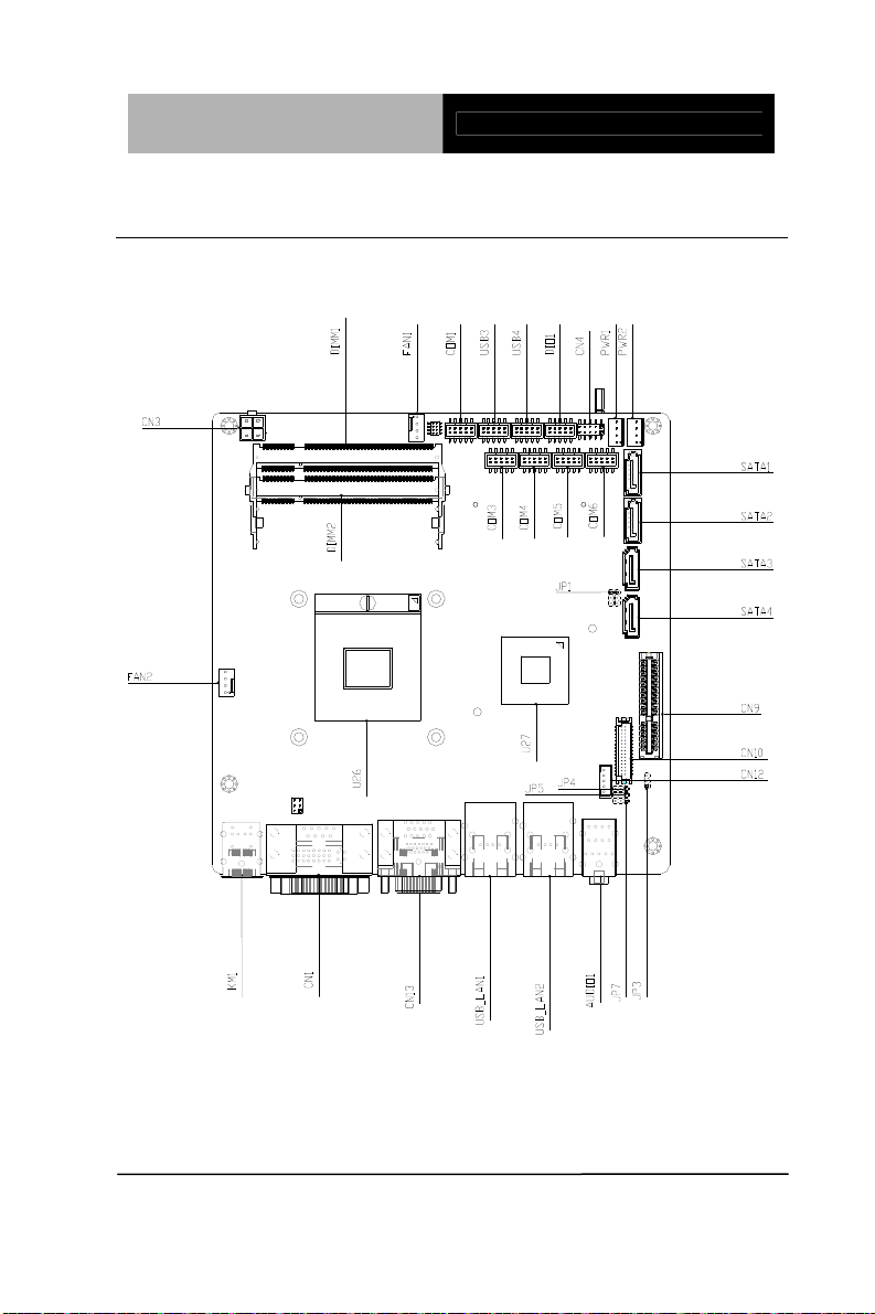
2.1 Location of Connectors (Main Board)
Component Side
AIS-E1
Chapter 2 Hardware Installation 2-2
Page 17
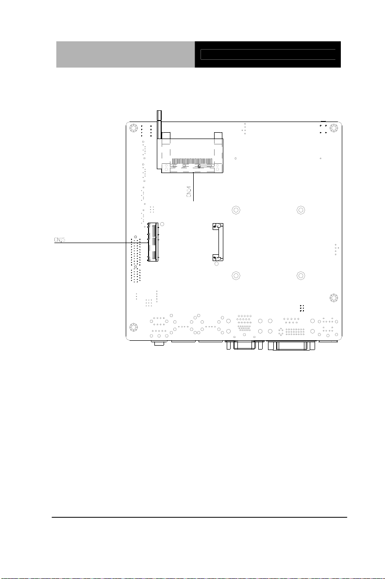
Advanced System
Controller
Solder Side
AIS-E1
Chapter 2 Hardware Installation 2-3
Page 18
Advanced System
Controller
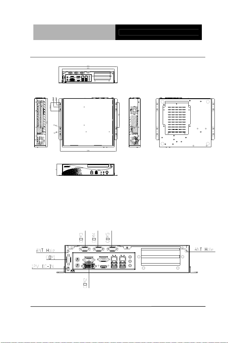
2.2 Mechanical Drawing of AIS-E1
AIS-E1
I/O Ports
Chapter 2 Hardware Installation 2-4
Page 19

Advanced System
Controller
AIS-E1
2.3 List of Jumpers
The board has a number of jumpers that allow you to configure your
system to suit your application.
The table below shows the function of each of the board's jumpers:
Label Function
JP1 Clear CMOS
JP3 Auto Power Button
JP6 +12V/+5V/RING Selection
JP7 Inverter Power Selection
2.4 List of Connectors
The board has a number of connectors that allow you to configure
your system to suit your application. The table below shows the
function of each board's connectors:
Label Function
DIO1 Digital I/O
PWR1 ~ PWR2 SATA POWER
CN1 COM2 / DVI Connector
CN3 4-pin ATX Power +12V Connector
CN4 Front Panel Connector 1
CN9 PCIE*4 Connector
CN13 VGA / HDMI Connector
CN14 CFast™ Connector
CN15 Mini Card Connector
KM1 Keyboard/Mouse Connector
COM2 RS-232/422/485 Connector
Chapter 2 Hardware Installation 2-5
Page 20

Advanced System
Controller
AIS-E1
COM1, COM3 ~ COM5 RS-232 Connector
SATA1~SATA2 SATA 3.0 Connector
SATA3~SATA4 SATA Connector
USB_LAN1 ~
USB_LAN2
DIMM1,DIMM2 DDR3 DIMM Slot
USB3 ~ USB4 USB Box Header
FAN1~ FAN2 4 Pin Fan Connector
AUDIO1 AUDIO Connector
LAN / USB Connector
Chapter 2 Hardware Installation 2-6
Page 21
Advanced System
Controller
AIS-E1
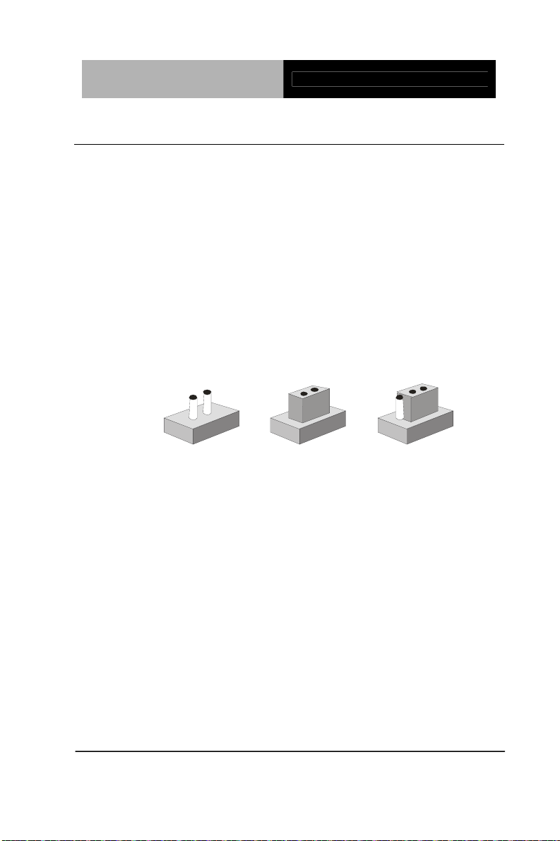
2.5 Setting Jumpers
You configure your card to match the needs of your application by
setting jumpers. A jumper is the simplest kind of electric switch. It
consists of two metal pins and a small metal clip (often protected by
a plastic cover) that slides over the pins to connect them. To “close”
a jumper you connect the pins with the clip.
To “open” a jumper you remove the clip. Sometimes a jumper will
have three pins, labeled 1, 2 and 3. In this case you would connect
either pins 1 and 2 or 2 and 3.
3
2
1
Open Closed Closed 2-3
A pair of needle-nose pliers may be helpful when working with
jumpers.
If you have any doubts about the best hardware configuration for
your application, contact your local distributor or sales
representative before you make any change.
Generally, you simply need a standard cable to make most
connections.
Chapter 2 Hardware Installation 2-7
Page 22

Advanced System
Controller
2.6 Clear CMOS (JP1)
JP1 Function
1-2 Normal (Default)
2-3 Clear CMOS
2.7 Auto Power Button (JP3)
JP3 Function
1-2 ATX (Default)
2-3 AT
2.8 +12V/+5V/Ring Selection (JP6)
JP6 Function
1-2 +12V
3-4 Ring (Default)
5-6 +5V
2.9 Inverter Power Selection (JP7)
JP7 Function
1-2 +12V (Default)
2-3 +5V
AIS-E1
2.10 Digital I/O (DIO1)
This connector offers 4-pair of digital I/O functions and address is A00H.
The pin definitions are illustrated below:
Pin Signal Pin Signal
1 Digital- IN/OUT(Port1 Bit 1) 2 Digital- IN/OUT (Port1 Bit 2)
3 Digital- IN/OUT (Port1 Bit 4) 4 Digital- IN/OUT (Port3 Bit 4)
5 Digital- IN/OUT (Port3 Bit 5) 6 Digital- IN/OUT (Port3 Bit 6)
7 Digital- IN/OUT (Port3 Bit 7) 8 Digital- IN/OUT (Port6 Bit 3)
9 +3.3V 10 GND
Chapter 2 Hardware Installation 2-8
Page 23

Advanced System
Controller
AIS-E1
The pin definitions and registers mapping are illustrated below:
Address: A00H
4 in / 4 out
Pin1 Pin2 Pin3 Pin4 Pin5 Pin6 Pin7 Pin8
GPI 11 GPI 12 GPI 14 GPI 34 GPO
35
GPO
36
GPO
37
GPO
63
8 in
Pin1 Pin2 Pin3 Pin4 Pin5 Pin6 Pin7 Pin8
GPI 11 GPI 12 GPI 14 GPI 34 GPO
35
GPO
36
GPO
37
GPO
63
8 out
Pin1 Pin2 Pin3 Pin4 Pin5 Pin6 Pin7 Pin8
GPI 11 GPI 12 GPI 14 GPI 34 GPO
35
GPO
36
GPO
37
GPO
63
2.11 SATA Power (PWR1~PWR2)
Pin Signal
1 +12V
2 GND
3 GND
4 +5V
2.12 Front Panel Connector (CN4)
4BPin 25BSignal Pin 5BSignal
1 Power On Button (-) 2 Power On Button (+)
3 HDD LED (-) 4 HDD LED (+)
5 SPEAKER(-) 6 SPEAKER(+)
7 Power LED (-) 8 Power LED (+)
9 Reset Switch (-) 10 Reset Switch (+)
Chapter 2 Hardware Installation 2-9
Page 24

Advanced System
Controller
AIS-E1
2.13 LAN1~LAN2 Active /Link/ Speed LED (CN6)
4BPin 25BSignal Pin 5BSignal
1 LAN1_LED_D2 2 LAN1_LED_LNK#_ACT
3 LAN1_LED_1000# 4 LAN1_LED_100#
5 LAN2_LED_D2 6 LAN2_LED_LNK#_ACT
7 LAN2_LED_1000# 8 LAN2_LED_100#
2.14 RS-232/422/485 Connector (COM2)
Different device implement the RS-232/422/485 standard in different ways.
If you have problems with a serial device, check the pin assignments below
for the connector.
4BPin 25BSignal Pin 5BSignal
DCD
1
(422TXD-/485DATA-)
TXD
3
(422TXD+/485DATA+)
2 RXD (422RXD+)
4 DTR (422RXD-)
5 GND 6 DSR
7 RTS 8 CTS
9 RI
2.15 RS-232 Connector (COM1, COM3~COM5)
4BPin 25BSignal Pin 5BSignal
1 DCD 2 RXD
3 TXD 4 DTR
Chapter 2 Hardware Installation 2-10
Page 25

Advanced System
Controller
AIS-E1
5 GND 6 DSR
7 RTS 8 CTS
9 RI
2.16 USB Box Header (USB3~USB4)
4BPin 25BSignal Pin 5BSignal
1 +5V 2 GND
3 USBD- 4 GND
5 USBD+ 6 USBD+
7 GND 8 USBD9 GND 10 +5V
Chapter 2 Hardware Installation 2-11
Page 26

Advanced System
Controller
2.17 Installing the Hard Disk Drive
Step 1: Unfasten the screw of the AIS-E1
AIS-E1
Step 2: Open the upper cover of the AIS-E1
Chapter 2 Hardware Installation 2-12
Page 27

Advanced System
Controller
AIS-E1
Step 3: Get the HDD Bracket and fasten the four scre ws with the
HDD
Step 4: Put the HDD and bracket back to the cha ssis by sliding the
HDD bracket and lock to the position.
Chapter 2 Hardware Installation 2-13
Page 28

Advanced System
Controller
AIS-E1
Step 5: Fasten the screw to finish in stalling the HDD
2.18 Installing Three 2.5” Hard Disk Drives
If you have three HDD to install, please refer to the installation
below.
Step 1: Unfasten the screw of the AIS-E1
Chapter 2 Hardware Installation 2-14
Page 29

Advanced System
Controller
Step 2: Open the upper cover of the AIS-E1
AIS-E1
Step 3: Put the blue rubber damper to the 3-layer HDD bracket and
move the damper to the smaller fillister (you have to put 12 blue
rubber dampers if you have three HDD to install)
Chapter 2 Hardware Installation 2-15
Page 30

Advanced System
Controller
AIS-E1
Step 4: Get the four screws ready and pierce to the dampers an d
lock the HDD (12 screws for three HDD installations)
Chapter 2 Hardware Installation 2-16
Page 31

Advanced System
Controller
AIS-E1
Step 5: Make sure that the fillisters of the 3-layer HDD bracket has
been latched to I-shape nails (blue circles)
fillister
fillister
Chapter 2 Hardware Installation 2-17
3-layer
HDD
bracket
Page 32

Advanced System
Controller
AIS-E1
Step 6: Fasten the screw to lock the HDD bra c ket with the Chassis
and you’ve done installing the three HDD
Chapter 2 Hardware Installation 2-18
Page 33

Advanced System
Controller
AIS-E1
Chapter
3
AMI
BIOS Setup
Chapter 3 AMI BIOS Setup 3-1
Page 34

Advanced System
Controller
AIS-E1
3.1 System Test and Initialization
These routines test and initialize board hardware. If the routines
encounter an error during the tests, you will either hear a few short
beeps or see an error message on the screen. There are two kinds
of errors: fatal and non-fatal. The system can usually continue the
boot up sequence with non-fatal errors.
System configuration verification
These routines check the current system configuration against the
values stored in the CMOS memory. If they do not match, the
program outputs an error message. You will then need to run the
BIOS setup program to set the configuration information in memory.
There are three situations in which you will need to change the
CMOS settings:
1. You are starting your system for the first time
2. You have changed the hardware attached to your system
3. The CMOS memory has lost power and the configuration
information has been erased.
The AIS-E1 CMOS memory has an integral lithium battery backup
for data retention. However, you will need to replace the complete
unit when it finally runs down.
Chapter 3 AMI BIOS Setup 3-2
Page 35

Advanced System
Controller
AIS-E1
3.2 AMI BIOS Setup
AMI BIOS ROM has a built-in Setup program that allows users to
modify the basic system configuration. This type of information is
stored in battery-backed CMOS RAM so that it retains the Setup
information when the power is turned off.
Entering Setup
Power on the computer and press <Del> or <F2> immediately. This
will allow you to enter Setup.
Main
Set the date, use tab to switch between date elements.
Advanced
Enable disable boot option for legacy network devices.
Chipset
Host bridge parameters.
Boot
Enables/disable quiet boot option.
Security
Set setup administrator password.
Save&Exit
Exit system setup after saving the changes.
Chapter 3 AMI BIOS Setup 3-3
Page 36

Advanced System
Controller
AIS-E1
Chapter
4
Driver
Inst
allation
.
Chapter 4 Driver Installation 4 -1
Page 37

Advanced System
Controller
AIS-E1
The AIS-E1 comes with an AutoRun DVD-ROM that contains all
drivers and utilities that can help you to install the driv
er
automatically.
Insert the driver DVD, the driver DVD-title will auto start and show
the installation guide. If not, please follow the sequence below to
install the drivers.
Follow the sequence below to install the drivers:
Step 1 – Install Chipset Driver
Step 2 – Install VGA Driver
Step 3 – Install LAN Driver
Step 4 – Install Audio Driver
Step 5 – Install ME Driver
Step 6 – Install RAID & AHCI Driver
Step 7 – Install TPM Driver
Step 8 – Install Serial Port Driver (Optional)
Note: If you got compatible issue for COM port, please find its driver under
STEP 8 folder and then install it by administrative login permission.
Please read instructions below for further detailed installations.
Chapter 4 Driver Installation 4 -2
Page 38

Advanced System
Controller
AIS-E1
4.1 Installation:
Insert the AIS-E1 DVD-ROM into the DVD-ROM drive. And install
the drivers from Step 1 to Step 8 in order.
Step 1 – Install Chipset Driver
1. Click on the STEP 1-CHIPSET folder and select the
OS folder your system is
2. Double click on the infinst_autol.exe file located in
each OS folder
3. Follow the instructions that the window shows
4. The system will help you install the driver
automatically
Step 2 – Install VGA Driver
1. Click on the STEP2-VGA folder and select the OS
folder your system is
2. Double click on the .exe file located in each OS folder
3. Follow the instructions that the window shows
4. The system will help you install the driver
automatically
Note 1:
This motherboard supports VGA and LVDS display devices. In
Single Display mode, use the hot keys to switch between VGA to
LVDS device or vice versa. By default, press
<Ctrl>+<Alt>+<F1> to switch to VGA device and press
<Ctrl>+<Alt>+<F3> to switch to LVDS device.
Before removing the current display device, connect the display
device that you want to use, and then press the hot keys to
switch to that device.
Chapter 4 Driver Installation 4 -3
Page 39

Advanced System
Controller
AIS-E1
Note 2: If the OS is Windows® XP, you have to install the driver of
dotNet Framework first. Simply click on dotnetfx35.exe located in
dotNet Framwork folder.
Step 3 –Install LAN Driver
1. Click on the STEP3-LAN folder and select the OS
folder your system is
2. Select the folder of LAN chip (Intel 82579LM or
Realtek 8111E) based on the system adopted.
Double click on the .exe file located in the LAN chip
folder
3. Follow the instructions that the window shows
4. The system will help you install the driver
automatically
Step 4 –Install Audio Driver
1. Click on the STEP4-AUDIO folder and select the OS
folder your system is
2. Double click on the Setup.exe located in each OS
folder
3. Follow the instructions that the window shows
4. The system will help you install the driver
automatically
Step 5 – Install ME Driver
1. Click on the STEP5-ME folder and select the folder of
OS folder your system is
2. Double click on the Setup.exe located in each OS
folder
3. Follow the instructions that the window shows
4.
The system will help you install the driver
Chapter 4 Driver Installation 4 -4
Page 40

Advanced System
Controller
automatically
Step 6 – Install RAID & AHCI Driver
AIS-E1
Please
refer to the Appendix C RAID & AHCI Settings
Step 7 – Install TPM Driver
1. Click on the STEP7-TPM folder and select the folder
of OS folder your system is
2. Double click on the Setup.exe located in each OS
folder
3. Follow the instructions that the window shows
4. The system will help you install the driver
automatically
Step 8 –Install Serial Port Driver (Optional)
®
For Windows
XP 32-bit
1. Click on the STEP8-Serial Port Driver (Optional)
folder and select the folder of WINXP_32
2. Double click on the patch.bat
3. Follow the instructions that the window shows
4. The system will help you install the driver
automatically
Chapter 4 Driver Installation 4 -5
Page 41

Advanced System
Controller
For Windows
®
7 32-bit/ 64-bit
AIS-E1
1. Create a password for Administrator account.
2. Change User Account Control Settings to [Never notify]
Chapter 4 Driver Installation 4 -6
Page 42

Advanced System
Controller
AIS-E1
3. Reboot and Administrator login.
4. To run patch.bat with [Run as administrator].
Chapter 4 Driver Installation 4 -7
Page 43

Advanced System
Controller
AIS-E1
You also can install the serial port driver for Windows 7 by the
Installation Proce
dure 2 below:
-Win7 32-bit
Copy the Driver CD\Serial Port Driver (Optional) \WIN7_32\
win7_X86 \serial.sys to C:\WINDOWS\system32\drivers\
-Win7 64-bit
Copy the Driver CD\Serial Port Driver (Optional) \WIN7_64
\win7_amd64\serial.sys to C:\WINDOWS\system32\drivers\
Chapter 4 Driver Installation 4 -8
Page 44

Advanced System
A
Controller
AIS-E1
Appendix
Programming the
atchdog Timer
W
Appendix A Programming the Watchdog Timer A-1
Page 45

Advanced System
Controller
AIS-E1
A.1 Programming
AIS-E1 utilizes ITE IT8728 chipset as its watchdog timer controller.
Below are the procedures to complete its configuration and the
AAEON intial watchdog timer program is also attached based on
which you can develop customized program to fit your application.
Configuring Sequence Description
After the hardware reset or power-on reset, the ITE 8728 enters the
normal mode with all logical devices disabled except KBC. The
initial state (enable bit ) of this logical device (KBC) is determined
by the state of pin 121 (DTR1#) at the falling edge of the system
reset during power-on reset.
Appendix A Programming the Watchdog Timer A-2
Page 46

Advanced System
Controller
AIS-E1
There are three steps to complete the configuration setup: (1) Enter
the MB PnP Mode; (2) Modify the data of configuration registers; (3)
Exit the MB PnP Mode. Undesired result may occur if the MB PnP
Mode is not exited normally.
(1) Enter the MB PnP Mode
To enter the MB PnP Mode, four special I/O write operations are to
be performed during Wait for Key state. To ensure the initial state of
the key-check logic, it is necessary to perform four write ope rations
to the Special Address port (2EH). Two different enter keys are
provided to select configuration ports (2Eh/2Fh) of the next step.
(2) Modify the Data of the Registers
All configuration registers can be accessed after entering the MB
PnP Mode. Before accessing a selected register, the content of
Index 07h must be changed to the LDN to which the register
belongs, except some Global registers.
(3) Exit the MB PnP Mode
Set bit 1 of the configure control register (Index=02h) to 1 to exit the
MB PnP Mode.
Appendix A Programming the Watchdog Timer A-3
Page 47

Advanced System
Controller
AIS-E1
WatchDog Timer Configuration Registers
Configure Control (Index=02h)
This register is write only. Its values are not sticky; that is to say, a
hardware reset will automatically clear the bits, and does not
require the software to clear them.
Appendix A Programming the Watchdog Timer A-4
Page 48

Advanced System
Controller
AIS-E1
WatchDog Timer Control Register (Index=71h, Default=00h)
WatchDog Timer Configuration Register (Index=72h,
Default=00h)
WatchDog Timer Time-out Value Register (Index=73h,
Default=00h)
Appendix A Programming the Watchdog Timer A-5
Page 49

Advanced System
Controller
AIS-E1
A.2 ITE8728 Watchdog Timer Initial Program
.MODEL SMALL
.CODE
Main:
CALL Enter_Configuration_mode
CALL Check_Chip
mov cl, 7
call Set_Logic_Device
;time setting
mov cl, 10 ; 10 Sec
dec al
Watch_Dog_Setting:
;Timer setting
mov al, cl
mov cl, 73h
call Superio_Set_Reg
;Clear by keyboard or mouse interrupt
mov al, 0f0h
mov cl, 71h
call Superio_Set_Reg
;unit is second.
mov al, 0C0H
mov cl, 72h
call Superio_Set_Reg
Appendix A Programming the Watchdog Timer A-6
Page 50

Advanced System
Controller
; game port enable
mov cl, 9
call Set_Logic_Device
Initial_OK:
CALL Exit_Configuration_mode
MOV AH,4Ch
INT 21h
Enter_Configuration_Mode PROC NEAR
MOV SI,WORD PTR CS:[Offset Cfg_Port]
MOV DX,02Eh
MOV CX,04h
AIS-E1
Init_1:
MOV AL,BYTE PTR CS:[SI]
OUT DX,AL
INC SI
LOOP Init_1
RET
Enter_Configuration_Mode ENDP
Exit_Configuration_Mode PROC NEAR
MOV AX,0202h
CALL Write_Configuration_Data
Appendix A Programming the Watchdog Timer A-7
Page 51

Advanced System
Controller
RET
Exit_Configuration_Mode ENDP
Check_Chip PROC NEAR
MOV AL,20h
CALL Read_Configuration_Data
CMP AL,87h
JNE Not_Initial
MOV AL,21h
CALL Read_Configuration_Data
CMP AL,12h
JNE Not_Initial
AIS-E1
Need_Initial:
STC
RET
Not_Initial:
CLC
RET
Check_Chip ENDP
Read_Configuration_Data PROC NEAR
MOV DX,WORD PTR CS:[Cfg_Port+04h]
OUT DX,AL
Appendix A Programming the Watchdog Timer A-8
Page 52

Advanced System
Controller
MOV DX,WORD PTR CS:[Cfg_Port+06h]
IN AL,DX
RET
Read_Configuration_Data ENDP
Write_Configuration_Data PROC NEAR
MOV DX,WORD PTR CS:[Cfg_Port+04h]
OUT DX,AL
XCHG AL,AH
MOV DX,WORD PTR CS:[Cfg_Port+06h]
OUT DX,AL
RET
Write_Configuration_Data ENDP
AIS-E1
Superio_Set_Reg proc near
push ax
MOV DX,WORD PTR CS:[Cfg_Port+04h]
mov al,cl
out dx,al
pop ax
inc dx
out dx,al
ret
Superio_Set_Reg endp.Set_Logic_Device proc near
Set_Logic_Device proc near
Appendix A Programming the Watchdog Timer A-9
Page 53

Advanced System
Controller
push ax
push cx
xchg al,cl
mov cl,07h
call Superio_Set_Reg
pop cx
pop ax
ret
Set_Logic_Device endp
;Select 02Eh->Index Port, 02Fh->Data Port
Cfg_Port DB 087h,001h,055h,055h
AIS-E1
DW 02Eh,02Fh
END Main
Note: Interrupt level mapping
0Fh-Dh: not valid
0Ch: IRQ12
.
.
03h: IRQ3
02h: not valid
01h: IRQ1
00h: no interrupt selected
Appendix A Programming the Watchdog Timer A-10
Page 54

Advanced System
Controller
AIS-E1
Appendix
B
I/O Information
Appendix B I/O Information B-1
Page 55

Advanced System
Controller
B.1 I/O Address Map
AIS-E1
Appendix B I/O Information B-2
Page 56

Advanced System
Controller
AIS-E1
Appendix B I/O Information B-3
Page 57

Advanced System
Controller
B.2 Memory Address Map
AIS-E1
Appendix B I/O Information B-4
Page 58

Advanced System
Controller
B.3 IRQ Mapping Chart
AIS-E1
B.4 DMA Channel Assignments
Appendix B I/O Information B-5
Page 59

Advanced System
Controller
AIS-E1
A ppendix
C
RAID & AHCI
Settings
Appendix C RAID & AHCI Settings C-1
Page 60

Advanced System
Controller
AIS-E1
C.1 Setting RAID
OS installation to setup RAID Mode
Step 1: Copy the files below from “Driver CD -> Raid Driver -> F6 Floppy -
x86” to Disk
Step 2: Connect the USB Floppy (disk with RAID files) to the board
Appendix C RAID & AHCI Settings C-2
Page 61

Advanced System
Controller
AIS-E1
Step 3: The setting procedures “ In BIOS Setup Menu”
A: Advanced -> SATA Configuration -> SATA Mode -> RAID Mode
Step 4: The setting procedures “In BIOS Setup Menu”
B: Advanced -> Launch Storage OpROM -> Enabled
Appendix C RAID & AHCI Settings C-3
Page 62

Advanced System
Controller
AIS-E1
Step 5: The setting procedures “In BIOS Setup Menu”
C: Boot -> Boot Option #1 -> DVD-ROM Type
Step 6: The setting procedures “In BIOS Setup Menu”
D: Save & Exit -> Save Changes and Exit
Appendix C RAID & AHCI Settings C-4
Page 63

Advanced System
Controller
Step 7: Press Ctrl-I to enter MAIN MENU
Step 8: Choose “1.Create RAID Volume”
AIS-E1
Appendix C RAID & AHCI Settings C-5
Page 64

Advanced System
Controller
Step 9: RAID Level -> RAID0(Stripe)
Step 10: Choose “Create Volume”
AIS-E1
Appendix C RAID & AHCI Settings C-6
Page 65

Advanced System
Controller
Step 11: Choose “Y”
Step 12: Choose “5. Exit”
AIS-E1
Appendix C RAID & AHCI Settings C-7
Page 66

Advanced System
Controller
Step 13: Choose “Y”
Step 14: Setup OS
AIS-E1
Appendix C RAID & AHCI Settings C-8
Page 67

Advanced System
Controller
Step 15: Press “F6”
Step 16: Choose “S”
AIS-E1
Appendix C RAID & AHCI Settings C-9
Page 68

Advanced System
Controller
AIS-E1
Step 17: Choose “Intel(R) ICH8M-E/ICH9M-E/5 Series SATA RAID
Controller”
Step 18: It will show the model number you select and then press “ENTER”
Appendix C RAID & AHCI Settings C-10
Page 69

Advanced System
Controller
Step 19: Setup is starting Windows
AIS-E1
Appendix C RAID & AHCI Settings C-11
Page 70

Advanced System
Controller
AIS-E1
C.2 Setting AHCI
OS installation to setup AHCI Mode
Step 1: Copy the files below from “Driver CD -> Raid Driver -> F6 Floppy -
x86” to Disk
Step 2: Connect the USB Floppy (disk with RAID files) to the board
Appendix C RAID & AHCI Settings C-12
Page 71

Advanced System
Controller
AIS-E1
Step 3: The setting procedures “ In BIOS Setup Menu”
A: Advanced -> SATA Configuration -> SATA Configuration -> SATA
Mode -> AHCI Mode
Step 4: The setting procedures “In BIOS Setup Menu”
B: Boot -> Boot Option #1 -> DVD-ROM Type
Appendix C RAID & AHCI Settings C-13
Page 72

Advanced System
Controller
AIS-E1
Step 5: The setting procedures “In BIOS Setup Menu”
C: Save & Exit -> Save Changes and Exit
Step 6: Setup OS
Appendix C RAID & AHCI Settings C-14
Page 73

Advanced System
Controller
Step 7: Press “F6”
Step 8: Choose “S”
AIS-E1
Appendix C RAID & AHCI Settings C-15
Page 74

Advanced System
Controller
AIS-E1
Step 9: Choose “Intel(R) 5 Series 6 Port SATA AHCI Controller”
tep 10: It will show the model number you select and then press “ENTER” S
Appendix C RAID & AHCI Settings C-16
Page 75

Advanced System
Controller
Step 11: Setup is loading files
AIS-E1
Appendix C RAID & AHCI Settings C-17
 Loading...