

Page 1

Touch Panel PC
AHP - 2176
AHP-2176
Onboard Intel® Celeron® 827E
1.4GHz Processor
Touch Panel PC
With 17” TFT LCD
AHP-2176 Manual 3rd Ed.
April 30, 2014
Page 2

Touch Panel PC
AHP - 2 176
Copyright Notice
This document is copyrighted, 2014. All rights are reserved. The
original manufacturer reserves the right to make improvements to
the products described in this manual at any time without notice.
No part of this manual may be reproduced, copied, translated, or
transmitted in any form or by any means without the prior written
permission of the original manufacturer. Information provided in
this manual is intended to be accurate and reliable. However, the
original manufacturer assumes no responsibility for its use, or for
any infringements upon the rights of third parties that may result
from its use.
The material in this document is for product information only and is
subject to change without notice. While reasonable efforts have
been made in the preparation of this document to assure its
accuracy, AAEON assumes no liabilities resulting from errors or
omissions in this document, or from the use of the information
contained herein.
AAEON reserves the right to make changes in the product design
without notice to its users.
i
Page 3

Touch Panel PC
AHP - 2 176
Acknowledgments
All other products’ name or trademarks are properties of their
respective owners.
AMI is a trademark of American Megatrends Inc.
Intel®, and Atom™ are trademarks of Intel® Corporation.
Microsoft Windows® is a registered trademark of Microsoft
Corp.
IBM, PC/AT, PS/2, and VGA are trademarks of International
Business Machines Corporation.
All other product names or trademarks are properties of their
respective owners.
ii
Page 4

Touch Panel PC
AHP - 2 176
Packing List
Before you begin operating your PC, please make sure that the
following materials are enclosed:
AHP-2176 Touch Panel PC
Mounting brackets and screws
DVD-ROM for manual (in PDF format) and drivers
If any of these items should be missing or damaged, please contact
your distributor or sales representative immediately.
iii
Page 5

Touch Panel PC
AHP - 2 176
Safety & Warranty
1. Read these safety instructions carefully.
2. Keep this user's manual for later reference.
3. Disconnect this equipment from any AC outlet before cleaning. Do
not use liquid or spray detergents for cleaning. Use a damp cloth.
4. For pluggable equipment, the power outlet must be installed near
the equipment and must be easily accessible.
5. Keep this equipment away from humidity.
6. Put this equipment on a firm surface during installation. Dropping
it or letting it fall could cause damage.
7. The openings on the enclosure are for air convection. Protect the
equipment from overheating. DO NOT COVER THE OPENINGS.
8. Make sure the voltage of the power source is correct before
connecting the equipment to the power outlet.
9. Position the power cord so that people cannot step on it. Do not
place anything over the power cord.
10. All cautions and warnings on the equipment should be noted.
11. If the equipment is not used for a long time, disconnect it from the
power source to avoid damage by transient over-voltage.
12. Never pour any liquid into an opening. This could cause fire or
electrical shock.
13. Never open the equipment. For safety reasons, only qualified
service personnel should open the equipment.
14. If any of the following situations arises, get the equipment
checked by service personnel:
a. The power cord or plug is damaged.
b. Liquid has penetrated into the equipment.
c. The equipment has been exposed to moisture.
iv
Page 6

Touch Panel PC
AHP - 2 176
d. The equipment does not work well, or you cannot get it
to work according to the user’s manual.
e. The equipment has been dropped and damaged.
f. The equipment has obvious signs of breakage.
15. DO NOT LEAVE THIS EQUIPMENT IN AN ENVIRONMENT
WHERE THE STORAGE TEMPERATURE IS BELOW -20°C
(-4°F) OR ABOVE 60°C (140°F). IT MAY DAMAGE THE
EQUIPMENT.
16. RESTRICTED ACCESS LOCATION: location for equipment
where both of the following apply:
a. access can only be gained by SERVICE PERSONS or by
USERS who have been instructed about the reasons for
the restrictions applied to the location and about any
precautions that shall be taken; and
b. access is through the use of a TOOL or lock and key, or
other means of security, and is controlled by the authority
responsible for the location
17. Caution: There is a danger of explosion if the battery is incorrectly
replaced. Replace only with the same or equivalent type
recommended by the manufacturer. Dispose of used batteries
according to the manufacturer’s instructions and your local
government’s recycling or disposal directives.
Attention:
Il y a un risque d’explosion si la batterie est remplacée de façon
incorrecte. Ne la remplacer qu’avec le même modèle ou équivalent
recommandé par le constructeur. Recycler les batteries usées en accord
avec les instructions du fabricant et les directives gouvernementales de
recyclage.
v
Page 7

Touch Panel PC
AHP - 2 176
FCC
This device complies with Part 15 FCC Rules.
Operation is subject to the following two
conditions: (1) this device may not cause
harmful interference, and (2) this device must
accept any interference received including
interference that may cause undesired
operation.
vi
Page 8

Touch Panel PC
AHP - 2 176
部件名称
有毒有害物质或元素
铅
(Pb)
汞
(Hg) 镉 (Cd)
六价铬
(Cr(VI))
多溴联苯
(PBB)
多溴二苯醚
(PBDE)
印刷电路板
及其电子组件
× ○ ○ ○ ○
○
外部信号
连接器及线材
× ○ ○ ○ ○
○
外壳
× ○ ○ ○ ○
○
中央处理器
与内存
× ○ ○ ○ ○
○
硬盘
× ○ ○ ○ ○ ○ 液晶模块
× ○ ○ ○ ○ ○ 光驱
× ○ ○ ○ ○ ○ 触控模块
× ○ ○ ○ ○ ○ 电源
× ○ ○ ○ ○
○
O:表示该有毒有害物质在该部件所有均质材料中的含量均在
SJ/T 11363-2006 标准规定的限量要求以下。
X:表示该有毒有害物质至少在该部件的某一均质材料中的含量超出
SJ/T 11363-2006 标准规定的限量要求。
备注:
一、此产品所标示之环保使用期限,系指在一般正常使用状况下。
二、上述部件物质中央处理器、内存、硬盘、光驱、触控模块为选购品。
Below Table for China RoHS Requirements
产品中有毒有害物质或元素名称及含量
AAEON Panel PC/ Workstation
vii
Page 9

Touch Panel PC
AHP - 2 176
Contents
Chapter 1 General Information
1.1 Introduction ................................................................ 1-2
1.2 Specification .............................................................. 1-3
1.3 Dimension ................................................................. 1-6
Chapter 2 Hardware Installation
2.1 Panelmount Installation ............................................. 2-2
2.2 Hard Disk Drive Installation ....................................... 2-4
Chapter 3 AMI BIOS Setup
3.1 System Test and Initialization ................................... 3-2
3.2 AMI BIOS Setup ........................................................ 3-3
Chapter 4 Driver Installation
4.1 Introduction ................................................................ 4-3
Appendix A Programming the Watchdog Timer
A.1 Watchdog Timer Initial Program ............................ A-2
Appendix B I/O Information
B.1 I/O Address Map .................................................. B-2
B.2 Memory Address Map .......................................... B-4
B.3 IRQ Mapping Chart .............................................. B-5
B.4 DMA Channel Assignments ................................. B-7
viii
Page 10

Touch Panel PC
A H P - 2 176
Chapter
1
General
Information
Chapter 1 General Information 1- 1
Page 11

Touch Panel PC
AHP- 2 176
1.1 Introduction
The AHP-2176 operator panel is an onboard Intel® Celeron® 827E
1.4GHz processor computer that is designed to serve as a human
machine interface (HMI). It is a PC-based system with 17" color
TFT LCD display, onboard Ethernet controller, multi-COM port
interfaces and an audio controller. With a built-in CFast™ socket,
the AHP-2176 is as compact and user friendly as a multi-function
computer. In addition, its "fit anywhere" design makes it very flexible
and able to be used in many different kinds of installations. It can be
Panel / VESA / Wallmounted.
For system integrators, this simple, complete, compact and highly
integrated system let you easily build an operator panel into your
applications. Common industrial applications include factory
automation systems, precision machinery, and production process
control. It is also suitable for many non-industrial applications,
including vending machine, and car park automation. Our operator
panel is a reliable, cost-effective solution to your application's
processing requirements.
Chapter 1 General Information 1- 2
Page 12

Touch Panel PC
A H P - 2 176
CPU
Onboard Intel® Celeron® 827E 1.4GHz
Processor
System Memory
DDR3 800/1066/1333 MHz (204 pin) x
2, SODIMM, Max. 8GB
Ethernet
10/100/1000Base-T, RJ-45 x 2
LCD / CRT Controller
Integrated in Processor
I/O Port
USB2.0 x 4 (2 on front, 2 on rear)
DB-9 RS-232 x 4 (COM3/4/5/6)
LAN x 2
VGA x 1
Line-out x 1
Power switch x 1
Storage Disk Drive
CFast™ slot x 1 (Internal);
2.5” SATA Hard Disk Drive x 1
Expansion Slot
Mini PCIe Card x 2
OS Support
Windows® CE, Windows® XP,
Windows® XP embedded, Windows® 7,
linux kernel 2.6.3 or above
Construction
IP-65 aluminum die cast front bezel
Mounting
Panel/ Wall/ VESA 100/ Desktop
1.2 Specification
System
Mechanical
Chapter 1 General Information 1-3
Page 13

Touch Panel PC
AHP- 2 176
Dimension
16.5”(W) x 14.1”(H) x 2.8”(D) (420mm x
358mm x 97mm)
Carton Dimension
26”(W) x 8.11”(H) x 19.53”(D) (661mm x
206mm x 496mm)
Net Weight
17.9 lb (8.1 kg)
Gross Weight
23.1 lb (10.5 kg)
Operating Temperature
-4oF~140oF (-20oC~60oC)
Storage Temperature
-4oF~158oF (-20oC~70oC)
Operating Humidity
5% to 95%@ 40oC, non-condensing
Vibration
1 g rms/ 5-500Hz/ Operation (HDD)
Shock
20 G peak acceleration (11 msec.
duration)
EMC
CE/FCC Class A
Power Supply
9~30V DC input ;
Over-voltage protection
Low-voltage protection
Reverse protection
DC Input
9~30V DC input ;
Over-voltage protection
Low-voltage protection
Reverse protection
Environmental
Power Supply
Chapter 1 General Information 1- 4
Page 14

Touch Panel PC
A H P - 2 176
Display Type
17” TFT LCD
Max. Resolution
1280x1024
Max. Colors
16.7M colors
Luminance (cd/m
2
)
HTT : 350
Viewing Angle
HTT: 170o (H),160o (V)
Backlight
LED
Backlight MTBF (Hours)
HTT : 50,000
Type
5-wire analog resistive
Resolution
2048x2048
Light Transmission
> 80%
Lifetime
35 million activations
LCD
Touch Screen
Chapter 1 General Information 1-5
Page 15
Touch Panel PC
AHP- 2 176
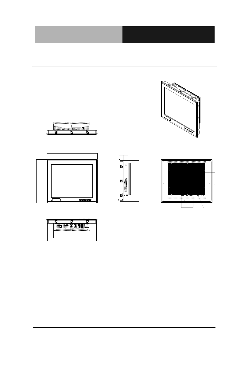
41 9.76
35 7.79
97 .3 0
AHP- 2176
10 0.00
10 0.00
40 4.03
33 8.03
VESA 10 0
30 0.00
34. 75
UNITS:m m
1.3 Dimension
Chapter 1 General Information 1- 6
Page 16

Touch Panel PC
AHP - 2 1 76
Chapter
2
Hardware
Installation
Chapter 2 Quick Installation Guide 2-1
Page 17

Touch Panel PC
AHP- 2 176
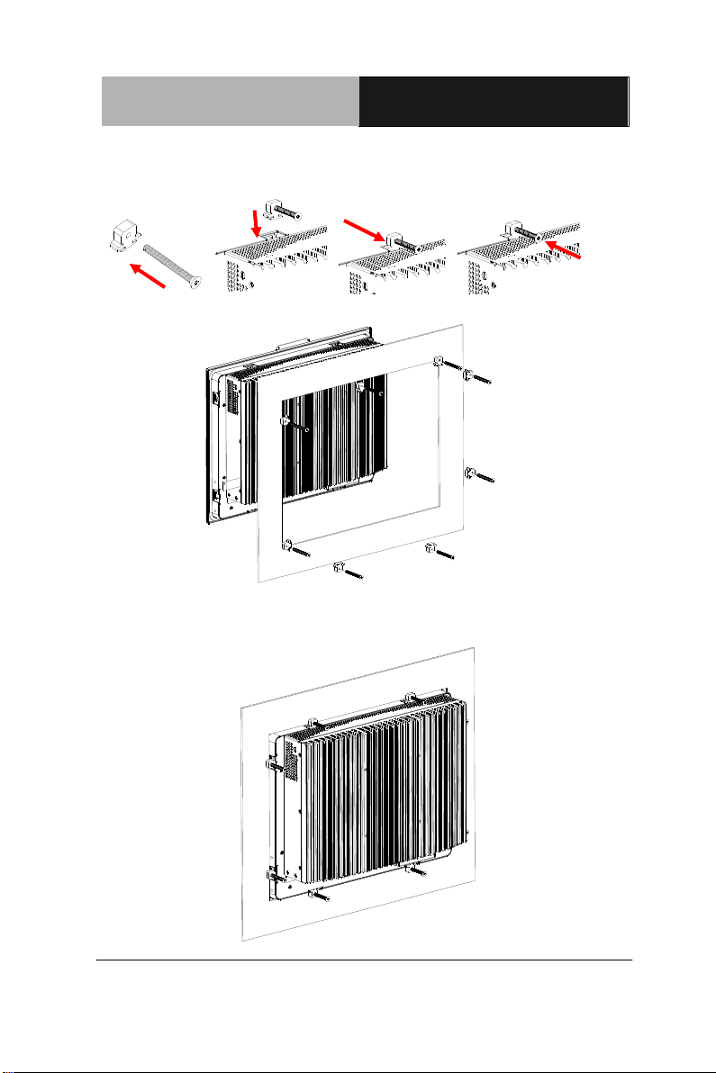
2.1 Panelmount Installation
The display panel can be mounted into the wall. You will need the
screws along with the mounting brackets, which be packed in the
accessory box. Follow the steps below:
Before you start to follow the instructions, please place the
display panel into the wall. See the following illustration on the
left.
Step 1: Place the mounting brackets and plug the screw.
Step 2: Aim the mounting set at the hole on the monitor.
Step 3: Move the mounting set to the narrow gauge and fix it with
screws.
Step 4: You’ve completed the preliminary when the mounting set
is tightened. Next, repeat the steps and tighten all mounting set
around the monitor until the monitor is firmly mounting on the
wall.
Chapter 2 Quick Installation Guide 2 - 2
Page 18
Touch Panel PC
AHP - 2 1 76
2 - 3
1 2 3 4
Complete Illustration
Chapter 2 Quick Installation Guide
Page 19

Touch Panel PC
AHP- 2 176
Pin
2BSignal
Pin
3BSignal
1
DCD
2
RXD
3
TXD
4
DTR
5
GND
6
DSR
7
RTS
8
CTS
9
RI
1 2 5
6 7 8 9 4
2.2 COM Port Connector
Chapter 2 Quick Installation Guide 2 - 4
Page 20
Touch Panel PC
AHP - 2 1 76
2 - 5
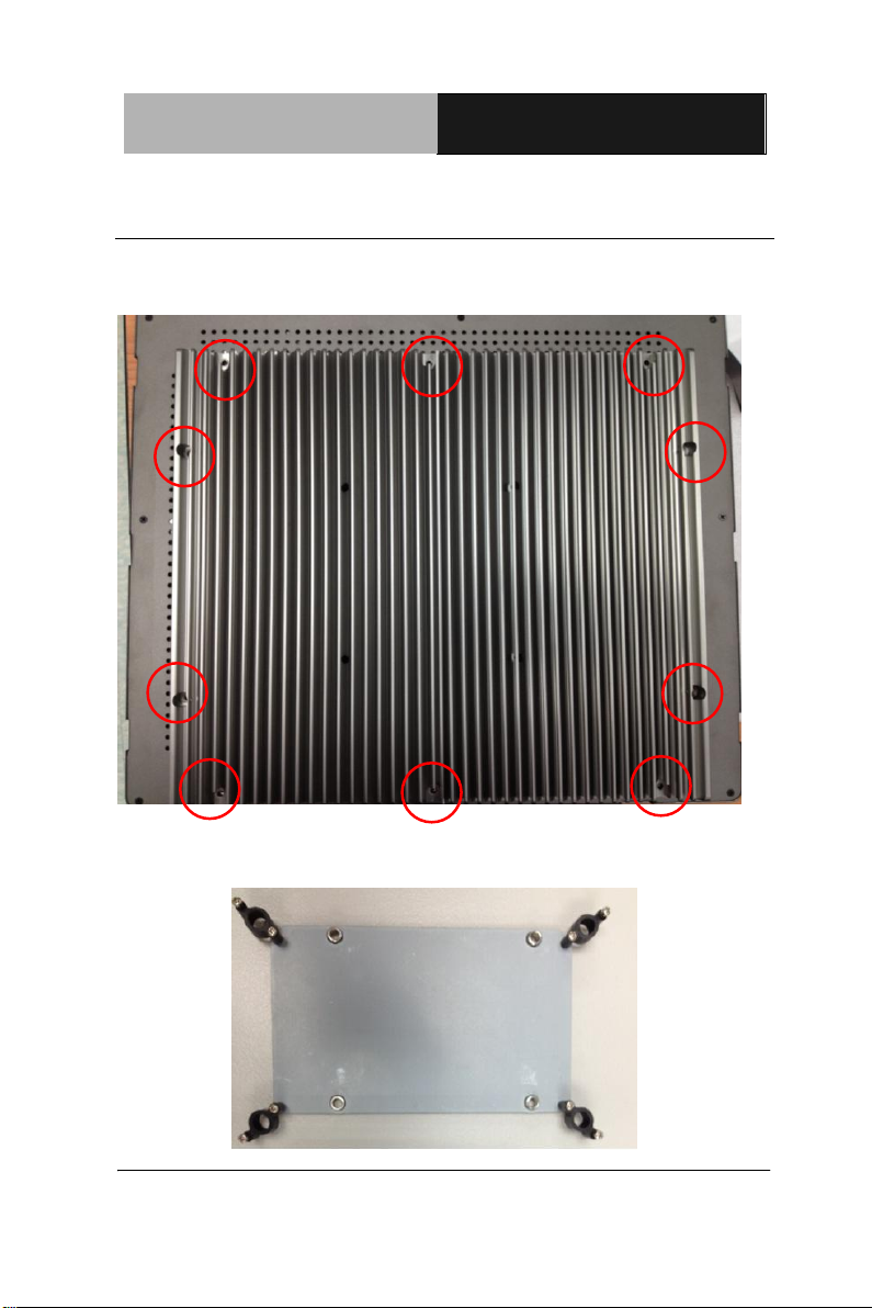
2.3 Hard Disk Drive Installation
Step 1: Unfasten the screws of the heatsink
Step 2: Get the Bracket of Hard Disk Drive from the package
Chapter 2 Quick Installation Guide
Page 21
Touch Panel PC
AHP- 2 176
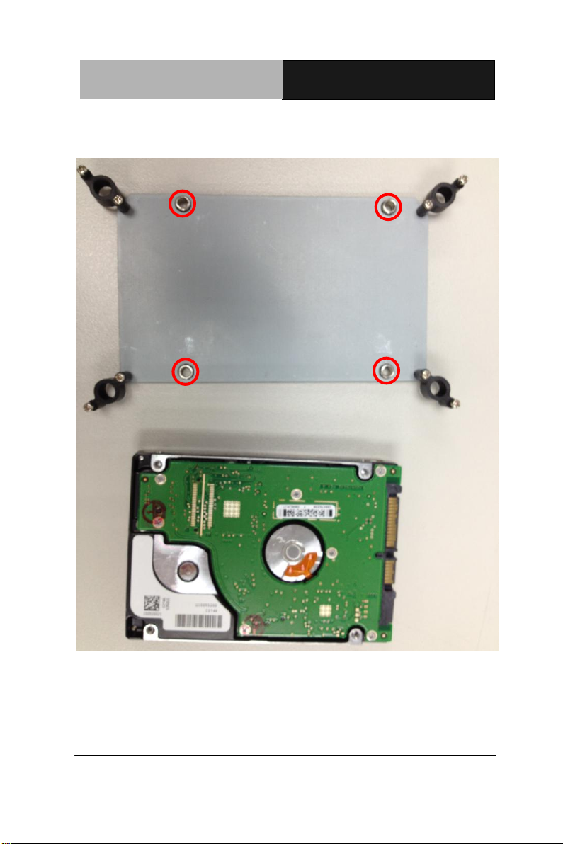
Step 3: Fasten the Hard Disk onto the bracket
Chapter 2 Quick Installation Guide 2 - 6
Page 22
Touch Panel PC
AHP - 2 1 76
2 - 7
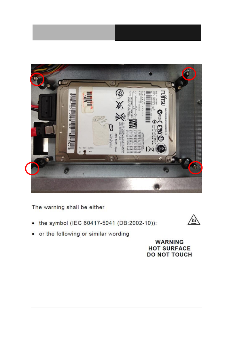
Step 4: Fasten the screws of the hard disk bracket onto the AHP-2176
Chapter 2 Quick Installation Guide
Page 23

Touch Panel PC AHP-2176
Chapter
3
AMI
BIOS Setup
Chapter 3 AMI BIOS Setup 3-1
Page 24

Touch Panel PC AHP-2176
3.1 System Test and Initialization
These routines test and initialize board hardware. If the routines
encounter an error during the tests, you will either hear a few short
beeps or see an error message on the screen. There are two kinds
of errors: fatal and non-fatal. The system can usually continue the
boot up sequence with non-fatal errors.
System configuration verification
These routines check the current system configuration stored in the
CMOS memory and BIOS NVRAM. If system configuration is not
found or system configuration data error is detected, system will
load optimized default and re-boot with this default system
configuration automatically.
There are four situations in which you will need to setup system
configuration:
1. You are starting your system for the first time
2. You have changed the hardware attached to your system
3. The system configuration is reset by Clear-CMOS jumper
4. The CMOS memory has lost power and the configuration
information has been erased.
The AHP-2176 CMOS memory has an integral lithium battery
backup for data retention. However, you will need to replace the
complete unit when it finally runs down.
Chapter 3 AMI BIOS Setup 3-2
Page 25

Touch Panel PC AHP-2176
3.2 AMI BIOS Setup
AMI BIOS ROM has a built-in Setup program that allows users to
modify the basic system configuration. This type of information is
stored in battery-backed CMOS RAM and BIOS NVRAM so that it
retains the Setup information when the power is turned off.
Entering Setup
Power on the computer and press <Del>or <F2> immediately. This
will allow you to enter Setup.
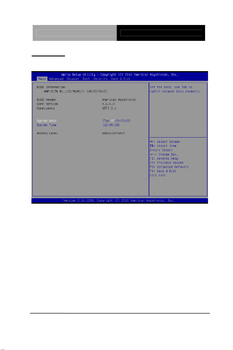
Main
Set the date, use tab to switch between date elements.
Advanced
Enable disable boot option for legacy network devices.
Chipset
Host bridge parameters.
Boot
Enables/disable quiet boot option.
Security
Set setup administrator password.
Save&Exit
Exit system setup after saving the changes.
Chapter 3 AMI BIOS Setup 3-3
Page 26
Touch Panel PC AHP-2176
Setup Menu
Setup submenu: Main
Chapter 3 AMI BIOS Setup 3-4
Page 27
Touch Panel PC AHP-2176
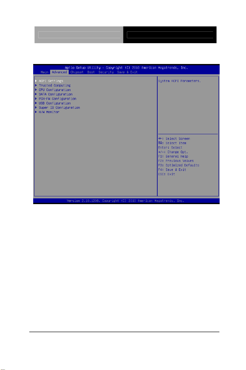
Setup submenu: Advanced
Chapter 3 AMI BIOS Setup 3-5
Page 28
Touch Panel PC AHP-2176
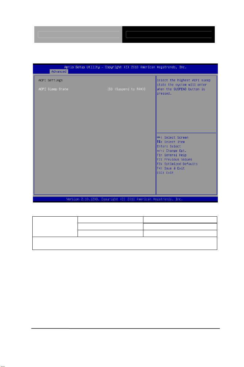
ACPI Settings
Options Summary :
ACPI Sleep State
Select the Highest ACPI sleep state the system will enter when the
SUSPEND button is pressed.
Suspend Disabled
S1 (CPU Stop Clock)
S3 (Suspend to RAM) Default
Chapter 3 AMI BIOS Setup 3-6
Page 29

Touch Panel PC AHP-2176
Trusted Computing
Option Summary :
Disable Default TPM SUPPORT
Enable
Enables or Disables TPM support. O.S. will not show TPM. Reset of
platform is required.
Chapter 3 AMI BIOS Setup 3-7
Page 30
Touch Panel PC AHP-2176
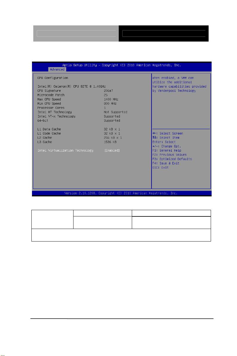
CPU Configuration
Options Summary :
Disabled Intel
Virtualization
Technology
When enabled, a VMM can utilize the additional hardware capabilities
provided by Vanderpool Techn ology
Enabled Default
Chapter 3 AMI BIOS Setup 3-8
Page 31
Touch Panel PC AHP-2176
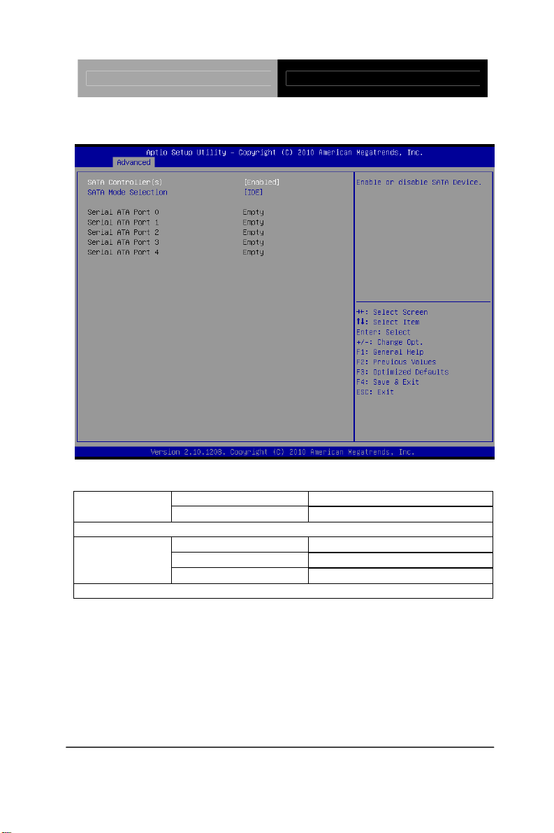
SA TA Configuration (IDE)
Options Summary :
Enabled Default SATA
Controller(s)
Enable or disable SATA Device.
SATA Mode
Selection
Determines how SATA controller(s) operate.
Disabled
IDE Default
AHCI
RAID
Chapter 3 AMI BIOS Setup 3-9
Page 32
Touch Panel PC AHP-2176
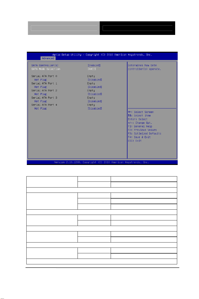
IDE Configuration (AHCI)
Options Summary :
Disabled SATA Controller(s)
Enabled Default
Enable or Disable SATA Port.
SATA Mode Selection
Determines how SATA controller(s) operate.
Designates this port as Hot Pluggable.
Designates this port as Hot Pluggable.
Designates this port as Hot Pluggable.
IDE
AHCI Selected
RAID
Disable Default SATA Port 0 Hot Plug
Enabled
Disable Default SATA Port 1 Hot Plug
Enabled
Disable Default SATA Port 2 Hot Plug
Enabled
Chapter 3 AMI BIOS Setup 3-10
Page 33

Touch Panel PC AHP-2176
Disable Default SATA Port 3 Hot Plug
Enabled
Designates this port as Hot Pluggable.
Disable Default SATA Port 4 Hot Plug
Enabled
Designates this port as Hot Pluggable.
Chapter 3 AMI BIOS Setup 3-11
Page 34

Touch Panel PC AHP-2176
IDE Configuration (RAID)
Options Summary :
Disabled SATA Controller(s)
Enabled Default
Enable or Disable SATA Port.
SATA Mode
Determines how SATA controller(s) operate.
Designates this port as Hot Pluggable.
Designates this port as Hot Pluggable.
Designates this port as Hot Pluggable.
IDE
AHCI
RAID Selected
Disable Default SATA Port 0 Hot Plug
Enabled
Disable Default SATA Port 1 Hot Plug
Enabled
Disable Default SATA Port 2 Hot Plug
Enabled
Chapter 3 AMI BIOS Setup 3-12
Page 35

Touch Panel PC AHP-2176
Disable Default SATA Port 3 Hot Plug
Enabled
Designates this port as Hot Pluggable.
Disable Default SATA Port 4 Hot Plug
Enabled
Designates this port as Hot Pluggable.
Chapter 3 AMI BIOS Setup 3-13
Page 36

Touch Panel PC AHP-2176
PCH-FW Configuration
Options Summary :
Firmware
Update
Configuration
Configure Management Engine Technology Parameters.
Chapter 3 AMI BIOS Setup 3-14
Page 37
Touch Panel PC AHP-2176
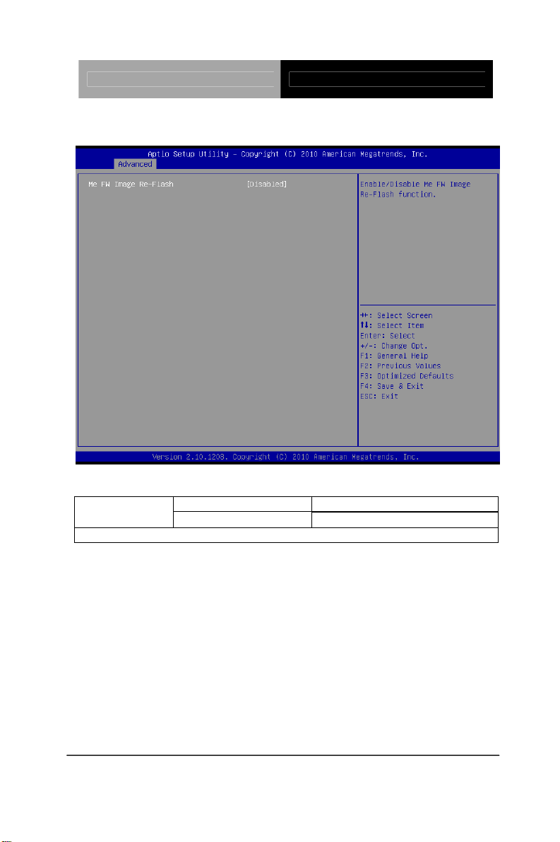
Firmware Update Configuration
Options Summary :
Disabled Default Me FW Image
Re-Flash
Enable/Disable Me FW Image Re-Flash function.
Enabled
Chapter 3 AMI BIOS Setup 3-15
Page 38

Touch Panel PC AHP-2176
USB Configuration
Options Summary :
Legacy USB Support
Enable Legacy USB support.
AUTO option disables legacy support if no USB devices are connected.
DISABLE option will keep USB devices available only for EFI applications.
Enabled Default
Disabled
Auto
Chapter 3 AMI BIOS Setup 3-16
Page 39
Touch Panel PC AHP-2176
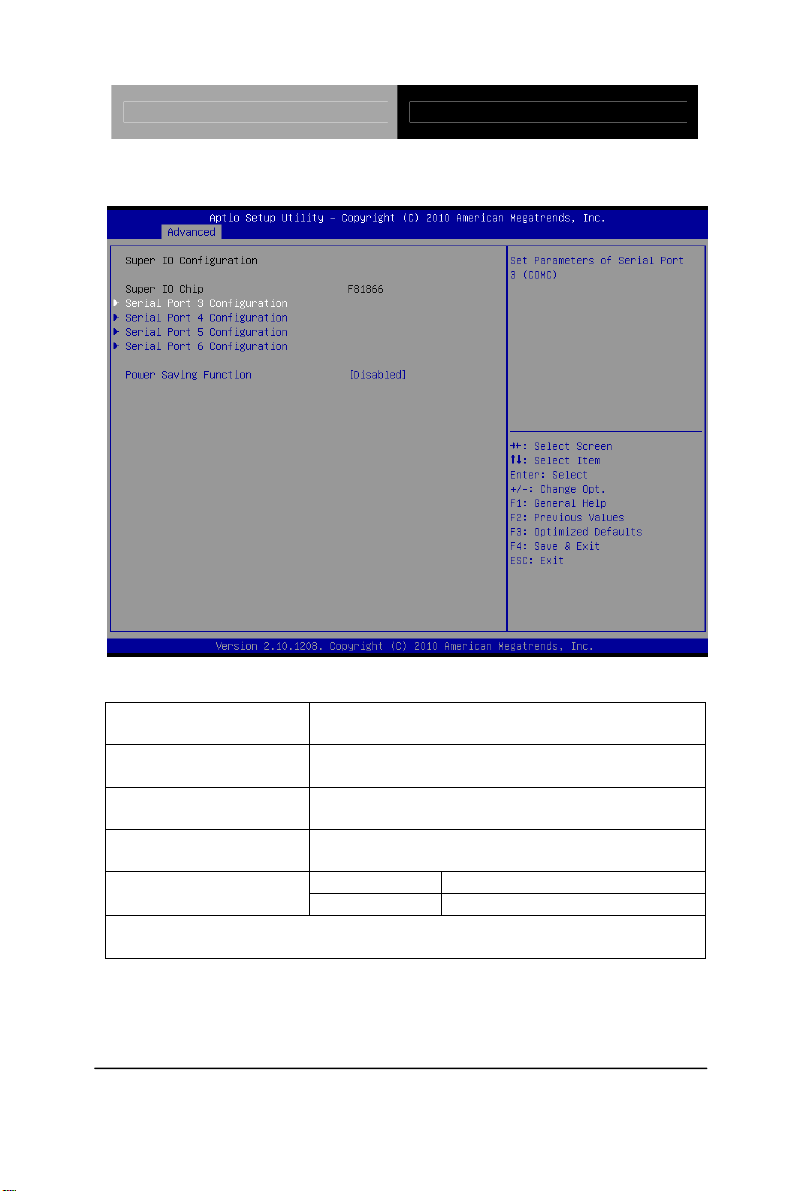
Super IO Configuration
Options Summary :
Serial Port 3
Configuration
Serial Port 4
Configuration
Serial Port 5
Configuration
Serial Port 6
Configuration
Enable to reduce power consumption is system off state.
When Enabled, only power button can power-up system.
Set Parameters of Serial Port 3 (COMC)
Set Parameters of Serial Port 4 (COMD)
Set Parameters of Serial Port 5 (COME)
Set Parameters of Serial Port 6 (COMF)
Disabled Default Power Saving Function
Enabled
Chapter 3 AMI BIOS Setup 3-17
Page 40

Touch Panel PC AHP-2176
Serial Port 3 Configuration
Options Summary :
Enabled Default Serial Port
Disabled
Enable or Disable Serial Port (COM)
Change Settings
Select an optimal setting for Super IO device.
Auto Default
IO=3E8h; IRQ=5;
IO=2E8h; IRQ=5;
IO=2D0h; IRQ=5’
IO=2D8h; IRQ=5;
Chapter 3 AMI BIOS Setup 3-18
Page 41

Touch Panel PC AHP-2176
Serial Port 4 Configuration
Options Summary :
Enabled Default Serial Port
Disabled
Enable or Disable Serial Port (COM)
Change Settings
Select an optimal setting for Super IO device.
Auto Default
IO=2E8h; IRQ=5;
IO=3E8h; IRQ=5;
IO=2D0h; IRQ=5;
IO=2D8h; IRQ=5;
Chapter 3 AMI BIOS Setup 3-19
Page 42
Touch Panel PC AHP-2176
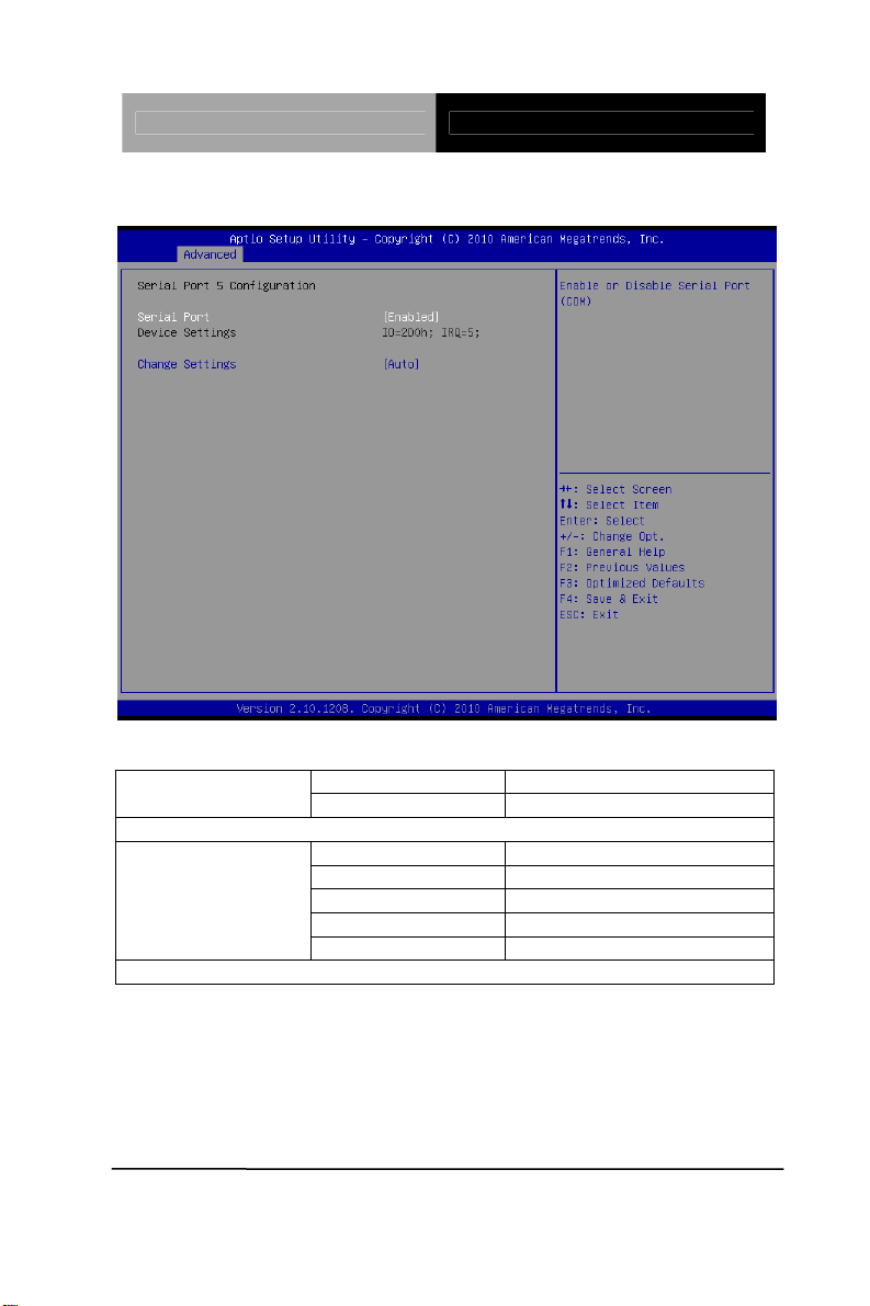
Serial Port 5 Configuration
Options Summary :
Enabled Default Serial Port
Disabled
Enable or Disable Serial Port (COM)
Change Settings
Select an optimal setting for Super IO device.
Auto Default
IO=2D0h; IRQ=5;
IO=3E8h; IRQ=5;
IO=2E8h; IRQ=5;
IO=2D8h; IRQ=5;
Chapter 3 AMI BIOS Setup 3-20
Page 43

Touch Panel PC AHP-2176
Serial Port 6 Configuration
Options Summary :
Enabled Default Serial Port
Disabled
Enable or Disable Serial Port (COM)
Change Settings
Select an optimal setting for Super IO device.
Auto Default
IO=2D8h; IRQ=5
IO=3E8h; IRQ=5;
IO=2E8h; IRQ=5;
IO=2D0h; IRQ=5;
Chapter 3 AMI BIOS Setup 3-21
Page 44
Touch Panel PC AHP-2176
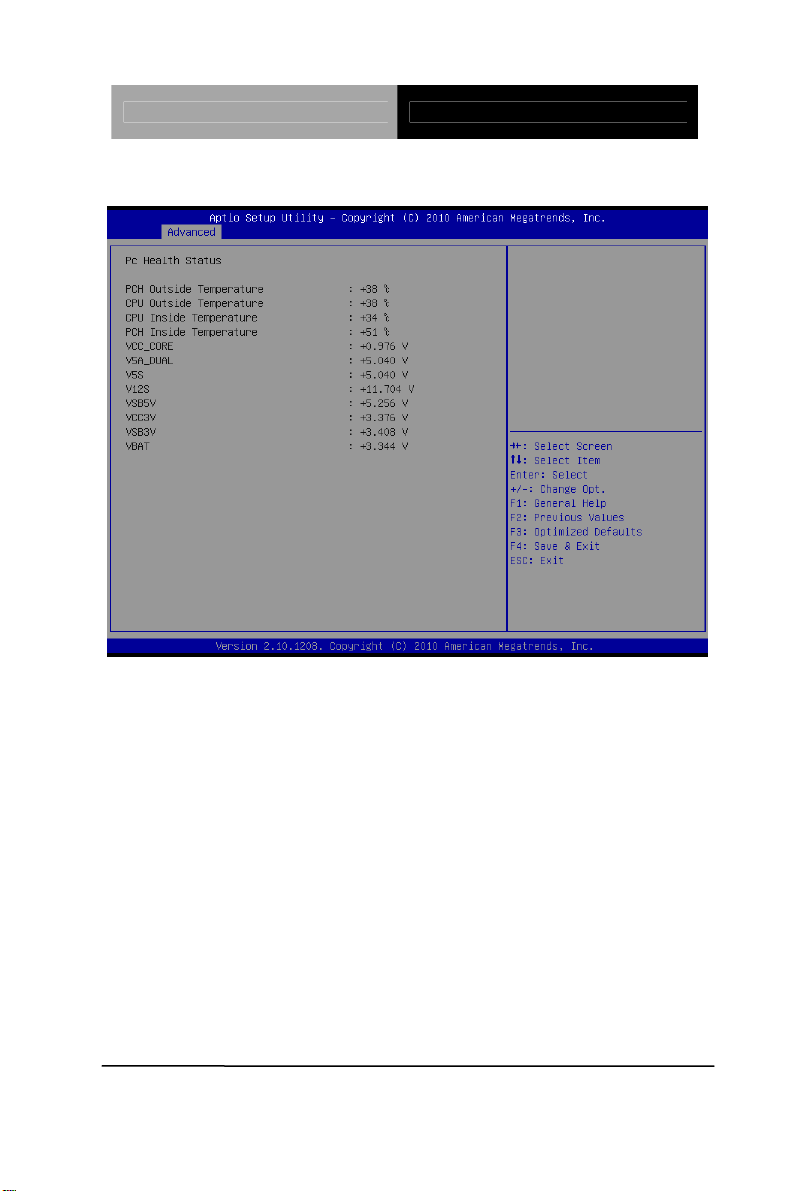
H/W Monitor
Chapter 3 AMI BIOS Setup 3-22
Page 45
Touch Panel PC AHP-2176
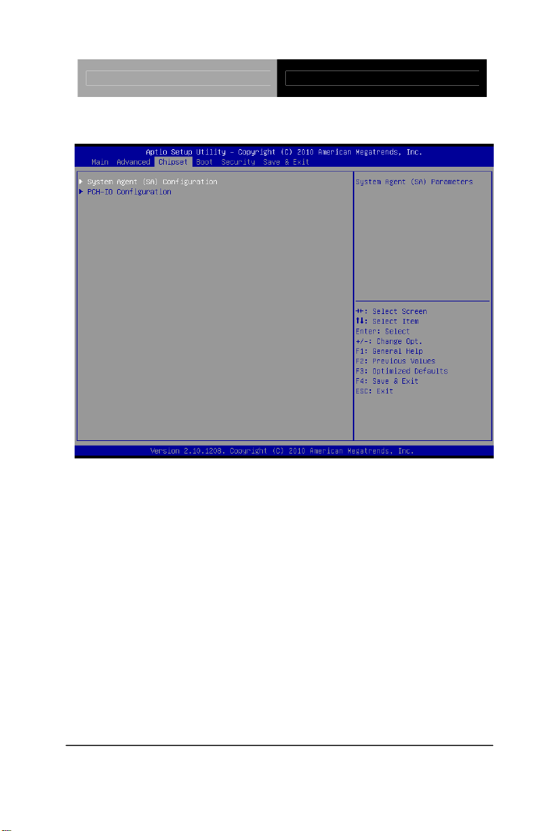
Setup submenu: Chipset
Chapter 3 AMI BIOS Setup 3-23
Page 46

Touch Panel PC AHP-2176
System Agent (SA) Configuration
Options Summary :
Graphics
Configuration
Config Graphics Settings.
Chapter 3 AMI BIOS Setup 3-24
Page 47

Touch Panel PC AHP-2176
Graphics Configuration
Options Summary :
Internal Graphics
Keep IGD enabled based on the setup options.
DVMT Pre-Allocated
Auto Default
Disabled
Enabled
0M
32M
64M Default
96M
128M
160M
192M
224M
256M
288M
320M
352M
Chapter 3 AMI BIOS Setup 3-25
Page 48

Touch Panel PC AHP-2176
384M
416M
448M
480M
512M
Select DVMT 5.0 Pre-Allocated (Fixed) Graphics Memory size used by the
Internal Graphics Device.
DVMT Total Gfx Men
Select DVMT5.0 Total Graphic Memory size used by the Internal Graphics
Device.
128M
256M
MAX Default
Chapter 3 AMI BIOS Setup 3-26
Page 49
Touch Panel PC AHP-2176
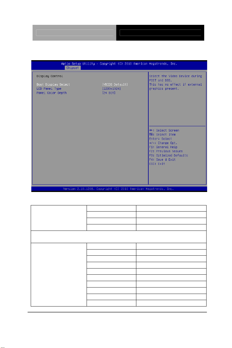
Display Control
Options Summary :
Boot Display Select
Select the Video Device during POST and DOS.
This has no effect if external graphics present.
LCD Panel Type
VBIOS Default Default
CRT
LVDS
CRT+LVDS
640x480
800x480
800x600
1024x768
1280x1024 Default
1600x1200
1366x768
1680x1050
1920x1200
1440x900
Chapter 3 AMI BIOS Setup 3-27
Page 50

Touch Panel PC AHP-2176
1680x1050
1280x800
1920x1080
Select LCD panel used by Internal Graphics Device by selecting the
appropriate setup items.
18 bit Panel Color Depth
24 bit
Select the LFP Panel Color Depth
Chapter 3 AMI BIOS Setup 3-28
Page 51
Touch Panel PC AHP-2176
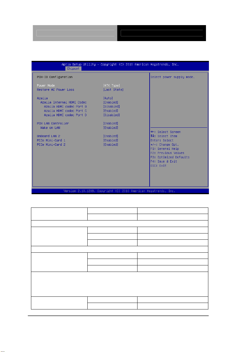
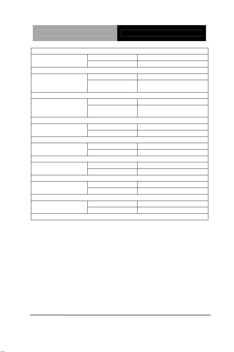
PCH-IO Configuration
Options Summary :
A TX Type Default Power Mode
AT T y pe
Select power supply mode.
Restore AC Power
Loss
Select AC power state when power is re-applied after a power failure.
Azalia
Control Detection of the Azalia device.
Disabled = Azalia will be unconditionally disabled
Enabled = Azalia will be unconditionally Enabled
Auto = Azalia will be enabled if present, disabled otherwise.
Codec
Power off
Power on
Last State Default
Disabled
Enabled
Auto Default
Disabled Azalia Internal HDMI
Enabled Default
Chapter 3 AMI BIOS Setup 3-29
Page 52
Touch Panel PC AHP-2176
Enable or disable internal HDMI codec for Azalia.
Disabled Default Azalia HDMI codec
Port B
Enable or disable internal HDMI codec Port for Azalia.
Port C
Enable or disable internal HDMI codec Port for Azalia.
Port D
Enable or disable internal HDMI codec Port for Azalia.
Enable or disable onboard NIC.
Enable or disable integrated LAN to wake the system.
OnBoard LAN 2 RTL8111E LAN En/Disable Control
Enable / Disable PCIe Mini-Card 1
Enable / Disable PCIe Mini-Card 2
Enabled
Disabled Azalia HDMI codec
Enabled Default
Disabled Default Azalia HDMI codec
Enabled
Enabled Default PCH LAN Controller
Disabled
Enabled Default Wake on LAN
Disabled
Disabled OnBoard LAN 2
Enabled Default
Disabled PCIe Mini-Card 1
Enabled Default
Disabled PCIe Mini-Card 2
Enabled Default
Chapter 3 AMI BIOS Setup 3-30
Page 53

Touch Panel PC AHP-2176
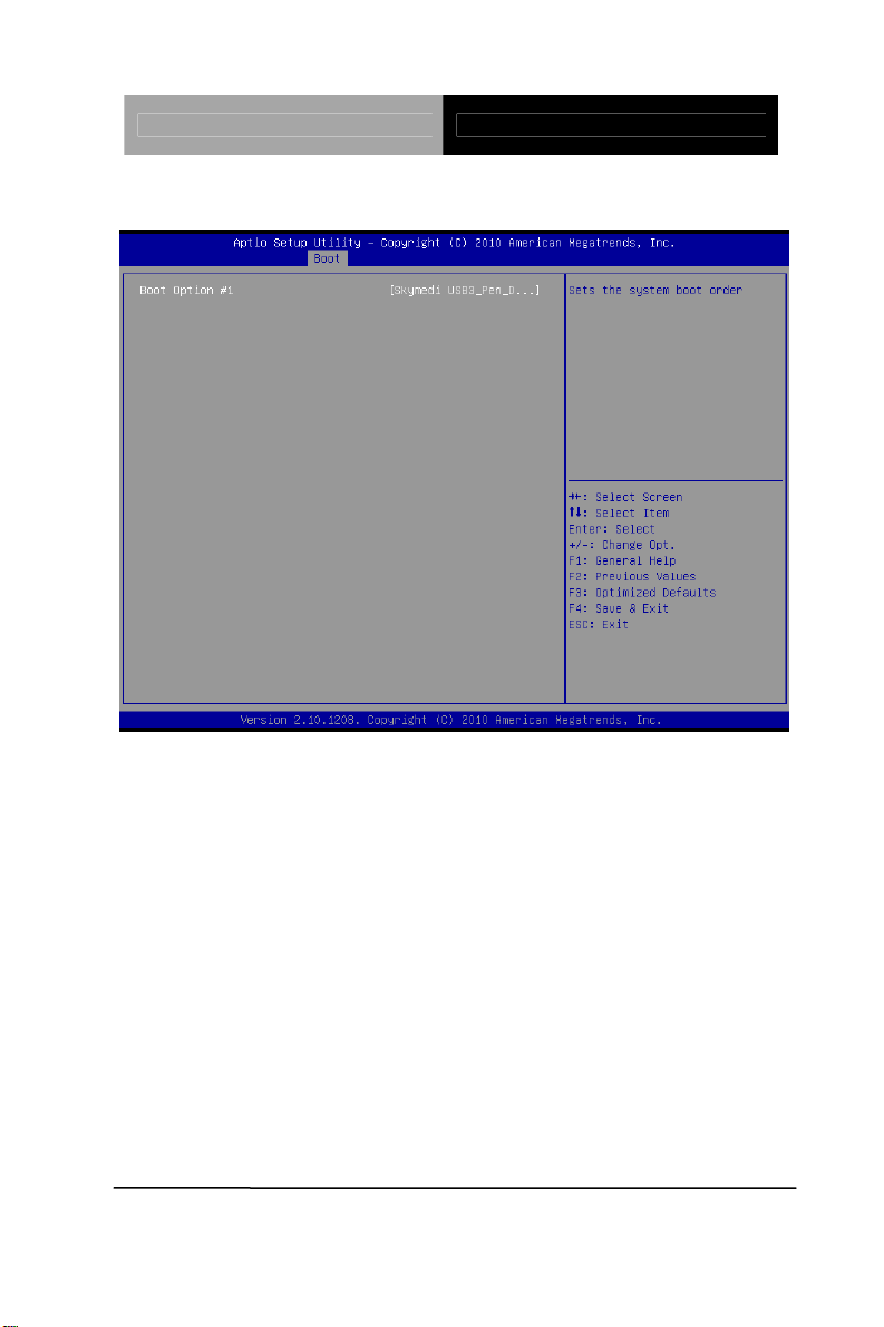
Setup submenu: Boot
Options Summary :
Disabled Quiet Boot
Enabled Default
Enables or disables Quiet Boot option
Disabled Default Launch I82579LM PXE
OpROM
Enable or Disable Legacy Boot Option for I82579LM.
PXE OpROM
Enable or Disable Legacy Boot Option for RTL8111E
Boot options #X Your storage/disk devices
Enabled
Disabled Default Launch RTL8111E
Enabled
Sets the system boot order
Chapter 3 AMI BIOS Setup 3-31
Page 54
Touch Panel PC AHP-2176
Hard Drives BBS Priorities
Chapter 3 AMI BIOS Setup 3-32
Page 55
Touch Panel PC AHP-2176
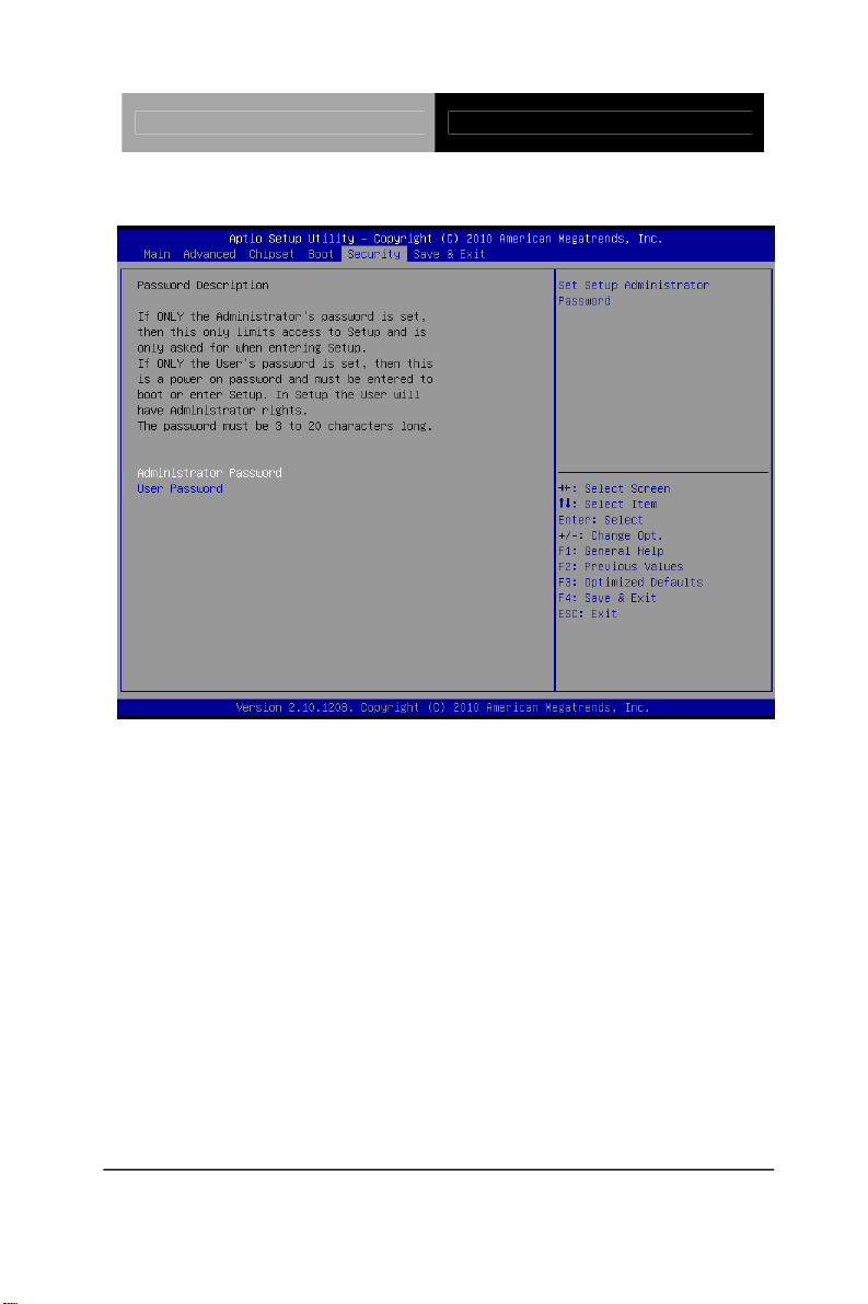
Submenu: Security
Change User/Supervisor Password
You can install a Supervisor password, and if you install a supervisor
password, you can then install a user password. A user password does
not provide access to many of the features in the Setup utility.
If you highlight these items and press Enter, a dialog box appears which
lets you enter a password. You can enter no more than six letters or
numbers. Press Enter after you have typed in the password. A second
dialog box asks you to retype the password for confirmation. Press Enter
after you have retyped it correctly. The password is required at boot time,
or when the user enters the Setup utility.
Removing the Password
Highlight this item and type in the current password. At the next dialog
box press Enter to disable password protection.
Chapter 3 AMI BIOS Setup 3-33
Page 56
Touch Panel PC AHP-2176
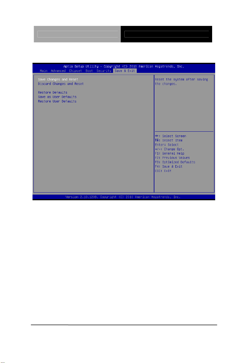
Setup submenu: Exit
Chapter 3 AMI BIOS Setup 3-34
Page 57

Touch Panel PC AHP-2176
Chapter
4
Driver
Inst
.
Chapter 4 Driver Installation 4 -1
allation
Page 58

Touch Panel PC AHP-2176
The AHP-2176 comes with an AutoRun DVD-ROM that contains all
drivers and utilities that can help you to install the driv
er
automatically.
Insert the driver DVD, the driver DVD-title will auto start and show
the installation guide. If not, please follow the sequence below to
install the drivers.
Follow the sequence below to install the drivers:
Step 1 – Install Chipset Driver
Step 2 – Install VGA Driver
Step 3 – Install Audio Driver
Step 4 – Install LAN Driver
Step 5 – Install ME Driver
Step 6 – Install TPM Driver
Step 7 – Install Touch Panel Driver
Step 8 – Install Serial Port Driver (Optional)
Note: If you got compatible issue for COM port, please find its driver under
STEP 8 folder and then install it by administrative login permission.
Please read instructions below for further detailed installations.
Chapter 4 Driver Installation 4 -2
Page 59

Touch Panel PC AHP-2176
4.1 Installation:
Insert the AHP-2176 DVD-ROM into the DVD-ROM drive. And
install the drivers from Step 1 to Step 8 in order.
Step 1 – Install Chipset Driver
1. Click on the STEP 1-CHIPSET folder and double cli ck on
the infinst_autol.exe file
2. Follow the instructions that the window shows
3. The system will help you install the driver automatically
Step 2 – Install VGA Driver
1. Click on the STEP2-VGA folder and select the OS folder
your system is
2. Double click on the .exe file located in each OS
folder
3. Follow the instructions that the window shows
4. The system will help you install the driver automatically
Note 1:
This motherboard supports VGA and LVDS display devices. In
Single Display mode, use the hot keys to switch between VGA to
LVDS device or vice versa. By default, press
<Ctrl>+<Alt>+<F1> to switch to VGA device and press
<Ctrl>+<Alt>+<F3> to switch to LVDS device.
Before removing the current display device, connect the display
device that you want to use, and then press the hot keys to
switch to that device.
Note 2:
dotNet Framework first. Simply click on dotnetfx35.exe located in
If the OS is Windows® XP, you have to install the driver of
Chapter 4 Driver Installation 4 -3
Page 60

Touch Panel PC AHP-2176
dotNet Framwork folder.
Step 3 –Install Audio Driver
1. Click on the STEP3-AUDIO folder and select the OS folder
your system is
2. Double click on the .exe located in each OS folder
3. Follow the instructions that the window shows
4. The system will help you install the driver automatically
Step 4 –Install LAN Driver
1. Click on the STEP4-LAN folder and select the folder of
intel_82579 or realtek_8111E based on the LAN chipset in
your system.
2. Select the OS folder your system is located in the chipset
folder, then double click on .exe file located in each OS
folder
3. Follow the instructions that the window shows
4. The system will help you install the driver automatically
Step 5 – Install ME Driver
1. Click on the STEP5-ME folder and double click on the
setup.exe file
2. Follow the instructions that the window shows
3. The system will help you install the driver automatically
Chapter 4 Driver Installation 4 -4
Page 61

Touch Panel PC AHP-2176
Step 6 – Install TPM Driver
Click on the STEP6-TPM folder and double click on the
1.
Setup.exe file
2. Follow the instructions that the window shows
3. The system will help you install the driver automatically
Step 7 – Install Touch Panel Driver
1. Click on the STEP7-Touch Panel Driver folder a nd select
the OS folder your system is
2. Double click on the setup.exe file located in each OS
folder
3. Follow the instructions that the window shows
4. The system will help you install the driver automatically
Step 8 –Install Serial Port Driver (Optional)
®
For Windows
XP 32-bit, select the folder of WINXP_32 and double
click on the patch.bat
For Windows
®
7, please refer to the installation procedures below.
Chapter 4 Driver Installation 4 -5
Page 62
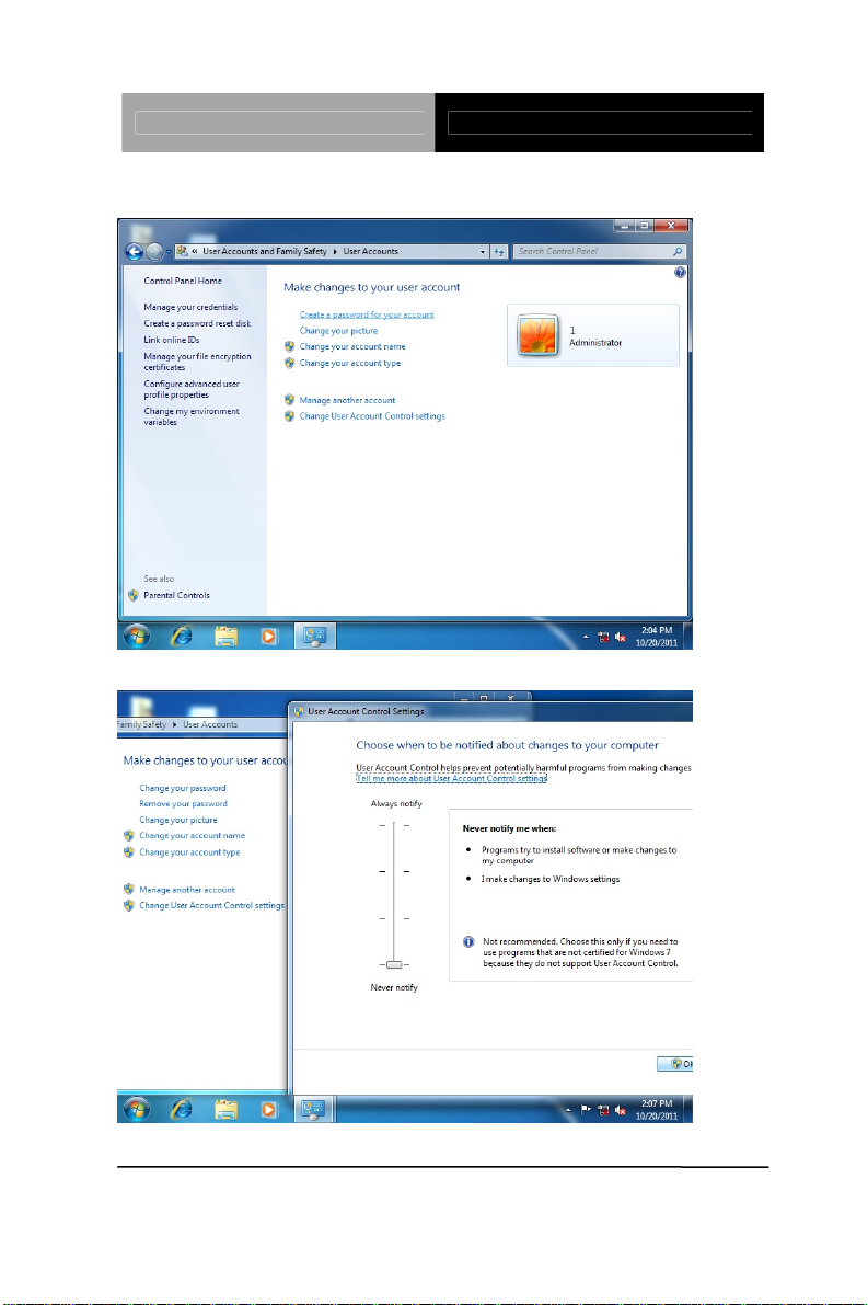
Touch Panel PC AHP-2176
1. Create a password for Administrator account.
2. Change User Account Control Settings to [Never notify]
Chapter 4 Driver Installation 4 -6
Page 63
Touch Panel PC AHP-2176
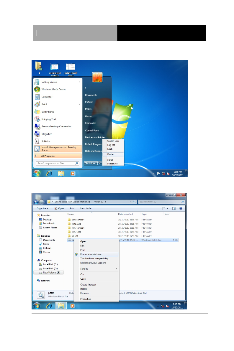
3. Reboot and Administrator login.
4. To run patch.bat with [Run as administrator].
Chapter 4 Driver Installation 4 -7
Page 64

Touch Panel PC AHP-2176
Chapter 4 Driver Installation 4 -8
Page 65

Touch Panel PC AHP-2176
A
Appendix
Programming the
atchdog Timer
W
Appendix A Programming the Watchdog Timer A-1
Page 66

Touch Panel PC AHP-2176
A.1 Watchdog Timer Initial Program
Table 1 : SuperIO relative register table
Default Value Note
Index 0x2E(Note1)
Data 0x2F(Note2)
SIO MB PnP Mode Index Register
0x2E or 0x4E
SIO MB PnP Mode Data Register
0x2F or 0x4F
Table 2 : Watchdog relative register table
LDN Register BitNum Value Note
Time of watchdog
Timer
Counter
Counting
Unit
Watchdog
Enable
Timeout
Status
Output
Mode
WDTRST
output
0x07
(Note3)
0x07
(Note5)
0x07
(Note9)
0x07
(Note13)
0x07
(Note16)
0x07
(Note20)
0xF6
(Note4)
0xF5
(Note6)3 (Note7)
0xF5
(Note10)5 (Note1 1)1 (Note12)
0xF5
(Note14)6 (Note15)
0xF5
(Note17)4 (Note18)1 (Note19)
0xFA
(Note21)0 (Note22)
(Note24)
0(Note8)
1(Note2
3)
timer (0~255)
This register is byte
access
Select time unit.
0: second
1: minute
0: Disable
1: Enable
1 1:Clear timeout status
Select WDTRST#
output mode
0: level
1: pulse
Enable/Disable
time out output via
WDTRST#
0: Disable
1: Enable
Appendix A Programming the Watchdog Timer A-2
Page 67

Touch Panel PC AHP-2176
*********************************************************************************
***
// SuperIO relative definition (Please reference to Table 1)
#define byte SIOIndex //This parameter is represented from Note1
#define byte SIOData //This parameter is represented from Note2
#define void IOWriteByte(byte IOPort, byte Value);
#define byte IOReadByte(byte IOPort);
// Watch Dog relative definition (Please reference to Table 2)
#define byte TimerLDN //This parameter is represented from Note3
#define byte TimerReg //This parameter is represented from Note4
#define byte TimerVal // This parameter is repres ented from Note24
#define byte UnitLDN //This parameter is represented from Note5
#define byte UnitReg //This parameter is represented from Note6
#define byte UnitBit //This parameter is represented from Note7
#define byte UnitVal //This parameter is represented from Note8
#define byte EnableLDN //This parameter is rep resented from
Note9
#define byte EnableReg //This parameter is represented from
Note10
#define byte EnableBit //This parameter is represented from Note11
#define byte EnableVal //This parameter is represented from
Note12
#define byte StatusLDN // This parameter is represented from
Note13
#define byte StatusReg // This parameter is represented from
Note14
#define byte St atusBit // This parameter i s represented from Note15
#define byte ModeLDN // This parameter is represented from
Note16
#define byte ModeReg // This parameter is represented from
Note17
#define byte ModeBit // This parameter is represented from Note18
#define byte ModeVal // This parameter is represented from Note19
#define byte WDTRstLDN // This parameter is represented from
Note20
#define byte WDTRstReg // This parameter is represented from
Note21
Appendix A Programming the Watchdog Timer A-3
Page 68

Touch Panel PC AHP-2176
#define byte WDTRstBit // This parameter is represented from
Note22
#define byte WDTRstVal // This parameter is represented from
Note23
*********************************************************************************
***
*********************************************************************************
***
VOID Main(){
// Procedure : AaeonWDTConfig
// (byte)Timer : Time of WDT timer.(0x00~0xFF)
// (boolean)Unit : Select time unit(0: second, 1: minute).
AaeonWDTConfig();
// Procedure : AaeonWDTEnable
// This procudure will enable the WDT counting.
AaeonWDTEnable();
}
*********************************************************************************
***
*********************************************************************************
***
// Procedure : AaeonWDTEnable
VOID AaeonWDTEnable (){
WDTEnableDisable(EnableLDN, EnableReg, EnableBit, 1);
}
// Procedure : AaeonWDTConfig
VOID AaeonWDTConfig (){
// Disable WDT counting
WDTEnableDisable(EnableLDN, EnableReg, EnableBit, 0);
// Clear Watchdog Timeout Status
WDTClearTimeoutStatus();
// WDT relative parameter setting
WDTParameterSetting();
}
Appendix A Programming the Watchdog Timer A-4
Page 69

Touch Panel PC AHP-2176
VOID WDTEnableDisable(byte LDN, byte Register, byte BitNum,
byte V alue){
SIOBitSet(LDN, Register, BitNum, Value);
}
VOID WDTParameterSetting(){
// Watchdog Timer counter setting
SIOByteSet(TimerLDN, TimerReg, TimerVal);
// WDT counting unit setting
SIOBitSet(UnitLDN, UnitReg, UnitBit, UnitVal);
// WDT output mode setting, level / pulse
SIOBitSet(ModeLDN, ModeReg, ModeBit, ModeVal );
// Watchdog timeout output via WDTRST#
SIOBitSet(WDTRstLDN, WDTRstReg, WDTRstBit,
WDTRstVal);
}
VOID WDTClearTimeoutStatus(){
SIOBitSet(StatusLDN, StatusReg, StatusBit, 1);
}
*********************************************************************************
***
*********************************************************************************
***
VOID SIOEnterMBPnPMode(){
IOWriteByte(SIOIndex, 0x87);
IOWriteByte(SIOIndex, 0x87);
}
VOID SIOExitMBPnPMode(){
IOWriteByte(SIOIndex, 0xAA);
}
VOID SIOSelectLDN(byte LDN){
IOWriteByte(SIOIndex, 0x07); // SIO LDN Register Offset = 0x07
IOWriteByte(SIOData, LDN);
}
Appendix A Programming the Watchdog Timer A-5
Page 70

Touch Panel PC AHP-2176
VOID SIOBitSet(byte LDN, byte Register, byte BitNum, byte
Value){
Byte TmpValue;
SIOEnterMBPnPMode();
SIOSelectLDN(byte LDN);
IOWriteByte(SIOIndex, Register);
TmpValue = IOReadByte(SIOData);
TmpValue &= ~(1 << BitNum);
TmpValue |= (Value << BitNum);
IOWriteByte(SIOData, TmpValue);
SIOExitMBPnPMode();
}
VOID SIOByteSet(byte LDN, byte Register, byte Value){
SIOEnterMBPnPMode();
SIOSelectLDN(LDN);
IOWriteByte(SIOIndex, Register);
IOWriteByte(SIOData, Value);
SIOExitMBPnPMode();
}
*********************************************************************************
***
Appendix A Programming the Watchdog Timer A-6
Page 71

Touch Panel PC AHP-2176
Appendix
B
I/O Information
Appendix B I/O Information B - 1
Page 72
Touch Panel PC AHP-2176
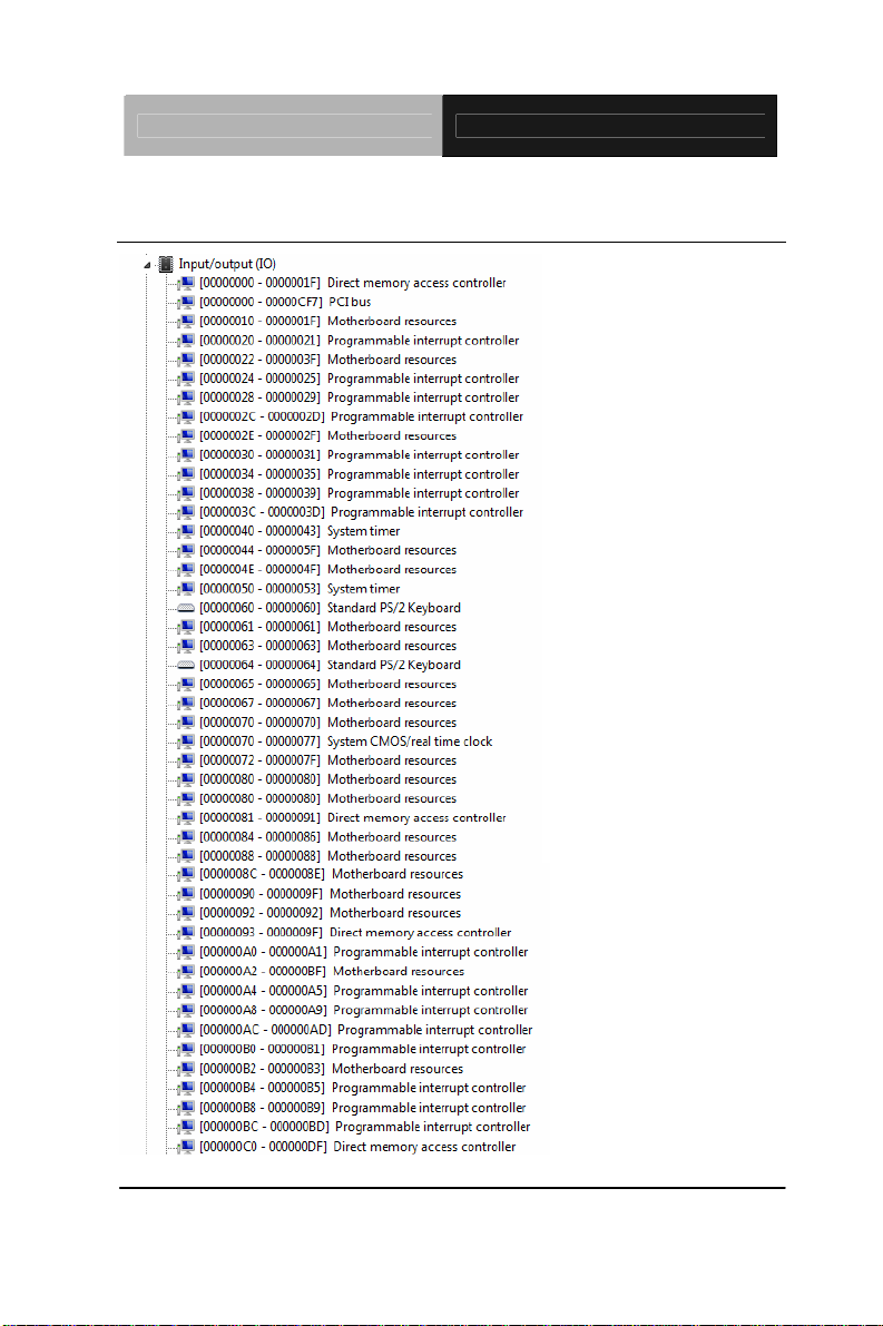
B.1 I/O Address Map
Appendix B I/O Information B - 2
Page 73

Touch Panel PC AHP-2176
Appendix B I/O Information B - 3
Page 74
Touch Panel PC AHP-2176
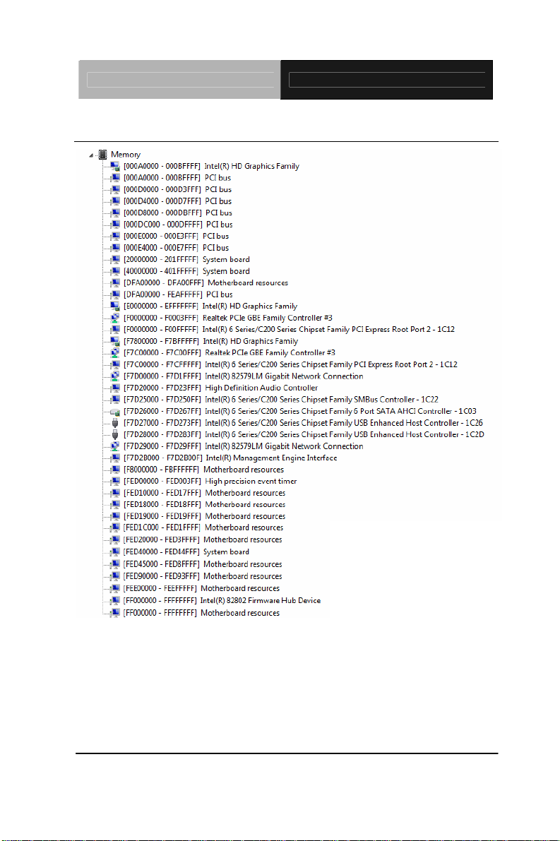
B.2 Memory Address Map
Appendix B I/O Information B - 4
Page 75
Touch Panel PC AHP-2176
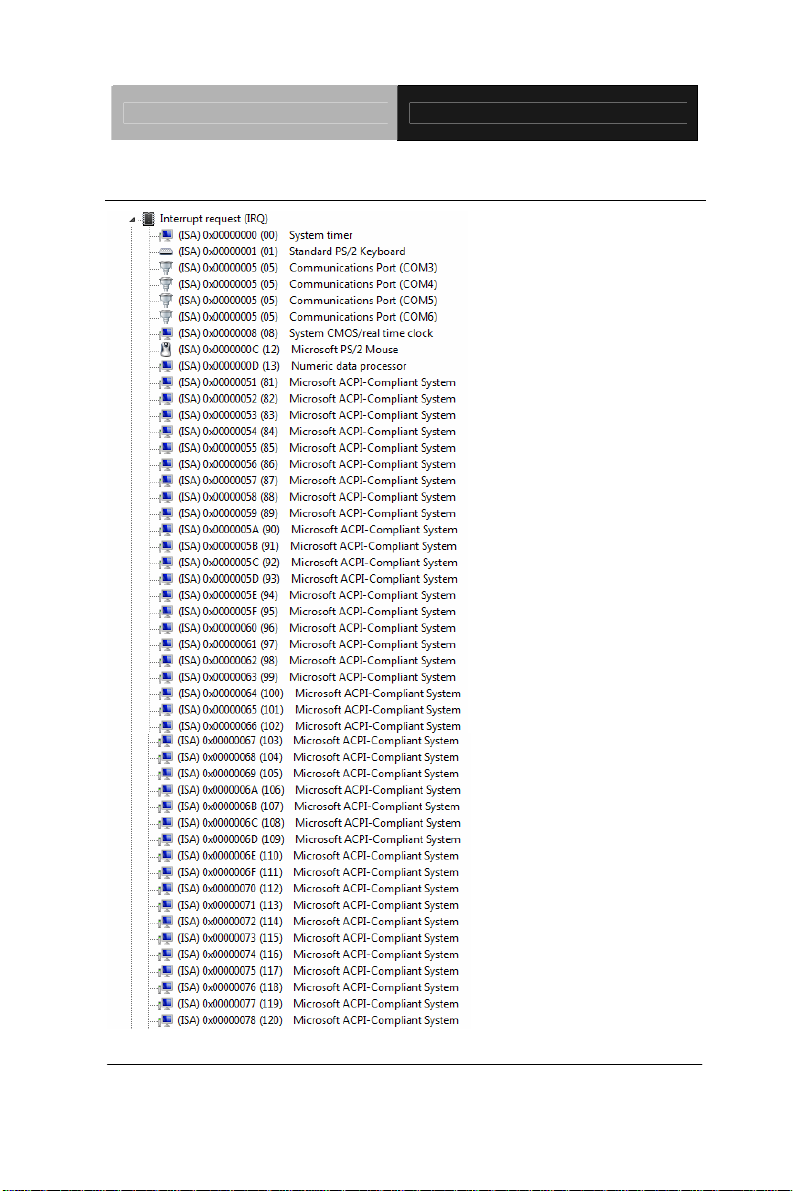
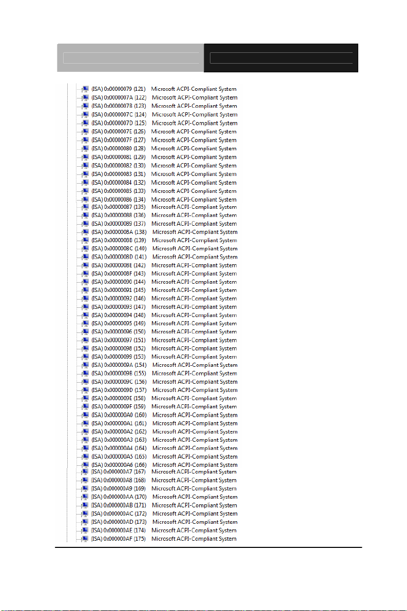
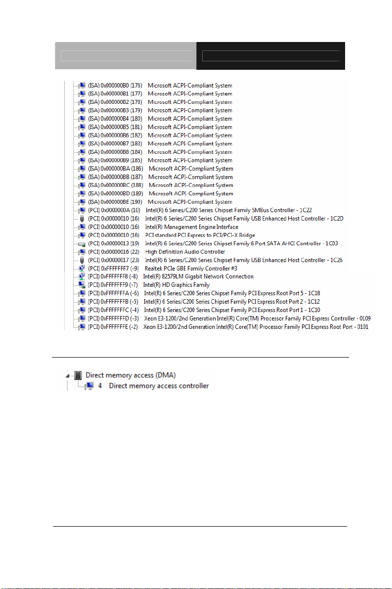
B.3 IRQ Mapping Chart
Appendix B I/O Information B - 5
Page 76
Touch Panel PC AHP-2176
Appendix B I/O Information B - 6
Page 77
Touch Panel PC AHP-2176
B.4 DMA Channel Assignments
Appendix B I/O Information B - 7
 Loading...