

Page 1

Touch Panel PC AHP-2122
Onboard Intel® Atom D525
AHP-2122 Manual 1st Ed.
AHP-2122
1.8 GHz Processor
Touch Panel PC
With 12.1” TFT LCD
December 2011
Page 2

Touch Panel PC AHP-2122
Copyright Notice
This document is copyrighted, 2011. All rights are reserved. The
original manufacturer reserves the right to make improvements to
the products described in this manual at any time without notice.
No part of this manual may be reproduced, copied, translated, or
transmitted in any form or by any means without the prior written
permission of the original manufacturer. Information provided in
this manual is intended to be accurate and reliable. However, the
original manufacturer assumes no responsibility for its use, or for
any infringements upon the rights of third parties that may result
from its use.
The material in this document is for product information only and is
subject to change without notice. While reasonable efforts have
been made in the preparation of this document to assure its
accuracy, AAEON assumes no liabilities resulting from errors or
omissions in this document, or from the use of the information
contained herein.
AAEON reserves the right to make changes in the product design
without notice to its users.
i
Page 3

Touch Panel PC AHP-2122
Acknowledgments
All other products’ name or trademarks are properties of their
respective owners.
AMI is a trademark of American Megatrends Inc.
Intel
Microsoft Windows
IBM, PC/AT, PS/2, and VGA are trademarks of International
All other product names or trademarks are properties of their
respective owners.
®
, and Atom™ are trademarks of Intel® Corporation.
®
is a registered trademark of Microsoft
Corp.
Business Machines Corporation.
ii
Page 4

Touch Panel PC AHP-2122
Packing List
Before you begin operating your PC, please make sure that the
following materials are enclosed:
AHP-2122 Touch Panel PC
Phoenix Terminal Block
Mounting brackets and screws
DVD-ROM for manual (in PDF format) and drivers
If any of these items should be missing or damaged, please contact
your distributor or sales representative immediately.
iii
Page 5

Touch Panel PC AHP-2122
Safety & Warranty
1. Read these safety instructions carefully.
2. Keep this user's manual for later reference.
3. Disconnect this equipment from any AC outlet before cleaning. Do
not use liquid or spray detergents for cleaning. Use a damp cl oth.
4. For pluggable equipment, the power outlet must be installed near
the equipment and must be easily accessible.
5. Keep this equipment away from humidity.
6. Put this equipment on a firm surface during installation. Dropping
it or letting it fall could cause damage.
7. The openings on the enclosure are for air convection. Protect the
equipment from overheating. DO NOT COVER THE OPENINGS.
8. Make sure the voltage of the power source is correct before
connecting the equipment to the power outlet.
9. Position the power cord so that people cannot step on it. Do not
place anything over the power cord.
10. All cautions and warnings on the equipment should be noted.
11. If the equipment is not used for a long time, disconnect it from the
power source to avoid damage by transient over-voltage.
12. Never pour any liquid into an opening. This could cause fire or
electrical shock.
13. Never open the equipment. For safety reasons, only qualified
service personnel should open the equipment.
14. If any of the following situations arises, get the equipment
checked by service personnel:
a. The power cord or plug is damaged.
b. Liquid has penetrated into the equipment.
c. The equipment has been exposed to moisture.
iv
Page 6

Touch Panel PC AHP-2122
d. The equipment does not work well, or you cannot get it
to work according to the user’s manual.
e. The equipment has been dropped and damaged.
f. The equipment has obvious signs of breakage.
15. DO NOT LEAVE THIS EQUIPMENT IN AN ENVIRONMENT
WHERE THE STORAGE TEMPERATURE IS BELOW -20°C
(-4°F) OR ABOVE 60°C (140°F). IT MAY DAMAGE THE
EQUIPMENT.
FCC
This device complies with Part 15 FCC Rules.
Operation is subject to the following two
conditions: (1) this device may not cause
harmful interference, and (2) this device must
accept any interference received including
interference that may cause undesired
operation.
Cau
tion:
There is a danger of explosion if the battery is incorrectly replaced.
Replace only with the same or equivalent type recommended by the
manufacturer. Dispose of used batteries according to the
manufacturer’s instructions and your local government’s recycling or
disposal directives.
v
Page 7
Touch Panel PC AHP-2122
Below Table for China RoHS Requirements
产品中有毒有害物质或元素名称及含量
AAEON Panel PC/ Workstation
有毒有害物质或元素
部件名称
印刷电路板
及其电子组件
外部信号
连接器及线材
外壳 × ○ ○ ○ ○ ○
中央处理器
与内存
硬盘 × ○ ○ ○ ○ ○
液晶模块 × ○ ○ ○ ○ ○
光驱 × ○ ○ ○ ○ ○
触控模块 × ○ ○ ○ ○ ○
电源 × ○ ○ ○ ○ ○
O:表示该有毒有害物质在该部件所有均质材料中的含量均在
SJ/T 11363-2006 标准规定的限量要求以下。
X:表示该有毒有害物质至少在该部件的某一均质材料中的含量超出
SJ/T 11363-2006 标准规定的限量要求。
备注:
一、此产品所标示之环保使用期限,系指在一般正常使用状况下。
二、上述部件物质中央处理器、内存、硬盘、光驱、触控模块为选购品。
铅
(Pb)汞 (Hg)镉 (Cd)
× ○ ○ ○ ○ ○
× ○ ○ ○ ○ ○
× ○ ○ ○ ○ ○
六价铬
(Cr(VI))
多溴联苯
(PBB)
多溴二苯醚
(PBDE)
vi
Page 8

Touch Panel PC AHP-2122
Contents
Chapter 1 General Information
1.1 Introduction................................................................ 1-2
1.2 Specification..............................................................1-3
1.3 Dimension ................................................................. 1-6
Chapter 2 Hardware Installation
2.1 Panelmount Installation.............................................2-2
2.2 COM 1/2 RS-232/422/485 Serial Port Connector.....2-4
2.3 CompactFlash™ Installation..................................... 2-5
2.4 Hard Disk Drive Installation.......................................2-6
Chapter 3 AMI BIOS Setup
3.1 System Test and Initialization ................................... 3-2
3.2 AMI BIOS Setup........................................................3-3
Chapter 4 Driver Installation
4.1 Introduction................................................................ 4-3
Appendix A AHCI Setting
A.1 WIN XP OS Installation..........................................A-2
vii
Page 9

Touch Panel PC AHP-2122
Chapter
1
General
Information
Chapter 1 General Information 1- 1
Page 10

Touch Panel PC AHP-2122
1.1 Introduction
The AHP-2122 operator panel is an Intel® Atom™ D525 1.8 GHz
processor computer that is designed to serve as a human machine
interface (HMI). It is a PC-based system with 12.1" color TFT LCD
display, onboard Ethernet controller, multi-COM port interfaces and
an audio controller. With a built-in CompactFlash socket, the
AHP-2122 is as compact and user friendly as a multi-function
computer. In addition, its "fit anywhere" design makes it very
flexible and able to be used in many different kinds of installations.
It can be VESA 100 wall mounted.
For system integrators, this simple, complete, compact and highly
integrated system let you easily build an operator panel into your
applications. Common industrial applications include factory
automation systems, precision machinery, and production process
control. It is also suitable for many non-industrial applications,
including vending machine, and car park automation. Our operator
panel is a reliable, cost-effective solution to your application's
processing requirements.
Chapter 1 General Information 1- 2
Page 11

Touch Panel PC AHP-2122
1.2 Specification
System
CPU Onboard Intel
Processor
System Memory DDR3 SODIMM x 1, Max. 4 GB
LCD / CRT Controller Integrated in Processor
I/O Port USB2.0 x 4
RS-232 x 1
RS-232/422/485 x 1
LAN x 2
VGA x 1
Line-out x 1
Storage Disk Drive CompactFlash™ slot x 1 (Internal);
2.5” SATA Hard Disk Drive x 1
OS Support Windows
®
Atom™ D525 1.8 GHz
®
XP, Windows® 7, Linux
Fedora, Windows® CE
Mechanical
Construction IP-65/NEMA4 for aluminum die cast
front bezel & iron chassis
Mounting Pane l/ Wall/ VESA 100/ Desktop
Dimension 13.6”(W) x 10.46”(H) x 3.58”(D)
(345.6mm x 265.7mm x 91mm)
Carton Dimension 17.9”(W) x 12.6”(H) x 15.75”(D) (455mm
Chapter 1 General Information 1-3
Page 12

Touch Panel PC AHP-2122
x 320mm x 400mm)
Net Weight 15.4 lb (7 kg)
Gross Weight 19.8 lb (9 kg)
Environmental
Operating T emperature -4
Storage Temperature -4
Operating Humidity 10% to 95%@ 40
Vibration 1 g rms/ 5-500Hz/ Operation—With
Shock 20 G peak acceleration (11 msec.
EMC CE/FCC Class A
Power Supply 9~30V DC input ;
o
F~140oF (-20oC~60oC)
o
F~158oF (-20oC~70oC)
o
C, non-condensing
Hard Disk Drive
duration)
Over-voltage protection
Low-voltage protection
Reverse protection
LCD
Display Type 12.1” TFT LCD
Max. Resolution 1024x768
Max. Colors 262K
Luminance (cd/m
Viewing Angle HTT: 160
Chapter 1 General Information 1- 4
2
) HTT : 500 cd/m2
STT : 1000 cd/m
o
(H),160o (V)
2
Page 13

Touch Panel PC AHP-2122
STT:160o (H),140o (V)
Backlight LED
Backlight MTBF (Hours) HTT : 50,000
STT : 60,000
Touch Screen
Type 5-wire analog resistive
Resolution 2048x2048
Light Transmission > 80%
Lifetime 35 million activations
Chapter 1 General Information 1-5
Page 14
Touch Panel PC AHP-2122
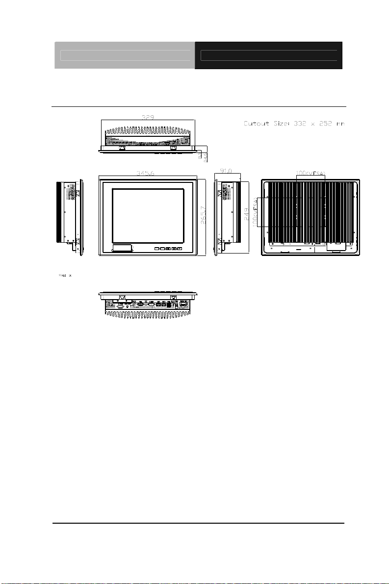
1.3 Dimension
Chapter 1 General Information 1- 6
Page 15

Touch Panel PC AHP-2122
Chapter
2
Hardware
Installation
Chapter 2 Quick Installation Guide 2-1
Page 16

Touch Panel PC AHP-2122
2.1 Panelmount Installation
The display panel can be mounted into the wall. You will need the
screws along with the mounting brackets, which be packed in the
accessory box. Follow the steps below:
Before you start to follow the instructions, please place the
display panel into the wall. See the following illustration on the
left.
Step 1: Place the mounting brackets and plug the screw.
Step 2: Aim the mounting set at the hole on the monitor.
Step 3: Move the mounting set to the narrow gauge and fix it with
screws.
Step 4: You’ve completed the preliminary when the mounting set
is tightened. Next, repeat the steps and tighten all mounting set
around the monitor until the monitor is firmly mounting on the
wall.
Chapter 2 Quick Installation Guide 2 - 2
Page 17

Touch Panel PC AHP-2122
1 2 3 4
Complete Illustration
Chapter 2 Quick Installation Guide
2 - 3
Page 18

Touch Panel PC AHP-2122
2.2 COM1/2 RS-232/422/485 Serial Port Connector
COM1 (D-sub 9 male)
2
1
4
5
6
7
Pin 2BSignal Pin 3BSignal
1 DCD 2 RXD
3 TXD 4 DTR
5 GND 6 DSR
7 RTS 8 CTS
9 RI
COM2 RS-232/422/485 (D-sub 9 male)
2
1
6
7
Pin Signal Pin Signal
1
3
DCD
(422TXD-/485DATA-)
TXD
(422TXD+/485DATA+)
2 RXD (422RXD+)
4 DTR (422RXD-)
5 GND 6 DSR
7 RTS 8 CTS
9 RI/+5Volt/+12Volt
9
8
4
5
9
8
Chapter 2 Quick Installation Guide 2 - 4
Page 19

Touch Panel PC AHP-2122
2.3 Hard Disk Drive Installation
Step 1: Unfasten the screws of the heatsink
Step 2: Get the Bracket of Hard Disk Drive and Thermal Pad from the
package
Chapter 2 Quick Installation Guide
2 - 5
Page 20

Touch Panel PC AHP-2122
Step 3: Stick the Thermal Pad onto the Hard Disk Drive and fasten the
Hard Disk Drive onto the bracket
Step 4: Fasten the screws of the hard disk bracket onto the AHP-2122
Chapter 2 Quick Installation Guide 2 - 6
Page 21

Touch Panel PC AHP-2122
2.4 Wireless Module Installation
Follow the connecting locations of each cable showed on the picture below
to install the Wireless Module.
Chapter 2 Quick Installation Guide
2 - 7
Page 22

Touch Panel PC AHP-2122
Chapter
3
AMI
BIOS Setup
Chapter 3 AMI BIOS Setup 3-1
Page 23

Touch Panel PC AHP-2122
3.1 System Test and Initialization
These routines test and initialize board hardware. If the routines
encounter an error during the tests, you will either hear a few short
beeps or see an error message on the screen. There are two kinds
of errors: fatal and non-fatal. The system can usually continue the
boot up sequence with non-fatal errors.
System configuration verification
These routines check the current system configuration against the
values stored in the CMOS memory. If they do not match, the
program outputs an error message. You will then need to run the
BIOS setup program to set the configuration information in memory.
There are three situations in which you will need to change the
CMOS settings:
1. You are starting your system for the first time
2. You have changed the hardware attached to your system
3. The CMOS memory has lost power and the configuration
information has been erased.
The AHP-2122 CMOS memory has an integral lithium battery
backup for data retention. However, you will need to replace the
complete unit when it finally runs down.
Chapter 3 AMI BIOS Setup 3-2
Page 24

Touch Panel PC AHP-2122
3.2 AMI BIOS Setup
AMI BIOS ROM has a built-in Setup program that allows users to
modify the basic system configuration. This type of information is
stored in battery-backed CMOS RAM so that it retains the Setup
information when the power is turned off.
Entering Setup
Power on the computer and press <Del> or <F2> immediately. This
will allow you to enter Setup.
Main
Set the date, use tab to switch between date elements.
Advanced
Enable disable boot option for legacy network devices.
Chipset
Host bridge parameters.
Boot
Enables/disable quiet boot option.
Security
Set setup administrator password.
Save&Exit
Exit system setup after saving the changes.
Chapter 3 AMI BIOS Setup 3-3
Page 25

Touch Panel PC AHP-2122
Chapter
4
Driver
Inst
allation
Chapter 4 Driver Installation 4 - 1
Page 26

Touch Panel PC AHP-2122
The AHP-2122 comes with a DVD-ROM that contains all
drivers and utilities that meet your needs.
Follow the sequence below to install the drivers:
Step 1 – Install Chipset Driver
Step 2 – Install VGA Driver
Step 3 – Install Audio Driver
Step 4 – Install LAN Driver
Step 5 – Install Touch Panel Driver
Step 6 – Install AHCI Driver
Step 7 – Install TPM Driver
Step 8 – Install Wireless Driver (Optional)
Please read instructions below for further detailed
installations.
Chapter 4 Driver Installation 4 - 2
Page 27

Touch Panel PC AHP-2122
4.1 Installation:
Insert the AHP-2122 DVD-ROM into the DVD-ROM Drive. And
install the drivers from Step 1 to Step 8 in order.
Step 1 – Install Chipset Driver
1. Click on the STEP1-CHIPSET and select the OS folder
your system is
2. Double click on the infinst_autol.exe located in each OS
folder
3. Follow the instructions that the window shows
4. The system will help you install the driver automatically
Step 2 – Install VGA Driver
1. Click on the STEP2-VGA folder and select the OS folder
your system is
2. Double click on the Setup.exe located in each OS folder
3. Follow the instructions that the window shows
4. The system will help you install the driver automatically
Step 3 – Install Audio Driver
1. Click on the STEP3-AUDIO folder and select the OS
folder your system is
2. Double click on the Setup.exe located in each OS folder
3. Follow the instructions that the window shows
4. The system will help you install the driver automatically
Chapter 4 Driver Installation 4 - 3
Page 28

Touch Panel PC AHP-2122
Step 4 – Install LAN Driver
1. Click on the STEP4-LAN folder and select the OS folder
your system is
2. Double click on the .exe located in each OS folder
3. Follow the instructions that the window shows
4. The system will help you install the driver automatically
Step 5 – Install Touch Panel Driver
1. Click on the STEP5-TOUCHPANEL folder and select the
OS folder your system is
2. Double click on the setup.exe located in each OS folder
3. Follow the instructions that the window shows
4. The system will help you install the driver automatically
Step 6 – Install AHCI Driver
Please refer to Appendix A AHCI Setting
Step 7 – Install TPM Driver
1. Click on the STEP7-TPM folder and select the OS folder
your system is
2. Double click on the Setup.exe located in each OS folder
3. Follow the instructions that the window shows
4. The system will help you install the driver automatically
Chapter 4 Driver Installation 4 - 4
Page 29

Touch Panel PC AHP-2122
Step 8 – Install Wireless Driver (Optional)
1. Click on the STEP8-Wireless (option) folder and select
the OS folder your system is.
2. Double click on the .exe located in each OS folder
3. Follow the instructions that the window shows
4. The system will help you install the driver automatically
Chapter 4 Driver Installation 4 - 5
Page 30

Touch Panel PC AHP-2122
A
Appendix
AHCI Setting
Appendix A AHCI Setting A-1
Page 31

Touch Panel PC AHP-2122
A.1 WIN XP OS installation
Step 1: Copy the files below from “Driver CD” -> STEP6-AHCI
Driver\WINXP_32” T o Disk
Step 2: Connect the USB floppy (disk with AHCI files) to the AHP-2122
Appendix A AHCI Setting A-2
Page 32

Touch Panel PC AHP-2122
Step 3: Setup OS
Step 4: Press “F6”
Appendix A AHCI Setting A-3
Page 33

Touch Panel PC AHP-2122
Step 5: Choose “S”
Step 6: Choose “Intel(R) ICH8M-E/M SATA AHCI Controller”
Appendix A AHCI Setting A-4
Page 34

Touch Panel PC AHP-2122
Step 7: It will show the model number you select and then press “ENTER”
Step 8: Setup is starting Windows
Appendix A AHCI Setting A-5
 Loading...