

Page 1

Touch Panel PC AHP-1083
Intel® Atom™ D2550
1.86 GHz Processor
With 8.4” TFT LCD
AHP-1083 Manual 2
AHP-1083
Touch Panel PC
nd
Ed.
July 2013
Page 2

Touch Panel PC AHP-1083
Copyright Notice
This document is copyrighted, 2013. All rights are reserved. The
original manufacturer reserves the right to make improvements to
the products described in this manual at any time without notice.
No part of this manual may be reproduced, copied, translated, or
transmitted in any form or by any means without the prior written
permission of the original manufacturer. Information provided in
this manual is intended to be accurate and reliable. However, the
original manufacturer assumes no responsibility for its use, or for
any infringements upon the rights of third parties that may result
from its use.
The material in this document is for product information only and is
subject to change without notice. While reasonable efforts have
been made in the preparation of this document to assure its
accuracy, AAEON assumes no liabilities resulting from errors or
omissions in this document, or from the use of the information
contained herein.
AAEON reserves the right to make changes in the product design
without notice to its users.
i
Page 3

Touch Panel PC AHP-1083
Acknowledgments
All other products’ name or trademarks are properties of their
respective owners.
Award is a trademark of Award Software International, Inc.
Intel
Microsoft Windows
IBM, PC/AT, PS/2, and VGA are trademarks of International
All other product names or trademarks are properties of their
respective owners.
®
, and Atom™ are trademarks of Intel® Corporation.
®
is a registered trademark of Microsoft
Corp.
Business Machines Corporation.
ii
Page 4

Touch Panel PC AHP-1083
Packing List
Before you begin operating your PC, please make sure that the
following materials are enclosed:
1 AHP-1083 Touch Panel PC
1 Phoenix Terminal Block
1 Mounting bracket and screws
1 CD-ROM for manual (in PDF format)
If any of these items should be missing or damaged, please contact
your distributor or sales representative immediately.
iii
Page 5

Touch Panel PC AHP-1083
Safety & Warranty
1. Read these safety instructions carefully.
2. Keep this user's manual for later reference.
3. Disconnect this equipment from any AC outlet before cleaning. Do
not use liquid or spray detergents for cleaning. Use a damp cl oth.
4. For pluggable equipment, the power outlet must be installed near
the equipment and must be easily accessible.
5. Keep this equipment away from humidity.
6. Put this equipment on a firm surface during installation. Dropping
it or letting it fall could cause damage.
7. The openings on the enclosure are for air convection. Protect the
equipment from overheating. DO NOT COVER THE OPENINGS.
8. Make sure the voltage of the power source is correct before
connecting the equipment to the power outlet.
9. Position the power cord so that people cannot step on it. Do not
place anything over the power cord.
10. All cautions and warnings on the equipment should be noted.
11. If the equipment is not used for a long time, disconnect it from the
power source to avoid damage by transient over-voltage.
12. Never pour any liquid into an opening. This could cause fire or
electrical shock.
13. Never open the equipment. For safety reasons, only qualified
service personnel should open the equipment.
14. If any of the following situations arises, get the equipment
checked by service personnel:
a. The power cord or plug is damaged.
b. Liquid has penetrated into the equipment.
c. The equipment has been exposed to moisture.
iv
Page 6

Touch Panel PC AHP-1083
d. The equipment does not work well, or you cannot get it
to work according to the user’s manual.
e. The equipment has been dropped and damaged.
f. The equipment has obvious signs of breakage.
15. DO NOT LEAVE THIS EQUIPMENT IN AN ENVIRONMENT
WHERE THE STORAGE TEMPERATURE IS BELOW -20°C
(-4°F) OR ABOVE 60°C (140°F). IT MAY DAMAGE THE
EQUIPMENT.
FCC
This device complies with Part 15 FCC Rules.
Operation is subject to the following two
conditions: (1) this device may not cause
harmful interference, and (2) this device must
accept any interference received including
interference that may cause undesired
operation.
Cau
tion:
There is a danger of explosion if the battery is incorrectly replaced.
Replace only with the same or equivalent type recommended by the
manufacturer. Dispose of used batteries according to the
manufacturer’s instructions and your local government’s recycling or
disposal directives.
v
Page 7

Touch Panel PC AHP-1083
Below Table for China RoHS Requirements
产品中有毒有害物质或元素名称及含量
AAEON Panel PC/ Workstation
有毒有害物质或元素
部件名称
印刷电路板
及其电子组件
外部信号
连接器及线材
外壳 × ○ ○ ○ ○ ○
中央处理器
与内存
硬盘 × ○ ○ ○ ○ ○
液晶模块 × ○ ○ ○ ○ ○
光驱 × ○ ○ ○ ○ ○
触控模块 × ○ ○ ○ ○ ○
电源 × ○ ○ ○ ○ ○
O:表示该有毒有害物质在该部件所有均质材料中的含量均在
SJ/T 11363-2006 标准规定的限量要求以下。
X:表示该有毒有害物质至少在该部件的某一均质材料中的含量超出
SJ/T 11363-2006 标准规定的限量要求。
备注:
一、此产品所标示之环保使用期限,系指在一般正常使用状况下。
二、上述部件物质中央处理器、内存、硬盘、光驱、触控模块为选购品。
铅
(Pb)汞 (Hg)镉 (Cd)
× ○ ○ ○ ○ ○
× ○ ○ ○ ○ ○
× ○ ○ ○ ○ ○
六价铬
(Cr(VI))
多溴联苯
(PBB)
多溴二苯醚
(PBDE)
vi
Page 8

Touch Panel PC AHP-1083
Contents
Chapter 1 General Information
1.1 Introduction................................................................ 1-2
1.2 Specification..............................................................1-3
1.3 Dimension ................................................................. 1-6
Chapter 2 Hardware Installation
2.1 Panelmount Installation.............................................2-2
2.2 Clear CMOS (JP2) .................................................... 2-3
2.3 COM2 RI/+5V/+12V Selection (JP3).........................2-3
2.4 COM Port #2 (CN19)................................................. 2-3
2.5 COM Port #1 (CN33)................................................. 2-4
2.6 CompactFlash™ Installation..................................... 2-5
2.7 Hard Disk Drive Installation.......................................2-6
Chapter 3 AMI BIOS Setup
3.1 Setup Menu...............................................................2-2
Chapter 4 Driver Installation
4.1 Installation.................................................................4-3
vii
Page 9

Touch Panel PC AHP-1083
Chapter
1
General
Information
Chapter 1 General Information 1- 1
Page 10

Touch Panel PC AHP-1083
1.1 Introduction
The AHP-1083 operator panel is an Intel® Atom™ D2550 1.86 GHz
processor computer that is designed to serve as a human machine
interface (HMI). It is a PC-based system with 8.4" color TFT LCD
display, onboard Ethernet controller, multi-COM port interfaces and
an audio controller. With a built-in CFast socket, the AHP-1083 is
as compact and user friendly as a multi-function computer. In
addition, its "fit anywhere" design makes it very flexible and able to
be used in many different kinds of installations. It can be VESA 75
mounted or Panel mounted.
For system integrators, this simple, complete, compact and highly
integrated system let you easily build an operator panel into your
applications. Common industrial applications include factory
automation systems, precision machinery, and production process
control. It is also suitable for many non-industrial applications,
including vending machine, and car park automation. Our operator
panel is a reliable, cost-effective solution to your application's
processing requirements.
Chapter 1 General Information 1- 2
Page 11

Touch Panel PC AHP-1083
1.2 Specification
System
CPU Onboard Intel
Processor
System Memory 204pin DDRIII 800/1066 SODIMM x 1,
Max. 4GB, default 2GB
LCD / CRT Controller Intel
I/O Port USB2.0 x 2
®
NM10 Integrated
RS-232 x 1
RS-232/422/485 x 1
LAN x 2
VGA x 1
Power input x 1
Power button x 1
®
Atom™ D2550 1.86 GHz
Storage Disk Drive CFast™ slot x 1 (Easy to swap);
2.5” SATA HDD bay x 1 (Anti-vibration
1G)
Expansion Mini card x 1
OS Support Windows CE 6.0, Windows XP Pro,
Windows XP Embedded, Windows 7,
Windows Embedded Standard 7, Linux
Kernel 2.6.3 or above
Chapter 1 General Information 1-3
Page 12

Touch Panel PC AHP-1083
Mechanical
Construction Plastic front bezel and aluminum back
chassis
Mounting Panel/ VESA
Dimension 16"(W) x 12.2"(H) x 2.67"(D)
(407mm x 310.5mm x 67.9mm)
Carton Size 20.67"(W) x 18.31"(H) x 9.1"(D)
(4525mm x 465mm x 230mm)
Net Weight 4.4 lb (2kg)
Gross Weight 6.16 lb (2.8kg)
Environmental
Operating T emperature 32°F ~ 122°F (0°C ~50°C)
Storage Temperature -4°F~158°F (-20°C~70°C)
Operating Humidity 5 to 90%@ 40°C, non-condensing
Vibration 1 Grms / 5~ 500Hz / operation – With
HDD
3 Grms / 5~ 500Hz / operation – With
CFast
Shock 20 G peak acceleration (11 msec.
duration) – With HDD
EMC CE/FCC Class A
Power Supply DC 12V (Phoenix) (ATX Mode)
Chapter 1 General Information 1- 4
Page 13

Touch Panel PC AHP-1083
LCD
Display Type 8.4”, SVGA, 450 nits, LED backlight
Max. Resolution 800x600
Max. Colors 262k
Power Consumption 7.44W
Response Time (msec) 10
Interface Single channel LVDS
Luminance (cd/m
Contrast Ratio 600:1
Viewing Angle 80° (H) x 70° (V)
Backlight MTBF (Hours) 50,000
2
) 450 nits
Touch Screen
Type 5-wire analog touch panel
Light Transmission > 80%
Lifetime 35 million activations
Chapter 1 General Information 1-5
Page 14
Touch Panel PC AHP-1083
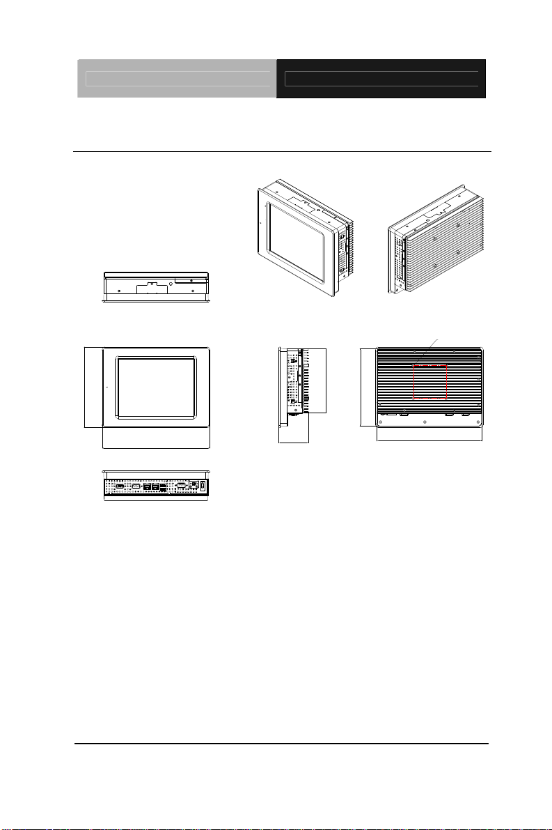
1.3 Dimension
AHP-1083
UNITS:mm
VESA 75
183.0
245.0
Chapter 1 General Information 1- 6
67.9
175.9
146.0
237.9
Page 15

Touch Panel PC AHP-1083
Chapter
2
Hardware
Inst
Chapter 2 Quick Installation Guide 2-1
allation
Page 16
Touch Panel PC AHP-1083
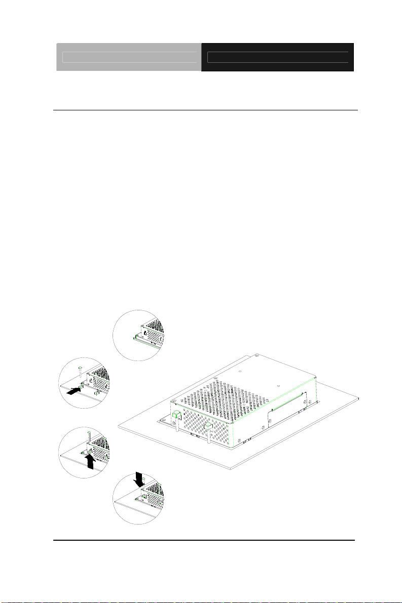
2.1 Panelmount Installation
The display panel can be mounted into the wall. You will need the
screws along with the mounting brackets, which be packed in the
accessory box. Follow the steps below:
Step 1: Place the operator panel into the wall.
Step 2: Place the mounting brackets and bore the screw on it.
Step 3: Screw mounting kits to fix the operator panel.
Step 4: When the mounting set has b een tightened, repeat the
Steps ab ove and tighten all mounting sets around the
monitor until the monitor has been firmly mounted to
the wall.
Chapter 2 Quick Installation Guide 2 - 2
Page 17
Touch Panel PC AHP-1083
2.2 Clear CMOS (JP2)
JP2 Function
1-2 Normal (Default)
2-3 Clear CMOS
2.3 COM2 RI/+5V/+12V Selection (JP3)
JP3 Function
1-2 +12V
3-4 RI (Default)
5-6 +5V
Note: Max. Current rating is 0.5A.
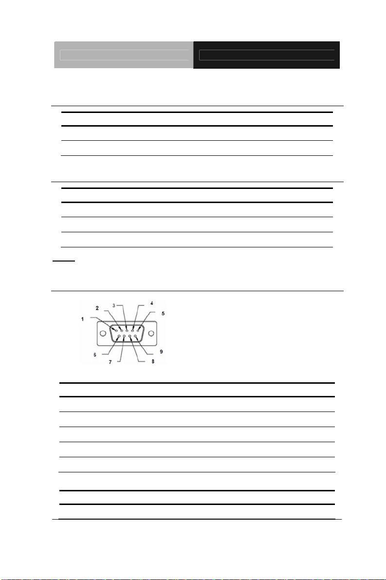
2.4 COM Port #2 (CN19)
RS-232 Mode
Pin Signal Pin Signal
1 DCDB 2 DSRB
3 RXB 4 RTSB
5 TXB 6 CTSB
7 DTRB 8 RIB / +5 Volt. / (+12 Volt.)
9 Ground 10 N/C
RS-422 Mode
Pin Signal Pin Signal
1 TXD- 2 N/C
Chapter 2 Quick Installation Guide
2 - 3
Page 18

Touch Panel PC AHP-1083
3 RXD+ 4 N/C
5 TXD+ 6 N/C
7 RXD- 8 N/C / +5 Volt. / (+12 Volt.)
9 Ground 10 N/C
RS-485 Mode
Pin Signal Pin Signal
1 TXD- 2 N/C
3 N/C 4 N/C
5 TXD+ 6 N/C
7 N/C 8 N/C / +5 Volt. / (+12 Volt.)
9 Ground 10 N/C
43 CRT_PLUG#
2.5 COM Port #1 (CN33)
Pin Signal Pin Signal
1 DCDA 2 RXA
3 TXA 4 DTRA
5 Ground 6 DSRA
7 RTSA 8 CTSA
9 RIA
Chapter 2 Quick Installation Guide 2 - 4
Page 19

Touch Panel PC AHP-1083
2.6 CompactFlash™ Installation
Step 1: Loose the screw of cover to open the CompactFlash™ Slot
Step 2: Insert the CompactFlash™ to the CompactFlash™ slot
Chapter 2 Quick Installation Guide
2 - 5
Page 20

Touch Panel PC AHP-1083
2.7 Hard Disk Drive Installation
Step 1: Loose the eight M3 screws of the rear cover.
Step 2: Loose the three specified M3 screws to get the Hard Disk Drive
(HDD) bracket.
Chapter 2 Quick Installation Guide 2 - 6
Page 21

Touch Panel PC AHP-1083
Step 3: Insert the HDD to the HDD bracket
Step 4: Fasten the four screws to fasten the HDD and the HDD bracket
Chapter 2 Quick Installation Guide
2 - 7
Page 22
Touch Panel PC AHP-1083
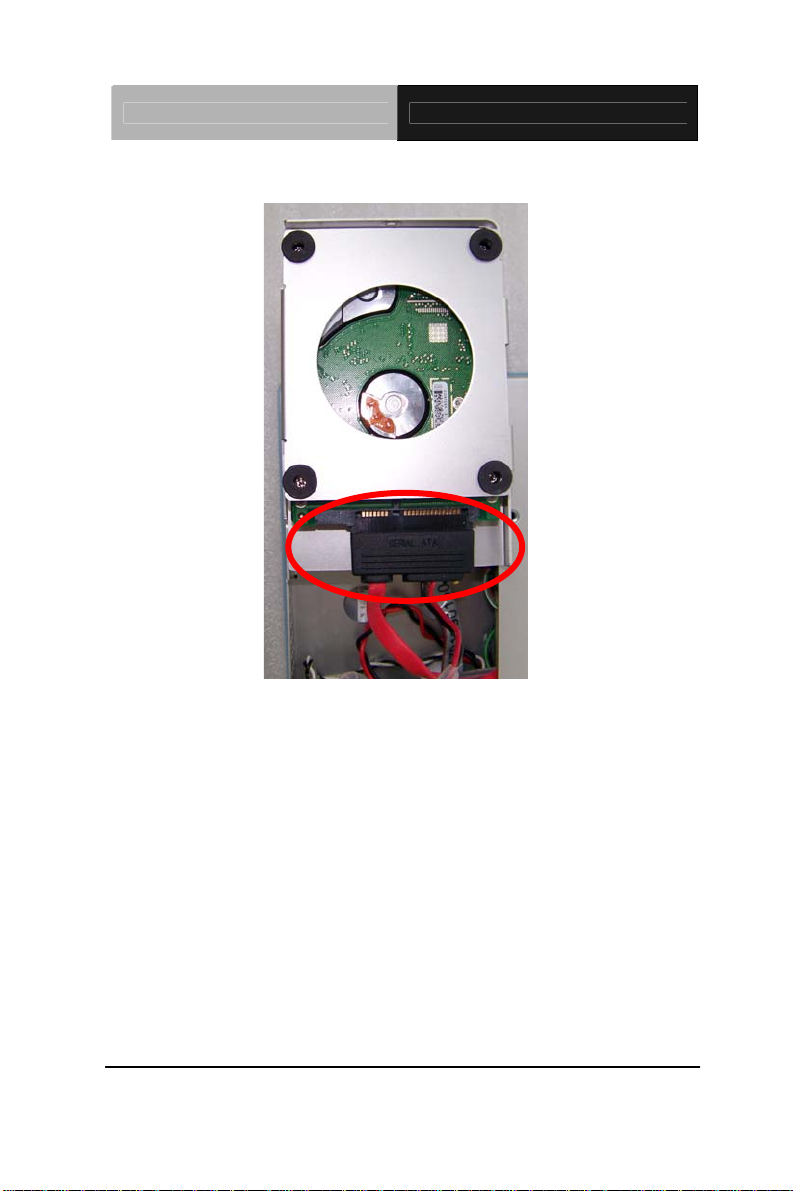
Step 5: Connect the SATA cable to the HDD
Chapter 2 Quick Installation Guide 2 - 8
Page 23

Touch Panel PC AHP-1083
Chapter
3
AMI
BIOS Setup
Chapter 3 AMI BIOS Setup 3-1
Page 24

Touch Panel PC AHP-1083
3.1 Setup Menu
Setup submenu: Main
Options summary: (default setting)
System Date Day MM:DD:YYYY
Change the month, year and century. The ‘Day’ is changed automatically.
System Time HH : MM : SS
Change the clock of the system.
Chapter 3 AMI BIOS Setup 3-2
Page 25

Touch Panel PC AHP-1083
Setup submenu: Advanced
Options summary: (default setting)
ACPI Settings
System ACPI Parameters
S5 RTC Wake Settings
Support S5 RTC Wake Function
CPU Configuration
CPU Configuration Parameters
SATA Configuration
SATA Device Options Settings
USB Configuration
Chapter 3 AMI BIOS Setup 3-3
Page 26
Touch Panel PC AHP-1083
USB Configuration Parameters
Super IO Configuration
IT8783 Super IO Configuration Parameters
H/W Monitor
Monitor hardware status
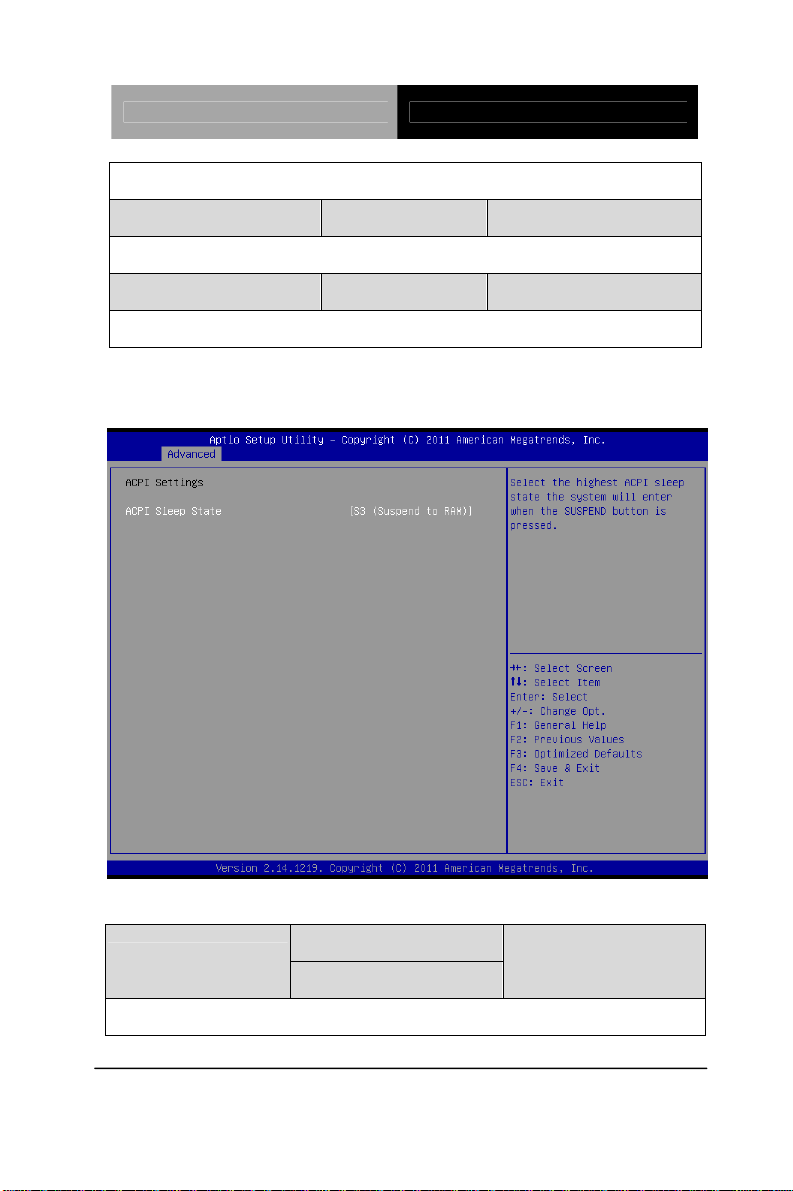
ACPI Settings
Options summary: (default setting)
Suspend Disabled
ACPI Sleep State
S3 (Suspend to RAM)
Select the ACPI state used for System Suspend
Chapter 3 AMI BIOS Setup 3-4
Page 27

Touch Panel PC AHP-1083
S5 RTC Wake Settings
Options summary: (default setting)
Wake system with Fixed
Time
Enable or disable System wake on alarm event. Wake up time is setting by following
settings.
Wake up day 0-31
Select 0 for daily system wake up 1-31 for which day of the month that you would
like the system to wake up
Wake up hour 0-23
Disabled
Enabled
Chapter 3 AMI BIOS Setup 3-5
Page 28

Touch Panel PC AHP-1083
Wake up minute 0-59
Wake up second 0-59
Wake system with
Dynamic Time
Enable or disable System wake on alarm event. Wake up time is current time +
Increase minutes.
Wake up minute increase 1-5
Disabled
Enabled
CPU Configuration
Chapter 3 AMI BIOS Setup 3-6
Page 29

Touch Panel PC AHP-1083
Options summary: (default setting)
Disabled Hyper-Threading
Enabled
CPU Hyper-Threading Technology support or not
SATA Configuration
Options summary: (default setting)
SATA Controller(s)
SATA Controller Enable/Disable
SATA Mode
Enabled
Disabled
IDE
Chapter 3 AMI BIOS Setup 3-7
Page 30
Touch Panel PC AHP-1083
AHCI
Configure SATA controller operating as IDE/AHCI mode.
SATA PORTx
Enable / Disable SATA Portx
SATA Portx Hot Plug
Enable / Disable SATA Portx Hot Plug function
Enabled
Disabled
Enabled
Disabled
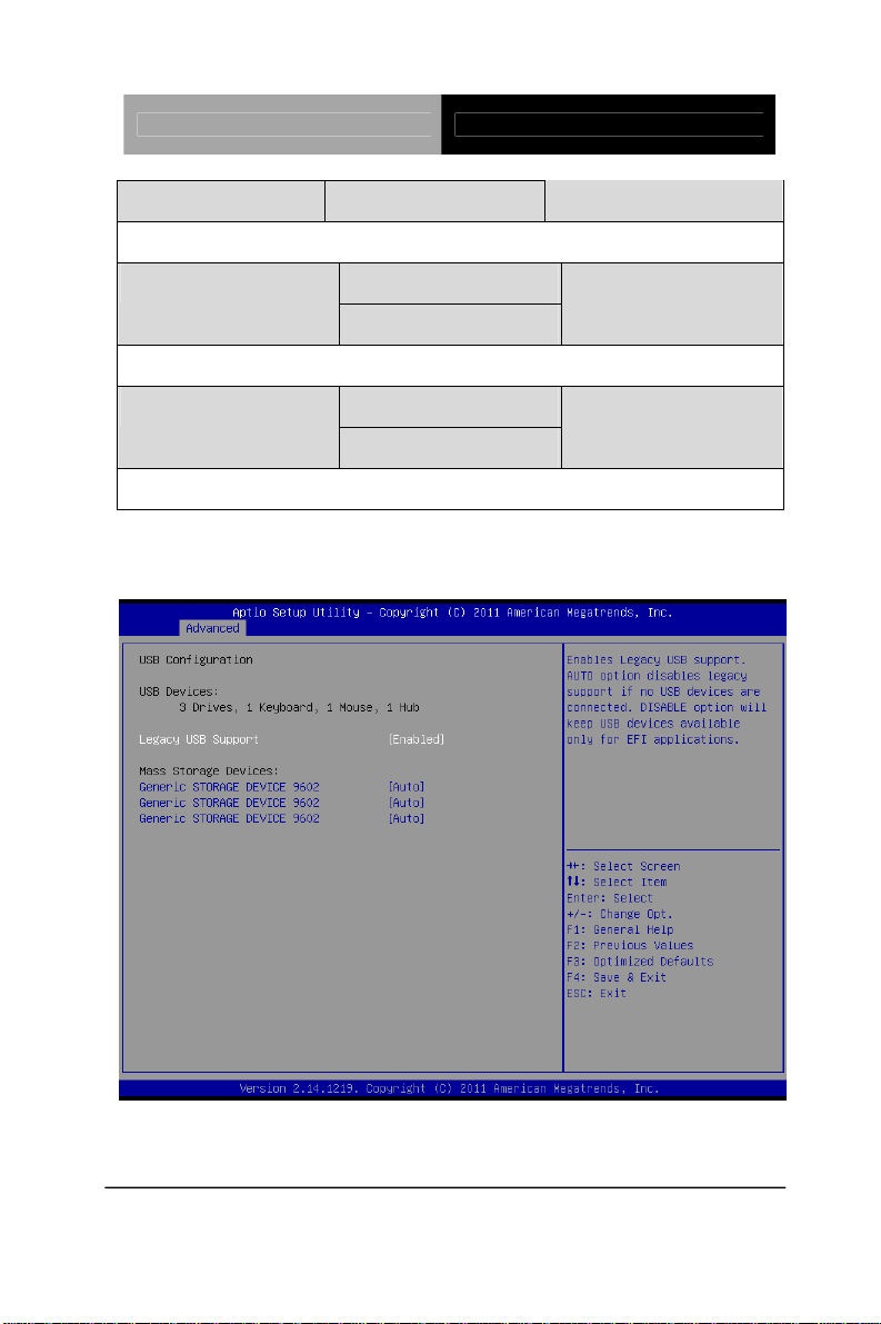
USB Configuration
Chapter 3 AMI BIOS Setup 3-8
Page 31

Touch Panel PC AHP-1083
Options summary: (default setting)
Legacy USB Support
Enables BIOS Support for Legacy USB Support. When enabled, USB can be
functional in legacy environment like DOS. AUTO option disables legacy support if
no USB devices are connected. DISABLE option will keep USB devices available
only for EFI application
(Emulation Type)
If Auto. USB devices less than 530MB will be emulated as Floppy and remaining as
Floppy and remaining as hard drive. Forced FDD option can be used to force a
HDD formatted drive to boot as FDD(Ex. ZIP drive)
Enabled
Disabled
Auto
Auto
Floppy
Forced FDD
Hard Disk
CD-ROM
Device Name
Chapter 3 AMI BIOS Setup 3-9
Page 32

Touch Panel PC AHP-1083
Super IO Configuration
Options summary: (default setting)
Serial Port x Configuration
Set Parameters of Serial Port x
Restore AC Power Loss
Set Power on after power fail function
Power off
Power on
Last State
Chapter 3 AMI BIOS Setup 3-10
Page 33

Touch Panel PC AHP-1083
Serial Port 2 Configuration
Options summary: (default setting)
Disabled Serial Port
Enabled
En/Disable specified serial port.
Change Settings
Auto
IO=2F8h; IRQ=3;
IO=3F8h; IRQ=3,4,5,7,10,11,12;
IO=2F8h; IRQ=3,4,5,7,10,11,12;
IO=3E8h; IRQ=3,4,5,7,10,11,12;
IO=2E8h; IRQ=3,4,5,7,10,11,12;
Chapter 3 AMI BIOS Setup 3-11
Page 34

Touch Panel PC AHP-1083
Select a resource setting for Super IO device.
COM2 Type Option
Configure COM2 operated as RS232, RS422 or RS485.
RS232
RS422
RS485
H/W Monitor
Chapter 3 AMI BIOS Setup 3-12
Page 35

Touch Panel PC AHP-1083
Setup submenu: Chipset
Options summary: (default setting)
Host Bridge
Host Bridge Parameters
South Bridge
South Bridge Parameters
Chapter 3 AMI BIOS Setup 3-13
Page 36

Touch Panel PC AHP-1083
Host Bridge
Options summary: (default setting)
Intel IGD Configuration
Enter to set Graphic Configuration
Memory Information
Show current memory information
Chapter 3 AMI BIOS Setup 3-14
Page 37

Touch Panel PC AHP-1083
Intel IGD Configuration
Options summary: (default setting)
Disabled Auto Disable IGD
Enabled
Auto disable IGD upon external GFX detected.
IGFX – Boot Type
Select the Video Device which will be activated during POST
LCD Panel Type
Select 1st panel native resolution.
VBIOS Default
CRT
1st LVDS
800x600 18bit
Chapter 3 AMI BIOS Setup 3-15
Page 38
Touch Panel PC AHP-1083
PWM Inverted LVDS1 Backlight Control
PWM Normal
Backlight control setting
LVDSx Backlight
Controller
Adjust backlight brightness
Dis/Enable LVDSx
Size
Configure Fixed Graphics Memory Size
100%
75%
50%
25%
0%
Disabled Control LVDSx
Enabled
128MB Fixed Graphics Memory
256MB
Chapter 3 AMI BIOS Setup 3-16
Page 39

Touch Panel PC AHP-1083
South Bridge
Options summary: (default setting)
Power Mode
Select AT/ATX Power Mode
TPT Devices
Configure onboard TPT Devices
Enable/Disable PCI Express Port 0 - 3
ATX Type
AT Type
Disabled PCI Express Port x
Enabled
Chapter 3 AMI BIOS Setup 3-17
Page 40

Touch Panel PC AHP-1083
TPT Devices
Options summary: (default setting)
R8111E Enable/Disable
Disabled R8111E #x Controller
Enabld
Chapter 3 AMI BIOS Setup 3-18
Page 41

Touch Panel PC AHP-1083
Boot Configuration
Options summary: (default setting)
Disabled Quiet Boot
Enabled
Enables or disables Quiet Boot option
Disabled
OpROM
En/Disable PXE boot for onboard 8111E LAN
Boot Option #X
XXXX Drive BBS Priorities
The order of boot priorities.
Enabled
Launch 8111E PXE
Chapter 3 AMI BIOS Setup 3-19
Page 42
Touch Panel PC AHP-1083
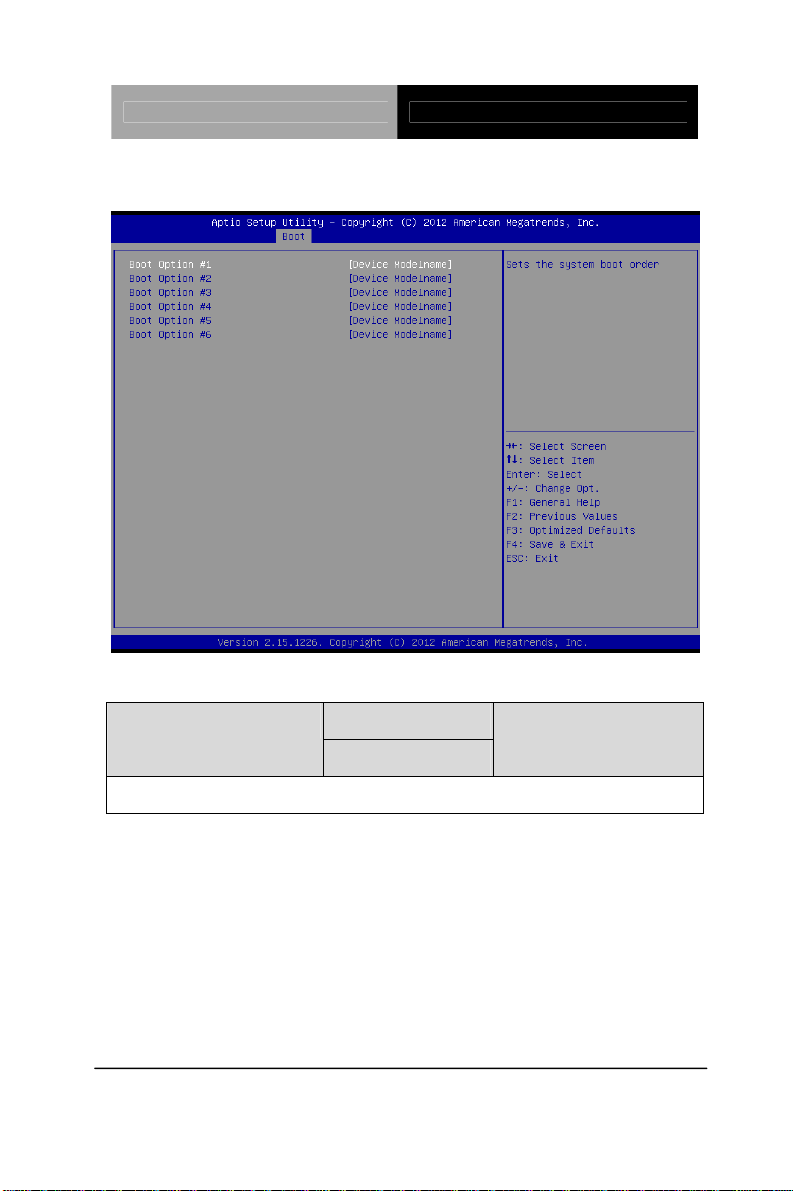
BBS Priorities
Options summary: (default setting)
Sets the system boot order
Disabled Boot Option #x
Device name
Chapter 3 AMI BIOS Setup 3-20
Page 43

Touch Panel PC AHP-1083
Setup submenu: Security
Options summary: (default setting)
Not set
User Password
You can install a Supervisor password, and if you install a supervisor password, you
can then install a user password. A user password does not provide access to many
of the features in the Setup utility.
Install the Password:
Press Enter on this item, a dialog box appears which lets you enter a password. You
can enter no more than six letters or numbers. Press Enter after you have typed in
the password. A second dialog box asks you to retype the password for
confirmation. Press Enter after you have retyped it correctly. The password is
Administrator Password/
Chapter 3 AMI BIOS Setup 3-21
Page 44

Touch Panel PC AHP-1083
required at boot time, or when the user enters the Setup utility.
Removing the Password:
Highlight this item and type in the current password. At the next dialog box press
Enter to disable password protection.
Chapter 3 AMI BIOS Setup 3-22
Page 45
Touch Panel PC AHP-1083
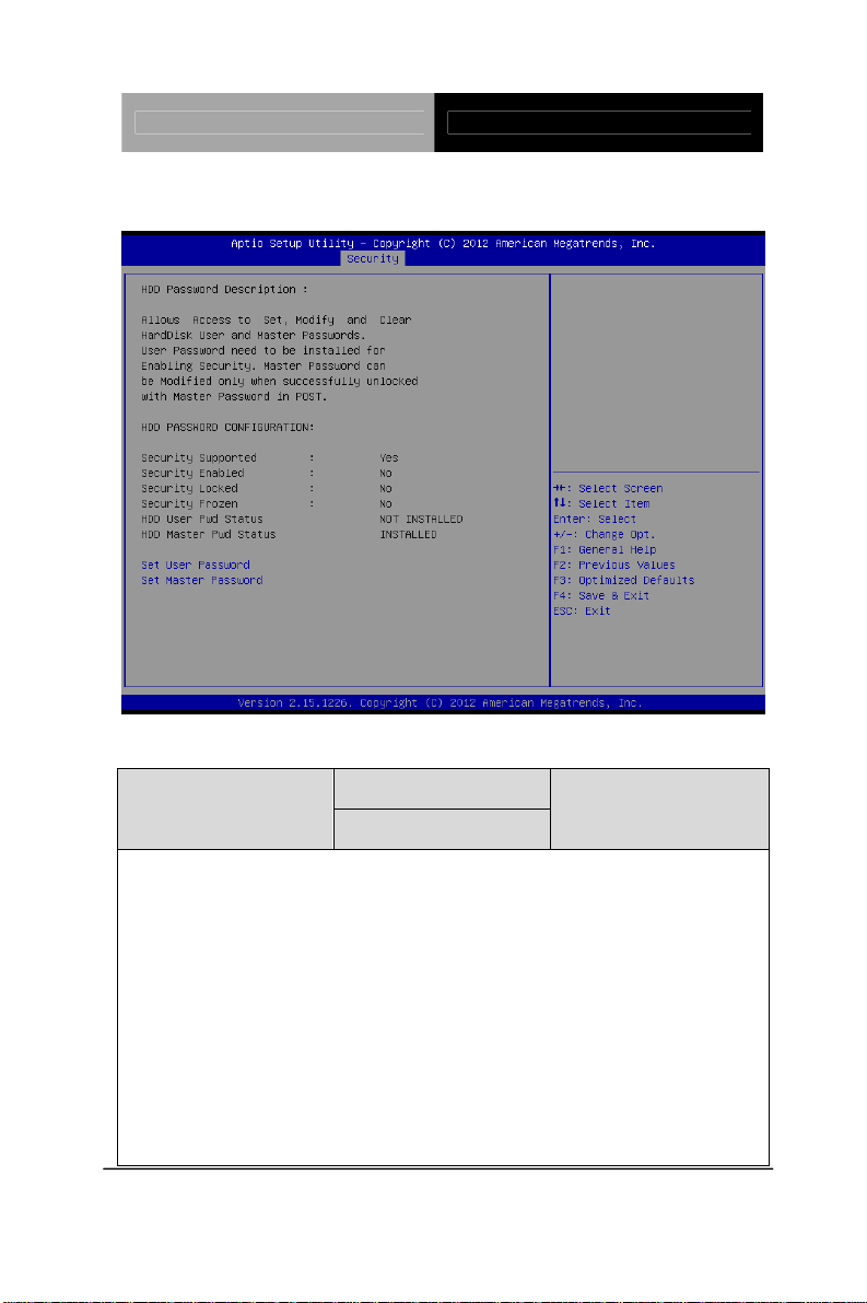
HDD Security
Options summary: (default setting)
Not set
Set Master Password
You can install a Master and User password. Before booting to OS, HDD will be set
to frozen state. On S3 resume HDD will be unlocked using the HDD Password we
entered while system booting.
Install the Password:
Press Enter on this item, a dialog box appears which lets you enter a password. You
can enter no more than six letters or numbers. Press Enter after you have typed in
the password. A second dialog box asks you to retype the password for
confirmation. Press Enter after you have retyped it correctly. The password is
Set User Password/
Chapter 3 AMI BIOS Setup 3-23
Page 46

Touch Panel PC AHP-1083
required at boot time, or when the user enters the Setup utility.
Removing the Password:
Highlight this item and type in the current password. At the next dialog box press
Enter to disable password protection.
Chapter 3 AMI BIOS Setup 3-24
Page 47
Touch Panel PC AHP-1083
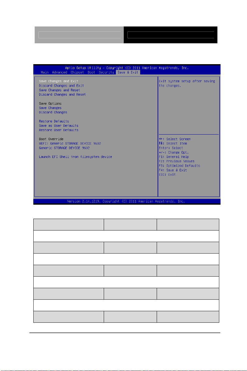
Setup submenu: Exit
Options summary: (default setting)
Save Changes and Reset
Reset the system after saving the changes
Discard Changes and Reset
Reset system setup without saving any changes
Restore Defaults
Restore/Load Default values for all the setup options.
Save as User Defaults
Save the changes done so far as User Defaults
Restore User Defaults
Chapter 3 AMI BIOS Setup 3-25
Page 48

Touch Panel PC AHP-1083
Restore the User Defaults to all the setup options
Chapter 3 AMI BIOS Setup 3-26
Page 49

Touch Panel PC AHP-1083
Chapter
4
Driver
Inst
allation
Chapter 4 Driver Installation 4 - 1
Page 50

Touch Panel PC AHP-1083
The AHP-1083 comes with a CD-ROM that contains all
drivers and utilities that meet your needs.
Follow the sequence below to install the drivers:
Step 1 – Install Chipset Driver
Step 2 – Install VGA Driver
Step 3 – Install LAN Driver
Step 4 – Install AHCI Driver
Step 5 – Install Touch Driver
Step 6 – Install Serial Port Driver (Optional)
Please read instructions below for further detailed
installations.
Chapter 4 Driver Installation 4 - 2
Page 51

Touch Panel PC AHP-1083
4.1 Installation:
Insert the AHP-1083 CD-ROM into the CD-ROM Drive. And install
the drivers from Step 1 to Step 6 in order.
Step 1 – Install Chipset Driver
1. Click on the STEP1-CHIPSET folder and select the OS
folder your system is
2. Double click on the Setup.exe file located in each OS
folder
3. Follow the instructions that the window shows
4. The system will help you install the driver automatically
Step 2 – Install VGA Driver
For Windows
®
7
1. Click on the STEP2-VGA folder and select the folder of
WIN7_32
2. Double click on the Setup.exe file
3. Follow the instructions that the window shows
4. The system will help you install the driver automatically
For Windows
®
XP
1. Install Framework 3.5
Double click on the dotnetfx35.exe
Follow the instructions that the window shows
The system will help you install the driver
automatically
Chapter 4 Driver Installation 4 - 3
Page 52

Touch Panel PC AHP-1083
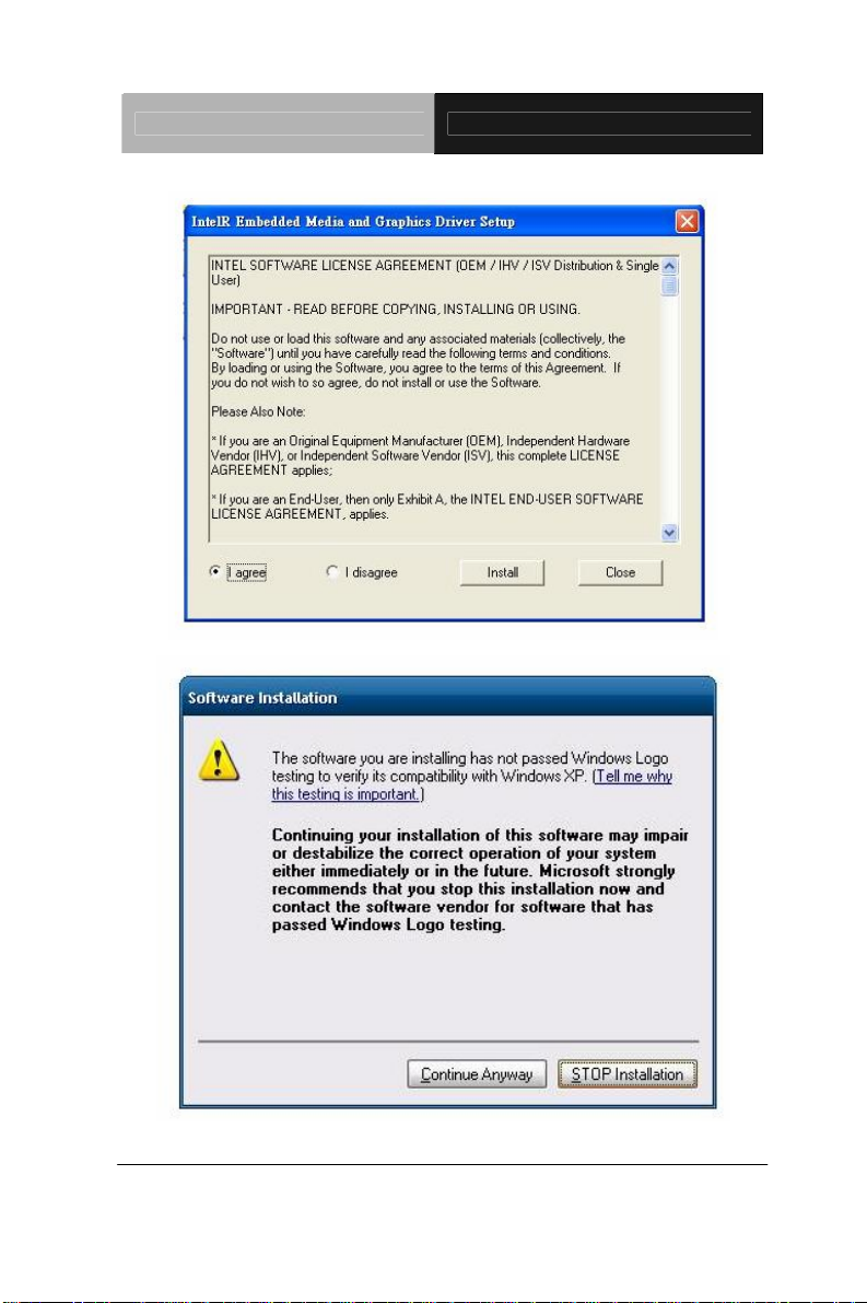
2. Install IEMGD
Double click on the IEMGDInstallCC.exe
Select the configuration
Follow the instructions that the window shows
The system will help you install the driver
automatically
Due to AHP-1083 resolution is 800 x 600, please select
GCV5-n2_800x600x18bit.
Chapter 4 Driver Installation 4 - 4
Page 53
Touch Panel PC AHP-1083
Chapter 4 Driver Installation 4 - 5
Page 54

Touch Panel PC AHP-1083
If you want to update driver, please u nin stall driver first.
Uninstall IE
MGD
1. Double click on the IEMGDInstallCC.exe
2. Follow the instructions that the window shows
3. The system will help you uninstall the driver automatically
Step 3 – Install LAN Driver
1. Click on the Step 3 - LAN folder and select the OS folder
your system is
2. Double click on the Setup.exe file located in each OS
folder
3. Follow the instructions that the window shows
4. The system will help you install the driver automatically
Step 4 – Install AHCI Driver
1. Click on the STEP4-AHCI folder and select the OS folder
your system is
2. Double click on the Setup.exe file located in each OS
Chapter 4 Driver Installation 4 - 6
Page 55

Touch Panel PC AHP-1083
folder
3. Follow the instructions that the window shows
4. The system will help you install the driver automatically
Step 5 – Install Touch Driver
1. Click on the Step 5 - Touch folder and select the OS
folder your system is
2. Double click on the Setup.exe file located in each OS
folder
3. Follow the instructions that the window shows
4. The system will help you install the driver automatically
Step 6 – Install Serial Port Driver (Optional)
1. Click on the STEP6-Serial Port Driver (Optional) folder
and select the OS folder your system is
2. Double click on the Serial Patch v1.0.1_Eng.exe file
located in each OS folder
3. Follow the instructions that the window shows
4. The system will help you install the driver automatically
Note
: If the OS is Chinese version, you may click on Serial
Patch v1.0.1. exe file located in each OS folder.
Chapter 4 Driver Installation 4 - 7
 Loading...