

Page 1

Rugged Expandable
Touch Panel PC
AGP-3175
AGP-3175
Intel® Core™ i7/i5 Processor
Rugged Touch Panel Computer
With 17” TFT LCD &
Two PCI/PCIe expansion slots
AGP-3175 Manual 4th Ed
June 2012
Page 2

Rugged Expandable
Touch Panel PC
AGP-3175
Copyright Notice
This document is copyrighted, 2012. All rights are reserved. The
original manufacturer reserves the right to make improvements to
the products described in this manual at any time without notice.
No part of this manual may be reproduced, copied, translated, or
transmitted in any form or by any means without the prior written
permission of the original manufacturer. Information provided in this
manual is intended to be accurate and reliable. However, the
original manufacturer assumes no responsibility for its use, nor for
any infringements upon the rights of third parties, which may result
from its use.
The material in this document is for product information only and is
subject to change without notice. While reasonable efforts have
been made in the preparation of this document to assure its
accuracy, AAEON, assumes no liabilities resulting from errors or
omissions in this document, or from the use of the information
contained herein.
AAEON reserves the right to make changes in the product design
without notice to its users.
i
Page 3

Rugged Expandable
Touch Panel PC
AGP-3175
Acknowledgments
AMI is a trademark of American Megatrends Inc.
IBM, PC/AT, PS/2 and VGA are trademarks of International
Business Machines Corporation.
Intel
Microsoft Windows
RTL is a trademark of Realtek Semi-Conductor Co., Ltd.
ESS is a trademark of ESS Technology, Inc.
UMC is a trademark of United Microelectronics Corporation.
SMI is a trademark of Silicon Motion, Inc.
Creative is a trademark of Creative Technology LTD.
All other product names or trademarks are properties of their
respective owners.
®
and Core™ i7/i5 are trademarks of Intel® Corporation.
®
is a registered trademark of Microsoft
Corporation.
ii
Page 4

Rugged Expandable
Touch Panel PC
AGP-3175
Packing List
Before you begin installing your card, please make sure that the
following materials have been shipped:
1 AGP-3175
1 Jumper Cap
2 Easy stand & 4 screws
12 Panel Mount clips & screws
1 HDD plate & 4 anti-vibration rubbers & 4 screws
1 Power Cord (optional)
1 CD-ROM for manual (in PDF format) and drivers
If any of these items are missing or damaged, you should cont act y our
distributor or sales representative immediately.
iii
Page 5

Rugged Expandable
Touch Panel PC
AGP-3175
Safety & Warranty
1. Read these safety instructions carefully.
2. Keep this user's manual for later reference.
3. Disconnect this equipment from any AC outlet before cleaning. Do
not use liquid or spray detergents for cleaning. Use a damp cloth.
4. For pluggable equipment, the power outlet must be installed near
the equipment and must be easily accessible.
5. Keep this equipment away from humidity.
6. Put this equipment on a reliable surface during installation.
Dropping it or letting it fall could cause damage.
7. The openings on the enclosure are for air convection. Protect the
equipment from overheating. DO NOT COVER THE OPENINGS.
8. Make sure the voltage of the power source is correct before
connecting the equipment to the power outlet.
9. Position the power cord so that people cannot step on it. Do not
place anything over the power cord.
10. All cautions and warnings on the equipment should be noted.
11. If the equipment is not used for a long time, disconnect it from the
power source to avoid damage by transient over-voltage.
12. Never pour any liquid into an opening. This could cause fire or
electrical shock.
13. Never open the equipment. For safety reasons, only qualified
service personnel should open the equipment.
14. If any of the following situations arises, get the equipment
checked by service personnel:
a. The power cord or plug is damaged.
b. Liquid has penetrated into the equipment.
c. The equipment has been exposed to moisture.
iv
Page 6

Rugged Expandable
Touch Panel PC
AGP-3175
d. The equipment does not work well, or you cannot get it to
work according to the users manual.
e. The equipment has been dropped and damaged.
f. The equipment has obvious signs of breakage.
15. DO NOT LEAVE THIS EQUIPMENT IN AN UNCONTROLLED
ENVIRONMENT WHERE THE STORAGE TEMPERATURE IS
BELOW -20° C (-4°F) OR ABOVE 60° C (140° F). IT MAY
DAMAGE THE EQUIPMENT.
16. External equipment intended for connection to signal input/output
or other connectors, shall comply with relevant UL / IEC standard
(e.g. UL 60950 for IT equipment and UL 2601-1 / IEC 60601
series for medical electrical equipment). In addition, all such
combinations – systems – shall comply with the standard IEC
60601-1-1, Safety requirements for medical electrical systems.
Equipment not complying with UL 2601-1 shall be kept outside
the patient environment, as defined in the standard.
FCC
This device complies with Part 15 FCC
Rules. Operation is subject to the following
two conditions: (1) this device may not
cause harmful interference, and (2) this
device must accept any interference
received including interference that may
cause undesired operation.
v
Page 7
Rugged Expandable
Touch Panel PC
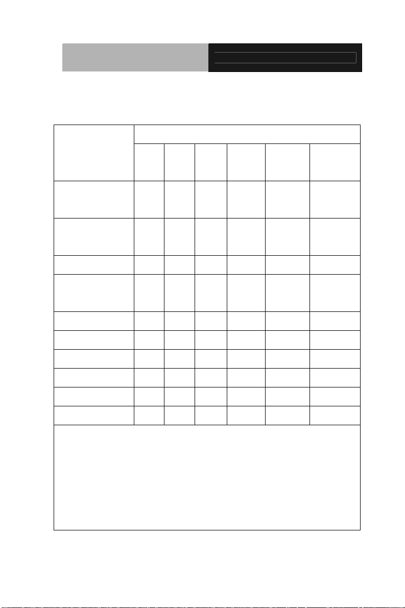
Below Table for China RoHS Requirements
AGP-3175
产品中有毒有害物质或元素名称及含量
AAEON Panel PC/ Workstation
有毒有害物质或元素
部件名称
印刷电路板
及其电子组件
外部信号
连接器及线材
外壳 × ○ ○ ○ ○ ○
中央处理器
与内存
硬盘 × ○ ○ ○ ○ ○
液晶模块 × ○ ○ ○ ○ ○
光驱 × ○ ○ ○ ○ ○
触控模块 × ○ ○ ○ ○ ○
电源 × ○ ○ ○ ○ ○
O:表示该有毒有害物质在该部件所有均质材料中的含量均在
SJ/T 11363-2006 标准规定的限量要求以下。
X:表示该有毒有害物质至少在该部件的某一均质材料中的含量超出
SJ/T 11363-2006 标准规定的限量要求。
备注:
一、此产品所标示之环保使用期限,系指在一般正常使用状况下。
二、上述部件物质中央处理器、内存、硬盘、光驱、触控模块为选购品。
铅
(Pb)汞 (Hg)镉 (Cd)
× ○ ○ ○ ○ ○
× ○ ○ ○ ○ ○
× ○ ○ ○ ○ ○
六价铬
(Cr(VI))
多溴联苯
(PBB)
多溴二苯醚
(PBDE)
vi
Page 8

Rugged Expandable
Touch Panel PC
Contents
Chapter 1 General Information
1.1 Introduction................................................................ 1-2
1.2 Feature......................................................................1-3
1.3 Specification.............................................................. 1-4
1.4 Dimension ................................................................. 1-7
Chapter 2 Hardware Installation
2.1 Safety Precautions.................................................... 2-2
2.2 Location of Connectors and Jumpers of the Main
Board............................................................................... 2-3
2.3 List of Jumpers.......................................................... 2-5
2.4 List of Connectors .....................................................2-5
AGP-3175
2.5 Setting Jumpers ........................................................2-6
2.6 CMOS Setting (CMOS1)...........................................2-7
2.7 Auto PWRBTN Selection (JP1).................................2-7
2.8 CFD Voltage 3.3V/5V Selection (JP2) ......................2-7
2.9 TPM Setting (JP3)..................................................... 2-7
2.10 COM1 +12V/+5V/RING Selection (JP5) .................2-7
2.11 COM2 +12V/+5V/RING Selection (JP6) .................2-8
2.12 COM1~2 Port LED Connector (CN8)......................2-8
2.13 COM3~4 Port LED Connector (CN9)......................2-8
2.14 LAN Port LED Connector (CN10) ...........................2-8
2.15 RS-232/422/485 Pin Header (COM2).....................2-9
vii
Page 9

Rugged Expandable
Touch Panel PC
2.16 RS-232 Pin Header (COM3~4)...............................2-9
2.17 SATA Connector (SATA 1~3) .................................2-9
2.18 SATA Power Connector (PWR1)............................ 2-9
2.19 Hard Disk Drive Installation..................................... 2-10
2.20 Easy Stand Installation............................................ 2-14
2.21 Panel Mount Kit Installation..................................... 2-17
2.22 Waterproof Protection .............................................2-18
Chapter 3 AMI BIOS Setup
3.1 System Test and Initialization. ..................................3-2
3.2 AMI BIOS Setup........................................................ 3-3
Chapter 4 Driver Installation
4.1 Installation................................................................. 4-3
AGP-3175
viii
Page 10

Rugged Expandable
Touch Panel PC
AGP-3175
Chapter
1
General
Information
Chapter 1 General Information 1-1
Page 11

Rugged Expandable
Touch Panel PC
AGP-3175
1.1 Introduction
AGP-3175 is first product of the Rugged Expandable Touch Panel
Solution series. It adopts Intel
®
Core™ i7/i5 processor with two
DDR3 800/1066 MHz SODIMM up to 8 GB.
Best performance for multimedia solution
AAEON's AGP-3175 also supports Intel
®
Core™ i7/i5 + QM57
chipset and the LVD/CRT Controller has been integrated in QM57.
In addition, it equips versatile I/O ports, such as two RS-232, one
RS-232/422/485, six USB2.0, one Line-out/MIC-in/Line-in, one
Keyboard/Mouse, and one VGA. Therefore, AGP-3175 can be
broadly implemented in several markets, such as Factory Control
Center, Railway Control Center, and Transportation markets.
Multi-Function Intel
®
Core™ i7/i5 Platform
AGP-3175 integrates 17” color TFT LCD. Moreover, the modular
design for CPU board is easy for you to replace. With flexible
expansion, you get easy access to solutions ranging from Modem,
Storage, Sound Card, SCSI card, Audio/Video capture card,
Wireless LAN module, to Bluetooth module. Furthermore, you may
choose one Mini Card, two PCI or two PCI-Express slots for
necessary expansions. If you are looking for powerful and robust
Touch Panel Computer, AGP-3175 is an ideal solution for your
applications.
Chapter 1 General Information 1-2
Page 12

Rugged Expandable
Touch Panel PC
AGP-3175
1.2 Feature
z 17” SXGA (1280 x 1024) TFT LCD Display
z Intel
z Easy-To-Expand: Two PCI/PCIe Slots
z IP-65 Aluminum Die Cast Front Bezel
z Two Easy Access Front USB Ports
z Modular Design For CPU Board
®
Core™ i7/i5 Processor
Chapter 1 General Information 1-3
Page 13

Rugged Expandable
Touch Panel PC
1.3 Specification
AGP-3175
System
®
Core™ i7/i5 Processor
z Processor
z Memory DDR3 800/1066 MHz SODIMM x 2, up
Intel
to 8 GB
z Chipset Intel
z LCD / CRT Integrated in QM57
z Ethernet 10/100/1000Base-TX, RJ-45 x 2
z I/O Port RS-232 x 2, RS-232/422/485 x 1,
®
Core™ i7/i5 + QM57
USB2.0 x 6 (2 on front, 4 on rear),
Line-out/MIC-in/Line-in x 1, PS/2 x 1 for
Keyboard/Mouse, DVI x 1
z Storage Disk Drive 3.5” SATA Hard Disk Drive x 2, Slim
DVD-Combo (optional)
z Expansion Slot Mini Card x 1, PCI slot x 2 or PCIe x 2
z OS Support Windows
®
XP, Windows® 7, Linux
Fedora
Mechanical
z Construction IP-65/ NEMA4 for Aluminum die cast
front bezel & Aluminum chassis
Chapter 1 General Information 1-4
Page 14

Rugged Expandable
Touch Panel PC
AGP-3175
z Mounting Panel/ Desktop/ Rack
z Dimension 16.53” x 13.95” x 4.65” (420mm x
355mm x 118mm)
z Carton Dimension 24.21”(L) x 20.47”(W) x 12.99” (H)
(615mm x 520mm x 330mm)
z Gross Weight 24.2 lb (11 kg)
z Net Weight 20.9 lb (9.5 kg)
Environmental
z Operating
32oF ~122oF (0oC~50oC) (Ambient with
Temperature
z Storage Tenoeratyre -4
z Storage Humidity 10%~95% @ 40
z Vibration 1 g rms/ 5~500 Hz/ Random operation
airflow)
o
F ~140oF (-20oC~60oC)
o
C, non-condensing
(HDD)
z Shock 20 G peak acceleration (11 msec.
duration)
z EMC CE/FCC Class A
Power Supply
z AC input 250W 110/230V AC power
Chapter 1 General Information 1-5
Page 15

Rugged Expandable
Touch Panel PC
AGP-3175
LCD
z Display Type 17” Color TFT LCD
z Max. Resolution 1280 x 1024
z Max. Colors 16.7 M colors (6/8-bit for R,G,B)
z Luminance 380 cd/m
z Viewing Angle
170°(H)
2
160°(V)
z Back Light MTBF
50,000
(Hrs)
Touch Screen
z Type 5-wire resistive
z Light transmission 80%
z Lifetime 35 million activations
Chapter 1 General Information 1-6
Page 16

Rugged Expandable
Touch Panel PC
1.4 Dimension
AGP-3175
Cut size: 407 x 341 cm
Chapter 1 General Information 1-7
Page 17

Rugged Expandable
Touch Panel PC
AGP-3175
Chapter
2
Hardware
Inst
Chapter 2 Hardware Installation 2-1
allation
Page 18

Rugged Expandable
Touch Panel PC
2.1 Safety Precautions
Always completely disconnect the power cord
from your board whenever you are working on
it. Do not make connections while the power is
on, because a sudden rush of power can
damage sensitive electronic components.
Always ground yourself to remove any static
charge before touching the board. Modern
electronic devices are very sensitive to static
electric charges. Use a grounding wrist strap at
all times. Place all electronic components on a
static-dissipative surface or in a static-shielded
AGP-3175
bag when they are not in the chassis
Chapter 2 Hardware Installation 2-2
Page 19

Rugged Expandable
Touch Panel PC
AGP-3175
2.2 Location of Connectors and Jumpers of the Main Board
Component Side
Chapter 2 Hardware Installation 2-3
Page 20

Rugged Expandable
Touch Panel PC
Solder Side
AGP-3175
Chapter 2 Hardware Installation 2-4
Page 21

Rugged Expandable
Touch Panel PC
AGP-3175
2.3 List of Jumpers
There are a number of jumpers in the board that allow you to
configure your system to suit your application.
The table below shows the function of each jumper in the board:
Label Function
CMOS1 CMOS Setting Selection
JP1 Auto PWRBTN Selection
JP2 CFD Voltage 3.3V/5V Selection
JP3 TPM Setting Selection
JP5 COM1 +12V/+5V/RING Selection
JP6 COM2 +12V/+5V/RING Selection
2.4 List of Connectors
There are a number of connectors in the board that allow you to
configure your system to suit your application. The table below
shows the function of each connector in the board:
Label Function
CN8 COM1~2 Port LED
CN9 COM3~4 Port LED
CN10 LAN Port LED
COM2 RS-232/422/485 Pin header
COM3~4 RS-232 Pin header
SATA1~SATA3 SATA Connector
PWR1 SATA Power Connector
Chapter 2 Hardware Installation 2-5
Page 22

Rugged Expandable
Touch Panel PC
AGP-3175
2.5 Setting Jumpers
You configure your card to match the needs of your application by
setting jumpers. A jumper is the simplest kind of electric switch. It
consists of two metal pins and a small metal clip (often protected by
a plastic cover) that slides over the pins to connect them. To “close”
a jumper you connect the pins with the clip.
To “open” a jumper you remove the clip. Sometimes a jumper will
have three pins, labeled 1, 2 and 3. In this case you would connect
either pins 1 and 2 or 2 and 3.
3
2
1
Open Closed Closed 2 -3
A pair of needle-nose pliers may be helpful when working with
jumpers.
If you have any doubts about the best hardware configuration for
your application, contact your local distributor or sales
representative before you make any change.
Generally, you simply need a standard cable to make most
connections.
Chapter 2 Hardware Installation 2-6
Page 23

Rugged Expandable
Touch Panel PC
2.6 CMOS Setting (CMOS1)
JP1 Function
1-2 Normal (Default)
2-3 Clear CMOS
2.7 Auto PWRBTN Selection (JP1)
JP1 Function
1-2 Don’t use Auto PWRBTN (Default)
2-3 Use Auto PWRBTN
2.8 CFD Voltage 3.3V/5V Selection (JP2)
JP2 Function
1-2 +3.3V
2-3 +5V (Default)
2.9 TPM Setting (JP3)
JP3 Function
1-2 Save ME RTC Register (Default)
AGP-3175
2-3 Clear ME RTC Register
2.10 COM1 +12V/+5V/RING Selection (JP5)
JP5 Function
1-2 +12V
3-4 Ring (Default)
5-6 +5V
Chapter 2 Hardware Installation 2-7
Page 24

Rugged Expandable
Touch Panel PC
AGP-3175
2.11 COM2 +12V/+5V/RING Selection (JP6)
JP6 Function
1-2 +12V
3-4 Ring (Default)
5-6 +5V
2.12 COM1~2 Port LED Connector (CN8)
Pin Signal Pin Signal
1 COM1_RS232_PWR 2 GND
3 TX_LED_COM1 4 GND
5 RX_LED_COM1 6 GND
7 COM2_RS232_PWR 8 GND
9 TX_LED_COM2 10 GND
11 RX_LED_COM2 12 GND
13 COM2_RS485_PWR 14 COM2_RS422_PWR
2.13 COM3~4 Port LED Connector (CN9)
Pin Signal Pin Signal
1 COM3_RS232_PWR 2 GND
3 TX_LED_COM3 4 GND
5 RX_LED_COM3 6 GND
7 COM4_RS232_PWR 8 GND
9 TX_LED_COM4 10 GND
11 RX_LED_COM4 12 GND
2.14 LAN Port LED Connector (CN10)
Pin Signal Pin Signal
1 LAN1_LED_D2 2 LAN1_LED_LNK#_ACT
3 LAN1_LED_1000# 4 LAN1_LED_100#
Chapter 2 Hardware Installation 2-8
Page 25

Rugged Expandable
Touch Panel PC
AGP-3175
5 LAN2_LED_D2 6 ACT_2_LED
7 SPD1K_2_LED 8 SPD100_2_LED
2.15 RS-232/422/485 Pin Header (COM2)
Pin Signal Pin Signal
1 DCD 2 RXD
3 TXD 4 DTR
5 GND 6 DSR
7 RTS 8 CTS
9 RI
2.16 RS-232 Pin Header (COM3~4)
Pin Signal Pin Signal
1 DCD 2 RXD
3 TXD 4 DTR
5 GND 6 DSR
7 RTS 8 CTS
9 RI
2.17 SATA Connector (SATA 1~3)
Pin Signal Pin Signal
1 GND 2 TXP
3 TXN 4 GND
5 RXN 6 RXP
7 GND
2.18 SATA Power Connector (PWR1)
Pin Signal Pin Signal
1 +12V 2 GND
3 GND 4 +5V
Chapter 2 Hardware Installation 2-9
Page 26

Rugged Expandable
Touch Panel PC
AGP-3175
2.19 Hard Disk Drive Installation
In the following, we will guide you how to install Hard Disk Drive
(HDD). Make sure that all parts are provided before you start the
installation.
Step 1
: Loosen the five screws on the back chassis of AGP-3175
Step 2
: Open the back cover of the AGP-3175
Chapter 2 Hardware Installation 2-10
Page 27

Rugged Expandable
Touch Panel PC
AGP-3175
Step 3: Get the accessories of anti-vibration rubbers and screws
ready
: Get the screws from the rubbers and insert the
Step 4
anti-vibration rubbers into the fillister of the HDD bracket first
: Insert the screws to the anti-vibration rubbers
Step 5
Chapter 2 Hardware Installation 2-11
Page 28

Rugged Expandable
Touch Panel PC
Step 6
: Put the HDD to the HDD bracket
AGP-3175
Chapter 2 Hardware Installation 2-12
Page 29

Rugged Expandable
Touch Panel PC
AGP-3175
Step 7: Connect the SATA and Power Cables to the HDD
Step 8: Fasten the HDD bracket to the chassis
Chapter 2 Hardware Installation 2-13
Page 30

Rugged Expandable
Touch Panel PC
AGP-3175
2.20 Easy Stand Installation
There’re two L-shaped easy stands come with the product. Refer to
the following illustration to install it.
1. Fix the L-shaped easy stands with the screws on both
sides of the AGP-3175. See the illustration below:
Chapter 2 Hardware Installation 2-14
Page 31

Rugged Expandable
Touch Panel PC
AGP-3175
2.21 Panel Mount Kit Installation
Some screw sets will come with the product for user to mount the
AGP-3175 on the wall. See the steps below along with the
illustration.
Step 1
: Bore the screw into the screw nut.
Step 2
: Locate the screw set into the hole around the monitor as
the right illustration and pull it back to lock the screw set
on the hole.
: Turn the screw around to make it tight until it is closed to
Step 3
the wall.
: Lock the monitor to the wall with the screw set and finish
Step 4
the installation
Chapter 2 Hardware Installation 2-15
Page 32

Rugged Expandable
Touch Panel PC
AGP-3175
2.22 Waterproof Protection
Step 1: Remove the non-sticky aspect of the double sided tape from the
waterproof rubber border.
: Put the waterproof rubber border along the bracket of the
Step 2
AGP-3125 chassis.
Chapter 2 Hardware Installation 2-16
Page 33

Rugged Expandable
Touch Panel PC
AGP-3175
Chapter 2 Hardware Installation 2-17
Page 34

Rugged Expandable
Touch Panel PC
AGP-3175
Chapter
3
AMI
BIOS Setup
Chapter 3 AMI BIOS Setup 3-1
Page 35

Rugged Expandable
Touch Panel PC
AGP-3175
3.1 System Test and Initialization
These routines test and initialize board hardware. If the routines
encounter an error during the tests, you will either hear a few short
beeps or see an error message on the screen. There are two kinds
of errors: fatal and non-fatal. The system can usually continue the
boot up sequence with non-fatal errors.
System configuration verification
These routines check the current system configuration against the
values stored in the CMOS memory. If they do not match, the
program outputs an error message. You will then need to run the
BIOS setup program to set the configuration information in memory.
There are three situations in which you will need to change the
CMOS settings:
1. You are starting your system for the first time
2. You have changed the hardware attached to your system
3. The CMOS memory has lost power and the configuration
information has been erased.
The AGP-3175 CMOS memory has an integral lithium battery
backup for data retention. However, you will need to replace the
complete unit when it finally runs down.
Chapter 3 AMI BIOS Setup 3-2
Page 36

Rugged Expandable
Touch Panel PC
AGP-3175
3.2 AMI BIOS Setup
AMI BIOS ROM has a built-in Setup program that allows users to
modify the basic system configuration. This type of information is
stored in battery-backed CMOS RAM so that it retains the Setup
information when the power is turned off.
Entering Setup
Power on the computer and press <Del> or <F2> immediately. This
will allow you to enter Setup.
Main
Set the date, use tab to switch between date elements.
Advanced
Enable disable boot option for legacy network devices.
Chipset
Host bridge parameters.
Boot
Enables/disable quiet boot option.
Security
Set setup administrator password.
Save&Exit
Exit system setup after saving the changes.
Chapter 3 AMI BIOS Setup 3-3
Page 37

Rugged Expandable
Touch Panel PC
AGP-3175
Chapter
4
Driver
Inst
allation
Chapter 4 Driver Installation 4-1
Page 38

Rugged Expandable
Touch Panel PC
AGP-3175
The AGP-3175 comes with a DVD-ROM that contains all drivers
your need.
Follow the sequence below to install the drivers:
Step 1 – Install Chipset Driver
Step 2 – Install VGA Driver
Step 3 – Install LAN Driver
Step 4 – Install AUDIO Driver
Step 5 – Install ME Driver
Step 6 – Install Touch Panel Driver
Please read following instructions for detailed installations.
Chapter 4 Driver Installation 4-2
Page 39

Rugged Expandable
Touch Panel PC
AGP-3175
4.1 Installation:
Insert the AGP-3175 DVD-ROM into the DVD-ROM Drive. And
install the drivers from Step 1 to Step 6 in order.
Step 1 – Install Chipset Driver
1. Click on the STEP1-CHIPSET folder and select the OS
your system is
2. Double click on the Setup.exe file located in each OS
folder
3. Follow the instructions that the window shows
4. The system will help you to install the driver automatically
Step 2 – Install VGA Driver
1. Click on the STEP2-VGA folder and select the OS your
system is
2. Double click on Setup.exe file located in each OS folder
3. Follow the instructions that the window shows
4. The system will help you to install the driver automatically
Step 3 – Install LAN Driver
1. Click on the STEP3-LAN folder and select the OS your
system is
2. Double click on Autorun.exe file located in each OS
folder
3. Follow the instructions that the window shows
4. The system will help you to install the driver automatically
Chapter4 Drivers Installation 4-3
Page 40

Rugged Expandable
Touch Panel PC
AGP-3175
Step 4 – Install AUDIO Driver
1. Click on the STEP4-AUDIO folder and select the OS your
system is
2. Double click on .exe file located in each OS folder
3. Follow the instructions that the window shows
4. The system will help you to install the driver automatically
Step 5 – Install ME Driver
1. Click on the STEP5-ME folder and select the OS your
system is
2. Double click on Setup.exe file located in each OS folder
3. Follow the instructions that the window shows
4. The system will help you to install the driver automatically
Step 6 – Install Touch Panel Driver
1. Click on the STEP6-Touch Panel Driver folder and
select the OS your system is
2. Double click on setup.exe file located in each OS folder
3. Follow the instructions that the window shows
4. The system will help you to install the driver automatically
Chapter 4 Driver Installation 4-4
 Loading...