

Page 1
Remote Touch Display AGD-317R
AGD-317R
17” SXGA (1280x1024)
Rugged Touch Display
With Remote Display Technology
IP-65 Front Bezel
Multi-Touch Window Design (Two-Point)
AGD-317R Manual 1
st
Ed
April 2012
Page 2

Remote Touch Display AGD-317R
Copyright Notice
This document is copyrighted, 2012. All rights are reserved. The
original manufacturer reserves the right to make improvements to
the products described in this manual at any time without notice.
No part of this manual may be reproduced, copied, translated, or
transmitted in any form or by any means without the prior written
permission of the original manufacturer. Information provided in this
manual is intended to be accurate and reliable. However, the
original manufacturer assumes no responsibility for its use, nor for
any infringements upon the rights of third parties, which may result
from its use.
The material in this document is for product information only and is
subject to change without notice. While reasonable efforts have
been made in the preparation of this document to assure its
accuracy, AAEON, assumes no liabilities resulting from errors or
omissions in this document, or from the use of the information
contained herein.
AAEON reserves the right to make changes in the product design
without notice to its users.
i
Page 3

Remote Touch Display AGD-317R
Acknowledgments
Intel
IBM, PC/AT, PS/2 are trademarks of International Busine ss
®
is registered trademarks of Intel® Corporation.
Machines Corporation.
Microsoft
®
Windows is a registered trademark of Microsoft®
Corporation.
RTL is a trademark of Realtek Semi-Conductor Co., Ltd.
C&T is a trademark of Chips and Technologies, Inc.
UMC is a trademark of United Microelectronics Corporation.
ITE is a trademark of Integrated Technology Express, Inc.
SiS is a trademark of Silicon Integrated Systems Corp.
VIA is a trademark of VIA Technology, Inc.
All other product names or trademarks are properties of their
respective owners.
ii
Page 4

Remote Touch Display AGD-317R
Packing List
The LCD monitor comes with the following standard parts shown as
below. Check and make sure they are included and in good condition.
If anything is missing or damaged, contact the dealer immediately.
1 AGD-317R
1 Utility CD-ROM
Contains User’s Manual (in PDF format), Drivers and
Utilities
1 AC/DC 12V Power Adapter with Lock
If any of these items are missing or damaged, you should cont act y our
distributor or sales representative immediately.
iii
Page 5

Remote Touch Display AGD-317R
Safety & Warranty
1. Read these safety instructions carefully.
2. Keep this user's manual for later reference.
3. Disconnect this equipment from any AC outlet before cleaning. Do
not use liquid or spray detergents for cleaning. Use a damp cl oth.
4. For pluggable equipment, the power outlet must be installed near
the equipment and must be easily accessible.
5. Keep this equipment away from humidity.
6. Put this equipment on a reliable surface during installation.
Dropping it or letting it fall could cause damage.
7. The openings on the enclosure are for air convection. Protect the
equipment from overheating. DO NOT COVER THE OPENINGS.
8. Make sure the voltage of the power source is correct before
connecting the equipment to the power outlet.
9. Position the power cord so that people cannot step on it. Do not
place anything over the power cord.
10. All cautions and warnings on the equipment should be noted.
11. If the equipment is not used for a long time, disconnect it from the
power source to avoid damage by transient over-voltage.
12. Never pour any liquid into an opening. This could cause fire or
electrical shock.
13. Never open the equipment. For safety reasons, only qualified
service personnel should open the equipment.
iv
Page 6
Remote Touch Display AGD-317R
14. If any of the following situations arises, get the equipment
checked by service personnel:
a. The power cord or plug is damaged.
b. Liquid has penetrated into the equipment.
c. The equipment has been exposed to moisture.
d. The equipment does not work well, or you cannot get it to
work according to the users manual.
e. The equipment has been dropped and damaged.
f. The equipment has obvious signs of breakage.
15. DO NOT LEAVE THIS EQUIPMENT IN AN UNCONTROLLED
ENVIRONMENT WHERE THE STORAGE TEMPERATURE IS
BELOW -20° C (-4°F) OR ABOVE 70° C (158° F). IT MAY
DAMAGE THE EQUIPMENT
.
FCC
Cautio
This device complies with Part 15 FCC Rules.
Operation is subject to the following two
conditions: (1) this device may not cause
harmful interference, and (2) this device
must accept any interference received
including interference that may cause
undesired operation.
n:
It may cause the danger of explosion if battery is incorrectly
replaced. Replace only with same or equivalent type
recommended by the manufacturer.
v
Page 7
Remote Touch Display AGD-317R
Below Table for China RoHS Requirements
产品中有毒有害物质或元素名称及含量
AAEON Display
有毒有害物质或元素
部件名称
印刷电路板
及其电子组件
外部信号
连接器及线材
外壳 × ○ ○ ○ ○ ○
液晶模块 × ○ ○ ○ ○ ○
触控模块 × ○ ○ ○ ○ ○
电源 × ○ ○ ○ ○ ○
O:表示该有毒有害物质在该部件所有均质材料中的含量均在
SJ/T 11363-2006 标准规定的限量要求以下。
X:表示该有毒有害物质至少在该部件的某一均质材料中的含量超出
SJ/T 11363-2006 标准规定的限量要求。
备注:
一、此产品所标示之环保使用期限,系指在一般正常使用状况下。
二、上述部件物质触控模块为选购品。
铅
(Pb)汞 (Hg)镉 (Cd)
× ○ ○ ○ ○ ○
× ○ ○ ○ ○ ○
六价铬
(Cr(VI))
多溴联苯
(PBB)
多溴二苯醚
(PBDE)
vi
Page 8

Remote Touch Display AGD-317R
Contents
Chapter 1 General Information
1.1 Introduction................................................................ 1-2
1.2 Features....................................................................1-3
1.3 General Specification................................................1-4
1.4 Dimension .................................................................1-7
1.5 Network Topology ..................................................... 1-8
Chapter 2 Hardware Installation
2.1 Before Unpacking...................................................... 2-2
2.2 Connecting Power and Cables..................................2-3
2.3 Panel Mounting ......................................................... 2-4
2.4 Desktop, Swing-ARM Mounting................................2-5
2.5 VESA Wall Mounting................................................. 2-6
2.6 LED Definitions..........................................................2-8
2.7 Button Definitions......................................................2-8
2.8 DIP Switch.................................................................2-11
2.9 Connecting Power of Remote Display ...................... 2-12
2.10 Connecting I/O Connectors of Remote Display......2-12
2.11 Connection Debugging............................................ 2-13
2.12 The Matching of the Remote Box and Remote
Display............................................................................. 2-14
vii
Page 9

Remote Touch Display AGD-317R
Chapter 3 On Screen Display Control
3.1 On Screen Display (OSD) Board Description. .......... 3-2
3.2 OSD Main Menu: Push The MENU Keys..................3-3
3.3 Select Input Source................................................... 3-4
3.4 Contrast/ Brightness- Submenu................................ 3-5
3.5 Geometry Menu.........................................................3-6
3.6 Color Temperature- Submenu OSD Main Menu: Push
The MENU Keys.............................................................. 3-7
3.7 RGB Color- Submenu. .............................................. 3-8
3.8 Language- Submenu................................................. 3-9
3.9 Auto Config- Submenu..............................................3-10
3.10 Mode Resolution- Submenu Chapter...................... 3-11
3.11 Exit Menu- Submenu............................................... 3-12
Chapter 4 Touch Screen Driver Installation
4.1 Introduction................................................................ 4-2
4.2 Resistive Touch screen Driver Installation................ 4-5
4.3 Installing Driver for Windows
®
XP/ Windows® 7 / Linux4-7
viii
Page 10

Remote Touch Display AGD-317R
Chapter
1
Information
General
Chapter 1 General Information 1-1
Page 11

Remote Touch Display AGD-317R
1.1 Introduction
Thank you for purchasing of the Infotainment Touch Display with
Remote Display Technology - a marvelous contribution of
cutting-edge technology.
The LCD monitor has been designed with serious thoughts to
present the best performance for most applications. Symbol of
elegance, its compact and slim profile are well suited in working
locations where space is at a premium.
The TFT LCD monitor displays sharper, more brilliant, crisper and
flicker-free images. Complying with the power management
regulations of VESA DPMS, the LCD monitor is extremely energy
efficient and a power saver. Plus, the LCD monitor has extremely
low radiation emissions and near zero electromagnetic fields which
are supreme benefits.
Fully compatible with PC system, the LCD monitor provides full
interface for all sorts of related standards. Supported by “Plug &
Play” complying with DDC1/DDC2B, installing the LCD monitor is
absolutely trouble free.
The On Screen Display menu provides user a convenient interface
to make right adjustment for optimum display performance.
Chapter 1 General Information 1-2
Page 12

Remote Touch Display AGD-317R
1.2 Features
17” SXGA (1280x1024) TFT LCD Display
Supports Remote Display Technology
IP65 Aluminum Die Cast Front Bezel
Supports On Screen Display (OSD) Function
Chapter 1 General Information 1-3
Page 13

Remote Touch Display AGD-317R
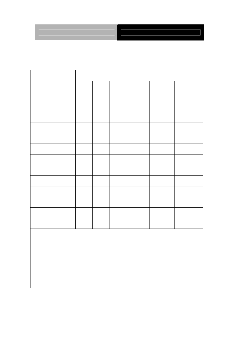
1.3 General Specification
System
Input signal
Control
I/O connector
OS Support
Mechanical
Construction
Mounting
Dimension
Carton
Dimension
Gross Weight
VGA, DVI
Menu, Auto, LCD on/off, Up, Down
AGD-317R-A2: USB x 3 (2 on front, 1 on
rear), LAN x 1, Line-out x 1
AGD-317R-A1: LAN x 2, Line-out x 1
Windows
®
XP, Linux Fedora, Windows® 7
IP65/NEMA4 for aluminum die cast front
bezel and steel chassis
Panel/ VESA 75/100 / Rack
16.54” x 14.1” x 4.41” (420mm x 358mm x
112mm)
26” x 19.53” x 7.87” (661mm x 496mm x
200mm)
18.59 lb (8.45 Kg)
Net Weight
Environmental
Operating
Temperature
Chapter 1 General Information 1-4
14.3 lb (6.5 Kg)
32°F~ 122°F (0°C ~ 50°C)
Page 14

Remote Touch Display AGD-317R
Storage
-4°F~ 158°F (-20°C ~ 70°C)
Temperature
Storage
Humidity
Vibration
Shock
EMC
Power Supply
DC Input
LCD
Display Type
Max.
Resolution
10%~95% @ 40°C, non-condensing
1g rms/5-500Hz/random operation
20 G peak acceleration (11 msec. duration)
CE/FCC Class A
9V~30V DC, w/3-pin terminal block
Over-voltage (31V DC)
Under-voltage (8V DC)
Reverse protection
Surge protection (1000V DC)
17” TFT-LCD
1280 x 1024
Max. Colors
Luminance
Viewing Angle
Backlight
Backlight
16.7M colors (6/8-bit for R, G, B)
380 cd/m
2
170°(H)/ 160°(V)
CCFL
50,000
MTBF (hours)
Chapter 1 General Information 1-5
Page 15

Remote Touch Display AGD-317R
Touchscreen
Type
Light
5-wire resistive (AGD-317R-A2 only)
83%
Transmission
Lifetime (times)
Note: Users have to select the ACG-203 to work with the AGD-317R
35 million activations
Chapter 1 General Information 1-6
Page 16
Remote Touch Display AGD-317R
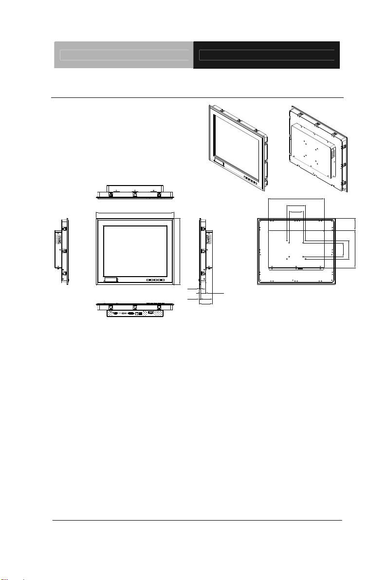
1.4 Dimension
419.79
357.79
6.00
28.00
64.40
7.50
71.90
302.40
100.00
75.00
64.90202.00
75.00
100.00
Chapter 1 General Information 1-7
Page 17
Remote Touch Display AGD-317R
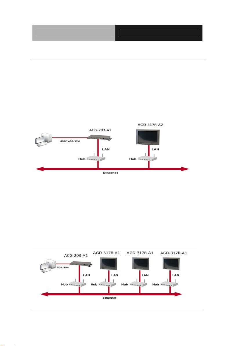
1.5 Network Topology
One-to-one Network
The purpose of a one-to-one network is to allow a display to be used
anywhere away from the host PC. The display can be placed at any
location with Ethernet access. The entire VGA/DVI signal will be
transmitted from a host PC to a remote display via the Ethernet.
One-to-Multiple Network
The one-to-multiple network is a special design for digital signage
applications to show the same screen/audio in different display monitors.
The display can be placed in any area where you can get an Ethernet
connection. The screen & audio which is from the host PC can be shown in
remote displays via Ethernet.
Chapter 1 General Information 1-8
Page 18
Remote Touch Display AGD-317R
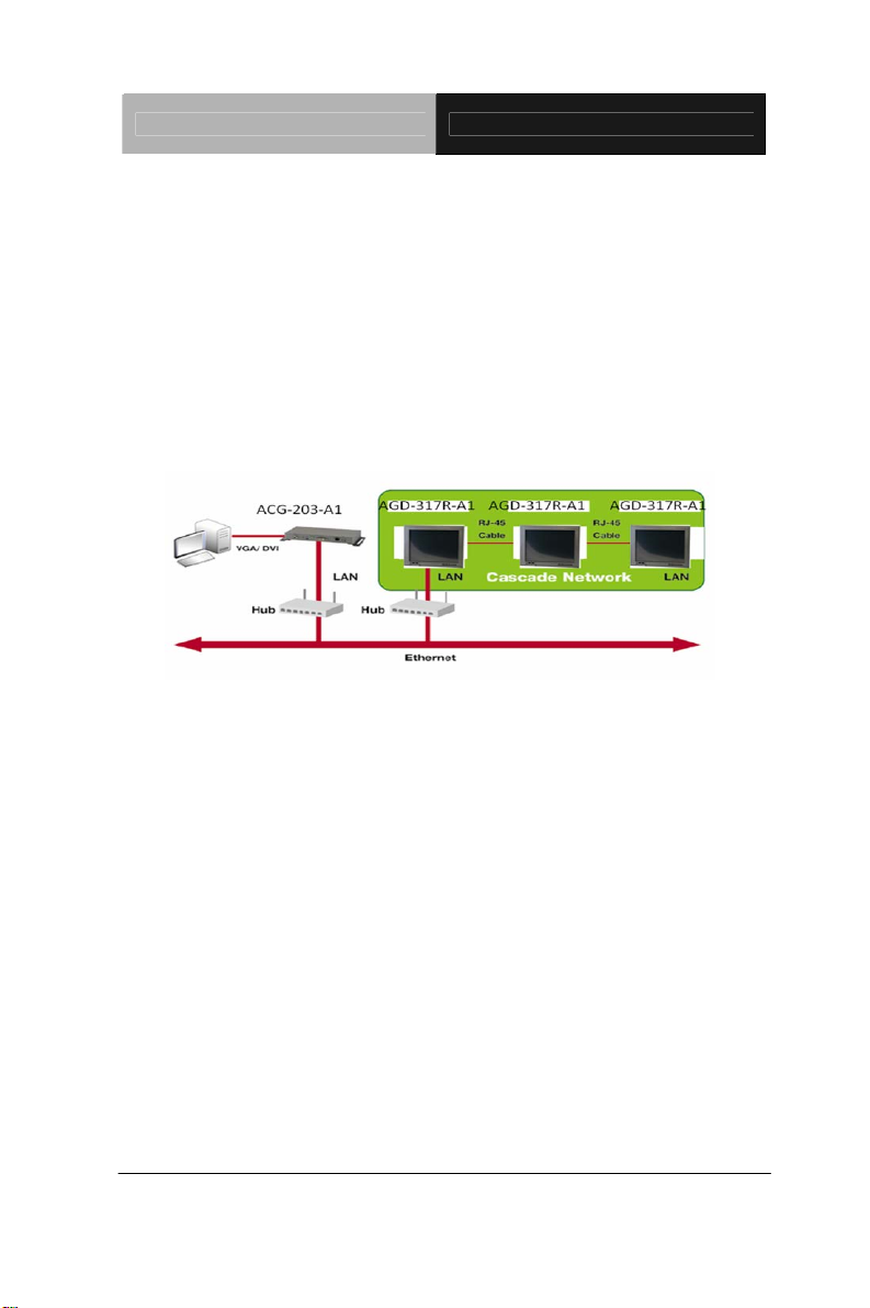
Cascade Network
The purpose of a cascade network is to save on cabling installation costs. It
is specially designed for digital signage applications with limited space
such as trains, buses and airports. With a cascade network set up, an end
user can deploy digital signage displays easily and save on installation
costs.
Chapter 1 General Information 1-9
Page 19

Remote Touch Display AGD-317R
Chapter
2
H
Chapter 2 Hardware Installation 2-1
ardware
Inst
allation
Page 20

Remote Touch Display AGD-317R
2.1 Before Unpacking
It is very important to place the LCD Display in a suitable
environment.
The surface for placing the LCD Display should be
stable and level.
Make sure the place has good ventilation, and out of
direct sunlight; away form sources of excessive dust,
dirt, heat, water, moisture and vibration.
Convenience for connecting the LCD Display the
related facilities should be well considered too.
Chapter 2 Hardware Installation 2-2
Page 21
Remote Touch Display AGD-317R
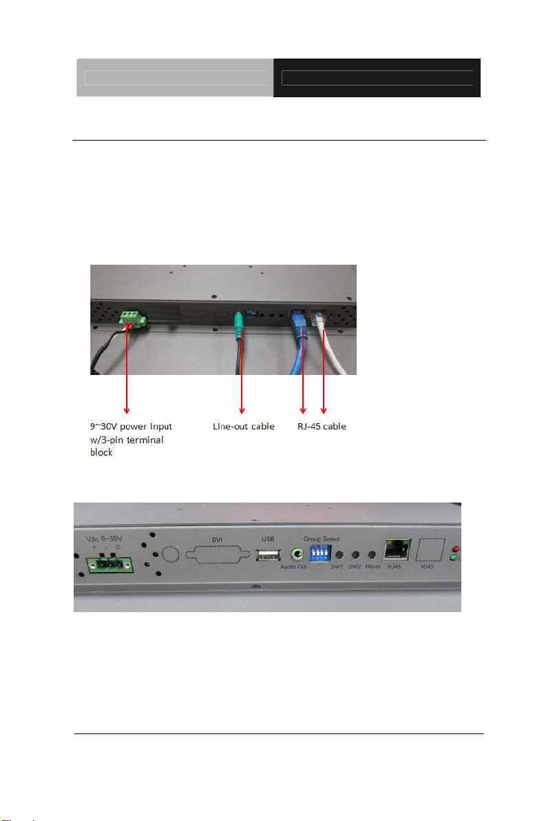
2.2 Connecting Power and Cables
To power on the LCD Display, use the provided AC-DC adapter and the
power cord to connect to the power output socket of the monitor. Fasten
the connector securely.
AGD-317R-A1
AGD-317R-A2
Chapter 2 Hardware Installation 2-3
Page 22

Remote Touch Display AGD-317R
2.3 Panel Mounting
This LCD Display can be placed on a shelf or table, or mounted onto the
wall. To mount it onto the wall, you need the mounting brackets, which you
will find them in the accessory box. Follow the steps described below:
Mount Bracket
Chapter 2 Hardware Installation 2-4
Page 23

Remote Touch Display AGD-317R
AGD-317R series can be mounted to the industrial standard 17" rack
directly. There are three screw holes on each side of the panel.
Analog Rackmount
2.4 Desktop, Swing-ARM Mounting
The AGD-317R series can be mounted in different ways. You can place
the desktop stand for desktop usage or attach it on a swing-arm bracket.
Desktop Stand
The brackets of desktop stand are attached to the rear of AGD-317R. First
of all, loosen the screw of point A. Then, unscrew the screw of point B. Pull
down the bracket and use the screw got from point A to fasten the
Chapter 2 Hardware Installation 2-5
bracket
Page 24

Remote Touch Display AGD-317R
in point B. There should be no screw in point A.
A
B
2.5 VESA Wall Mounting
Mounting the LCD Display with UL Listed Wallmount Bracket only. The
LCD Display can be mounted on a monitor arm or wallmount plate.
Caution:
When mounting the LCD Display, take care to tighten the
retention screws or bolts until fully secured, but do not over
tighten. Over tighting the retention screws or bolts may cause
them to become stripped, rendering them useless.
Chapter 2 Hardware Installation 2-6
Page 25

Remote Touch Display AGD-317R
Monitor Arm or Wallmount Plate Installation
The LCD Display has Video Electronics Standards Association (VESA)
standard mounting holes tapped into the rear panel. The standard holes
are M4 set at 100mm x 100mm apart.
VESA Mounting Holes
To mount the LCD Display onto a monitor arm or wallmount plate, please
follow the steps below.
Step 1: Line up the threaded holes on the monitor rear panel with
the screw holes on the monitor arm or wallmount plate.
Step 2: Secure the monitor to the arm or stand with the retention
screws supplied with the monitor arm or stand.
Chapter 2 Hardware Installation 2-7
Page 26

Remote Touch Display AGD-317R
2.6 LED Definitions
Red LED Green LED Condition
Off Power off
Static Static Link established
Static Flash Link in process
Flash Off Load firmware
2.7 Button Definitions
There are three buttons on remote gateway and display. Refer to the
following LED definitions.
AGD-317R-A1 (One-to-multiple Network)
SW1 SW2
Short Press
Long press on Reset
(Press until Red
LED blinking)
Chapter 2 Hardware Installation 2-8
Link on: Link (Default)
Link off: Unlink
Engineering Mode* N/A
Video Mode* (Default)
Graphic Mode*
Page 27

Remote Touch Display AGD-317R
Long Press on
Reset
(Press until both
Red LED and
Green LED Blinking)
If the application has different displays with different resolutions, you have
to push “Reset” and “SW1” for 1~3 seconds first and then release the
“Reset”. The red light will shine and then release the “SW1”. The
resolution of all displays will be set to the lowest solution.
Note: All of the displays has to be set in one resolution and it will be the
lowest resolution.
AGD-317R-A2 (One-to-one Network)
SW1 SW2
Short Press
Long press on
Reset (Press until
Red LED blinking)
Long Press on
Reset
(Press until both
Red LED and
Green LED Blinking)
Engineering
Mode* and
Reset to default*
Link on: Link (Default)
Video Mode* (Default)
Link off: Unlink
Engineering Mode* N/A
Engineering
Mode* and
Reset to default*
Update EDID*
Graphic Mode*
N/A
*1: Graphic mode:
The system will get better performance of graphic/text in the screen. But it
would occupy larger bandwidth of the network.
*2: Video mode:
The system will adjust automatically between Ethernet bandwidth and
video quality. It would occupy smaller bandwidth of the network.
Chapter 2 Hardware Installation 2-9
Page 28

Remote Touch Display AGD-317R
*3: Engineering mode:
(1)Static IP: 192.168.0.88
(2)User can connect to http://192.168.0.88 webpage for firmware
update.
(3) Firmware update file name will be: webfwc.bin
*4: Engineering mode:
(1) Reset Any change in SPI flash setup flag.
(2) Re-generate Random MAC to avoid any possible MAC collision.
After Reset to Default and reboot cycle, a new random MAC will be
generated.
*5: Update EDID:
The feature is used for one-to-multiple Mode to select which monitor/TV
EDID is used for system wide EDID usage. During one-to-multiple setup,
there may be monitor/TV that has lower resolution. For example, 1
monitor/TV with 720p resolution with mostly 1080p solutions. Please select
the monitor/TV with lowest resolution, to ensure all can be displayed
correctly. For customers who are using 1 pair of Host/Client with
one-to-multiple mode, the end user has to update EDID correctly. If not, it
will cause compatibility issues.
Operation:
The button event is triggered correctly at the remote display side, when
system is setup correctly for one-to-multiple. The selected EDID will be
update to Host Side EEPROM (HU7).
The same operation applies for Loopback EDID. In the system setup, the
last EDID updated will stay in the EEPROM. If customers setup this button
even many times, the last one triggered will be applied.
Chapter 2 Hardware Installation 2-10
Page 29

Remote Touch Display AGD-317R
2.8 DIP Switch
The function of DIP switch is to make ACG-203 and remote displays in one
group. When users want to send the data from specific ACG-203 to several
specific AGD-317R, they need to make the DIP switch of ACG and
AGD-317R to be the same.
Chapter 2 Hardware Installation 2-11
Page 30

Remote Touch Display AGD-317R
2.9 Connecting Power of Remote Display
To power on the LCD monitor, use the provided AC-DC adapter and the
power cord to connect to the power output socket of the monitor. Fasten
the connections securely.
A ”Surge Protection” device plugged between the AC-DC adapter and the
wall outlet is recommended to prevent the effects of sudden current
variations from reaching the LCD monitor. The sudden peaks of electricity
may harm the LCD monitor.
2.10 Connecting I/O Connectors of Remote Display
Turn off the computer and the LCD monitor before connecting them.
Use the RJ-45 CAT5/6 cable to connect to the RJ45 connector.
Connect USB devices to the USB connectors.
Chapter 2 Hardware Installation 2-12
Page 31

Remote Touch Display AGD-317R
2.11 Connecting Debugging
If the connection or display cannot work well, please refer to the debugging
steps below.
Make sure all of the cabling connected tightly
After the computer/display powers on, you will see the display is
reaching the local and remote IP below
Local IP: The IP address of the display
If the display cannot find the local IP as shown, it means the
network connection/cabling has some issues
Remote IP: The address of the remote box, such as ACG-203
or ACG-204
If the display cannot find the remote IP, it means the remote
box may have some issues, so the IP address in the remote
box cannot be found
Below is the situation, which is searching the IP address
If the display or sound cannot work properly, please try the following
step
Step1: Make sure the local and remote IP can be found. If the IP
address cannot be found, please check the network cabling
Step 2: Make sure the DVI/VGA and audio cable insert tightly
Chapter 2 Hardware Installation 2-13
Page 32

Remote Touch Display AGD-317R
2.12 The Matching of the Remote Box and Remote Display
A1 Display (One to Multi/ Cascade) has to work with ACG-203-A1
A2 Display (One to one) has to work with ACG-203-A2
If you did not use AAEON’s Remote Displays, you have to use ACG-204
series to work with non-AAEON displays. The PC will connect to
ACG-203 series and the ACG-203 series will connect to ACG-204 series
through RJ-45 cables.
Note:
ACG-203-A1 has to work with ACG-204-A1, and ACG-203-A2 has to
work with ACG-204-A 2
Chapter 2 Hardware Installation 2-14
Page 33

Remote Touch Display AGD-317R
On Screen
Display Control
Chapter
3
Chapter 3 On Screen Display Control 3-1
Page 34

Remote Touch Display AGD-317R
3.1 On Screen Display (OSD) Board Description
Buttons Description
Power Turn the monitor power ON or OFF.
Menu / Enter
UP / Right / Increase /
Input select
Down/ Left / Decrease
Auto
Activate the OSD menu.
Enter/confirm the selected option.
Move the selector to the next option.
Increase the gauge value of the
selected option.
Change input source.
Move the selector to the previous
option.
Decrease the gauge value of the
selected option.
Automatically adjust the clock,
phase, H-position and V-position.
Value to the most optimal settings.
Use full screen when enabling this
function.
Chapter 3 On Screen Display Control 3-2
Page 35

Remote Touch Display AGD-317R
3.2 OSD Main Menu: Push The MENU Keys
A vailable Key Functions
Power On/Off the LCD Monitor
or
or
or
or
Increase the gaguge value of the selected option
Decrease the gaguge value of the selected option
Slected to confirm
Return to last menu
Chapter 3 On Screen Display Control 3-3
Page 36

Remote Touch Display AGD-317R
3.3 Select Input Source
A vailable Key Functions
Power On/Off the LCD Monitor
or
or
or
or
Increase the gaguge value of the selected option
Decrease the gaguge value of the selected option
Slected to confirm
Return to last menu
Chapter 3 On Screen Display Control 3-4
Page 37

Remote Touch Display AGD-317R
3.4 Contrast/ Brightness- Submenu
A vailable Key Functions
Power On/Off the LCD Monitor
or
or
or
or
Increase the gaguge value of the selected option
Decrease the gaguge value of the selected option
Slected to confirm
Return to last menu
Chapter 3 On Screen Display Control 3-5
Page 38

Remote Touch Display AGD-317R
3.5 Geometry Menu
A vailable Key Functions
Power On/Off the LCD Monitor
or
or
or
or
Chapter 3 On Screen Display Control 3-6
Increase the gaguge value of the selected option
Decrease the gaguge value of the selected option
Slected to confirm
Return to last menu
Page 39

Remote Touch Display AGD-317R
3.6 Color Temperature- Submenu
A vailable Key Functions
Power On/Off the LCD Monitor
or
or
or
or
Increase the gaguge value of the selected option
Decrease the gaguge value of the selected option
Slected to confirm
Return to last menu
Chapter 3 On Screen Display Control 3-7
Page 40

Remote Touch Display AGD-317R
3.7 RGB Color- Submenu
A vailable Key Functions
Power On/Off the LCD Monitor
or
or
or
or
Chapter 3 On Screen Display Control 3-8
Increase the gaguge value of the selected option
Decrease the gaguge value of the selected option
Slected to confirm
Return to last menu
Page 41

Remote Touch Display AGD-317R
3.8 Language- Submenu
A vailable Key Functions
Power On/Off the LCD Monitor
or
or
or
or
Increase the gaguge value of the selected option
Decrease the gaguge value of the selected option
Slected to confirm
Return to last menu
Chapter 3 On Screen Display Control 3-9
Page 42

Remote Touch Display AGD-317R
3.9 Auto Config- Submenu
A vailable Key Functions
Power On/Off the LCD Monitor
or
or
or
or
Chapter 3 On Screen Display Control 3-10
Increase the gaguge value of the selected option
Decrease the gaguge value of the selected option
Slected to confirm
Return to last menu
Page 43

Remote Touch Display AGD-317R
3.10 Mode Resolution- Submenu
A vailable Key Functions
Power On/Off the LCD Monitor
or
or
or
or
Increase the gaguge value of the selected option
Decrease the gaguge value of the selected option
Slected to confirm
Return to last menu
Chapter 3 On Screen Display Control 3-11
Page 44

Remote Touch Display AGD-317R
3.11 Exit Menu- Submenu
A vailable Key Functions
Power On/Off the LCD Monitor
or
or
or
or
Increase the gaguge value of the selected option
Decrease the gaguge value of the selected option
Slected to confirm
Return to last menu
Chapter 3 On Screen Display Control 3-12
Page 45

Remote Touch Display AGD-317R
Chapter
4
Touch Screen
Driver Installation
Chapter 4 Touch Screen Driver Installation 4-1
Page 46

Remote Touch Display AGD-317R
4.1 Introduction
The optio na l AGD-317R Series touch screen uses 5-wire resistive
technology to provide more accurate sensing capacity than other
technologies. The touch screen is specially designed for tough
industrial environments, and has been approved by FCC Class A
standards.
Note: For A1 version, if you connect the RS-232 and USB touch
screen interfaces to the system simultaneously, the USB mode will
be the priority. For A2 version, the connection will be switched by
software.
Resistive T ype
Supply V oltage and Current
• +5 Vdc, nominal (+4.90 Vdc to +5.10Vdc) Self powered
only.
• 50 mA standby, typical at +5 Vdc; during touch 70 mA
average, 100 mA max
• Average power dissi pation is 0.5 W, typical.
• Supply must be capable of sourcing 100mA, max
• Total noise and ripple requirement must be less than 100
mV (p-p) for frequencies below 1 MHz, and less than
50 mV (p-p) for frequencies above 1 MHz.
Chapter 4 Touch Screen Driver Installation 4-2
Page 47

Remote Touch Display AGD-317R
Serial Interface
•
EIA 232E (Serial RS-232), DCE configuration. 8 Data
Bits, 1 Stop Bit, No Parity , Full Duplex.
• Hardware handshaking: RTS/CTS.
• DSR is pulled HIGH (>+3V) by the touch screen
control board when connected and powered. DTR can
be asserted by the host to interrupt the flow of data
from the controller. Note that if the application does not
monitor CTS, then an interval of approximately 5
seconds should be in se rted between the issuance of a
reset command and any other command.
Communication Parameters
• Baud Rate 9600 bps
• 8 Data bits, 1 stop bit, no parity only .
Interface - USB
Compliant to USB Revision 1.1. If the USB is connected to the
controller, the controller will communicate over the USB and not
over the serial port. However, the USB will never supply the
power to the touch screen control board. The touch screen
control board can be powered on automatically.
Chapter 4 Driver Installation 4-3
Page 48

Remote Touch Display AGD-317R
Operating Modes
Full T
ouch Smart Set protocol. Emulation of E281A-4002
protocol can be selected by Smart Set command.
Initial/ Stream/ Un touch/ Z-axis Enable Modes.
Touch Resolution: 2048 x 2048, size independent.
Conversion Time: Approximately 20 ms per coordinate set.
Chapter 4 Touch Screen Driver Installation 4-4
Page 49

Remote Touch Display AGD-317R
4.2 Resistive Touch screen Driver Installation
Hardware
Touch screen controllers must be configured for the driver prior to
installation. EETI typically ships controllers in a default setup that is
compatible with this driver. Controller requirements are:
Serial
Serial controllers must conform to these minimum requirements:
Baud rate : 9600 Baud
Data mat :
SMARTSET
It is desirable for a full handshaking connection to be established
between the touch screen controller and the computer, but it is not
required. The controller will function with this driver in a "two-wire,"
Receive Data and Ground (RxD and Gnd) co nfiguratio n. The
consequences of a two-wire connection are:
+ Automatic detection of the controllers on serial port s during setup
is not possible。
+ Controller information will not be registered in the Property Page
of the Control
Panel。
USB
* USB controllers require no configuration prior to installation.
*EETI
USB controllers are Human Interface Device (HID)
Chapter 4 Driver Installation 4-5
compliant.
Page 50

Remote Touch Display AGD-317R
The
Windows® XP and Wi ndows® 7 operating systems have native
HID drivers that provide low-level support for EETI touch screen
controller. An EETI touch monitor with a USB touch screen
controller installed will provide the following limited operation with
these native HID drivers. Operation of the controller will be limited
without the installation of the software discussed in the next
section:
The mouse cursor will move on the display in response
to touch
The direction of motion on the display will depend on the
orientation of the touch screen and the defaults programmed
into the controller
and the
driver
No "beep" will be heard when the screen is touched
No Control Panel application is available to configure the
operation of the driver .
Chapter 4 Touch Screen Driver Installation 4-6
Page 51

Remote Touch Display AGD-317R
4.3
Installing Driver for Windows
®
XP/ Windows® 7 / Linux
The touch screen has drivers for Windows® XP、 Windows® 7 and
Linux . You should read the instructions in this chapter carefully
before you attempt installation.
Note 1: The following windows illustrations are examples only . You
must follow the flow chart instructions and pay attention to the
instructions which then appear on your screen.
Note 2: Please make sure the OS of your computer support Windows®
XP/ Windows® 7 while installing Windows® XP/ Windows® 7 drivers in the
CD-ROM to the system.
For Windows
®
XP OS, please execute:
CD-ROM:
\\TouchScreen-DRV\eGalax Touch \Win XP\Setup.exe
ck on the “Next” button on
1. Cli
the
Welcome
window screen
Chapter 4 Driver Installation 4-7
Page 52

Remote Touch Display AGD-317R
2. Click the “Nex
t” button on
the
screen
3. Click on the “Finish” button a nd r estart your
system
Single monitor, Serial Port controller
The driver files will install automatically. When the "Setup
Complete" screen appears, you may choose to run calibration
immediately or later. If you choose not to run this program now, you
can run it from the EETI Control Panel application.
Chapter 4 Touch Screen Driver Installation 4-8
Page 53

Remote Touch Display AGD-317R
1. Executing eGal
ax on Desktop
2.
Recognition devices choose to run calibration immediately
Chapter 4 Driver Installation 4-9
Page 54

Remote Touch Display AGD-317R
3. Choose To
ols to calibrate
4. Click on 4 Points Calibration to execute calibration
: If the alignments do not match display by 4 Points Calibration, please
Note
use 9 Ports or more to calibrate.
Chapter 4 Touch Screen Driver Installation 4-10
Page 55

Remote Touch Display AGD-317R
For Windows
®
7 OS please execute:
CD-ROM:
\\TouchScreen-DRV\eGalax Touch \Win 7 \Setup.exe
1. Cli
ck on the “Next” button
2. Click on the “Next” button
Chapter 4 Driver Installation 4-11
Page 56

Remote Touch Display AGD-317R
3. Tick “Non
reboot. Click on the “Next” button
e” if the system did not start 4 points calibrating after
.
4. Tick “Support Multi-Monitor System,” and click o n the “Next”
button
Chapter 4 Touch Screen Driver Installation 4-12
Page 57

Remote Touch Display AGD-317R
5. Select Destination F
older, and click on the “Next” button
6. Click on the “Next” button
Single monitor, Serial Port controller
The driver files will install automatically. When the "Setup
Compl
ete" screen appears, you may choose to run
calibration immediately or later. If you choose not to run this
program now, you can run it from the EETI Control Panel
application.
Chapter 4 Driver Installation 4-13
Page 58

Remote Touch Display AGD-317R
1. Executing eGal
ax on Desktop
2. Recognition devices choose to run calibration immediately
Chapter 4 Touch Screen Driver Installation 4-14
Page 59

Remote Touch Display AGD-317R
3. Choose To
ols to run calibration
4. Click on 4 Points Calibration to execute calibration
Note: If the alignments do not match display by 4 Points Calibration, please
use 9 Ports or more to calibrate.
Chapter 4 Driver Installation 4-15
Page 60

Remote Touch Display AGD-317R
For Linux Fedora 14 kernel 2.6.35.6-45.fc14 OS please execute:
CD
-ROM:
\\TouchScreen-DRV\eGalax Touch \Linux\eGalaxTouch 32
1.
Open System Input Command (su) and System Password
2. Input command ( Xorg : l –configure)
Chapter 4 Touch Screen Driver Installation 4-16
Page 61

Remote Touch Display AGD-317R
Input command ( cp /root/xorg.conf.new /etc/X11/xorg.conf)
3.
4. Load Linux Folder Touch Driver
Chapter 4 Driver Installation 4-17
Page 62

Remote Touch Display AGD-317R
5. Executive Touch Driver
6. Which interface controller do you use?
Chapter 4 Touch Screen Driver Installation 4-18
Page 63

Remote Touch Display AGD-317R
7. Select the “ 3 ” USB inte
rface. (Select the USB interface and
press “Enter” key of the keyboard to start the installation)
8. Select the “1” COM interface (Select the COM interface and
press the “Enter” key of the keyboard to start the installation)
Chapter 4 Driver Installation 4-19
Page 64

Remote Touch Display AGD-317R
9. Execute reboot
10. Select the X86 Folder (Because Linux is 32 bit)
Chapter 4 Touch Screen Driver Installation 4-20
Page 65

Remote Touch Display AGD-317R
11. Select “e
Galax Touch32_Version1.1-2.6X” Folder
12. Select “eGalax Touch32” Folder
Chapter 4 Driver Installation 4-21
Page 66

Remote Touch Display AGD-317R
13. Click on the “eG
alax Touch” to calibrate immediately
14. Choose “Tool” to calibrate
Chapter 4 Touch Screen Driver Installation 4-22
Page 67

Remote Touch Display AGD-317R
15. Execute 4 Points Calibration
Note: If the alignments do not match display by 4 Points Calibration, please
use 9 Ports or more to calibrate.
16. Draw and test (Drawing、Writing)
Chapter 4 Driver Installation 4-23
Page 68

Remote Touch Display AGD-317R
17. If you are going to replace the Interface, please remove the old
Touch Driver
18. Reboot
(Input command: sh setup.sh uninstall)
Chapter 4 Touch Screen Driver Installation 4-24
 Loading...