

Page 1

3
Carbon Monoxide Monitor and
Retrofit Carbon Monoxide Monitor
Kit W -2808/37027
User Instructions
(Keep these instructions for reference)
Page 2

Page 3

i
English
TABLE OF CONTENTS
GENERAL SAFETY INFORMATION 2
– Intended Use 2
– List of Warnings and Cautions within these User Instructions 2
USE INSTRUCTIONS AND LIMITATIONS 3
– Use For 3
– Do Not Use For 3
– General Description 3
SPECIFICATIONS 6
PRODUCTS,ACCESSORIES AND P AR TS 7
– 3MTMCarbon Monoxide Monitor 7
– 3MTMRetrofit Carbon Monoxide Monitor Kit W-2808/37027 7
– 3MTMAccessories and Parts 7
ASSEMBLY 8
SET UP PROCEDURES AND PERFORMANCE CHECK 10
– Monitor Calibration Frequency 10
OPERATING INSTRUCTIONS 11
– Normal Operation 11
– Calibration 12
REPLACEMENT PART INSTRUCTIONS 13
– Batteries 13
– 3M
TM
Carbon Monoxide Sensor 529-05-22 13
TROUBLESHOO TING 15
IMPORTANT NOTICE 17
– W arranty 17
– Remedy 17
FOR MORE INFORMATION 18
Page 4

2
GENERAL SAFETY INFORMATION
Intended Use
The 3MTMCarbon Monoxide (CO) Monitor and the 3MTMRetrofit Carbon Monoxide (CO)
Monitor Kit are designed to provide continuous, direct read CO monitoring for compressed
air used with supplied air respirators.
List of Warnings and Cautions within these User Instructions
• These products are designed for carbon monoxide monitoring. Misuse may result in
sickness or death. For proper use, see supervisor or User Instructions, or call 3M in U.S.A.,
1-800-243-4630. In Canada, call Technical Service at 1-800-267-4414.
• The impedance of any connected load device at the REM ALARM (remote alarm) jack must
be greater or equal to 12 ohms, when operating from internal batteries or AC adapter. Failure
to do so may damage the carbon monoxide monitor and result in sickness or death.
• The intrinsic safety of the carbon monoxide monitor is voided when remote alarm is used.
• The intrinsic safety of the carbon monoxide monitor is voided when the 110-120 volt AC
adapter is used.
• Your employer must provide breathing air that meets at least the requirements of the
specification for Grade D breathing air, as described in the Compressed Gas Association
Commodity Specification G-7.1-1997 in the United States. In Canada refer to CSA standard
Z180.1, for the quality of the compressed breathing air. Failure to do so may result in
sickness or death.
• Use of equipment described in these User Instructions must be in accordance with applicable
health and safety standards, or pursuant to the recommendations of an industrial hygienist.
• Each person using this equipment must read and understand the information in these User
Instructions. Use of this equipment by untrained or unqualified persons, or use that is not
in accordance with these User Instructions, may adversely affect product performance and
result in sickness or death.
W WARNING
CAUTION:
• Observe proper polarity when inserting batteries. Polarity is marked on the inside of the drawers.
• The sensor in the carbon monoxide monitor contains a small amount of sulfuric acid. Always
wash hands thoroughly after handling sensor cell. Sulfuric acid is poisonous and can cause
severe burns. Do not allow acid to contact skin or eyes. If eyes are exposed to acid, flush
thoroughly and seek immediate medical attention.
Page 5
3
English
USE INSTRUCTIONS AND LIMITATIONS
Important
Before use, each person using this equipment must read and understand these User Instructions.
Keep these instructions for reference.
Use For
Monitoring for carbon monoxide level in compressed air intended for respiratory protection systems.
Do Not Use For
Monitoring other compressed gas streams.
General Description
These User Instructions apply to the 3MTMCO Monitor mounted inside some of the 3MTMPortable
Compressed Air Filter and Regulator Panels and the 3M
TM
Retrofit CO Monitor Kit W-2808/37027.
The retrofit kit includes the 3M CO monitor and accessories to attach the CO monitor to a
3
/
8
-inch
port on a filter and regulator panel that does not currently have CO monitoring capability, such as
the 3M
TM
Compressed Air Filter and Regulator Panel W-2806/07006.
The 3M carbon monoxide monitor is designed to provide continuous, direct read CO monitoring
for compressed air used with supplied air respirators. An internal microprocessor controls the
indication and alarm functions in response to the signals of an electrochemical CO sensor. It
continuously monitors a compressed air sample introduced to its sensor at an approximate rate
of 1.0 standard cubic foot per hour (scfh) and gives an alarm when the CO in the sample reaches
a preset level (10 ppm in USA; 5 ppm in Canada).
The CO monitor is a battery powered unit utilizing two 9 volt alkaline batteries. It is designed to
be intrinsically safe when used on battery power. The CO monitor is CSA certified intrinsically
safe for Class I, Div. I, Groups A,B,C, and D Hazardous Locations when utilizing two 9 volt
alkaline batteries to power the monitor.
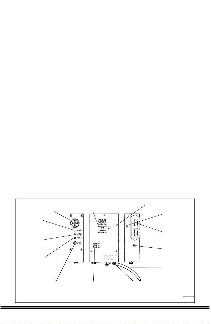
The components of the monitor are assembled into a black powder-coated aluminum housing
6˝ H x 4˝ W x 2˝ D overall. A hose barb, with plastic sample tube attached for introducing the
sample gas, extends from the bottom. Available at the front face are the OFF/ON/TEST switch,
the display (LCD), SPAN and ZERO adjustments.
The left side contains the indicating lights, the alarm buzzer, and the remote alarm jack.
Accessible on the right side are the two battery drawers and the auxiliary power jack. (Fig. 1)
Buzzer - Provides continuous tone
during high “CO” alarm; a pulsing tone
during certain malfunction conditions.
Display - LCD type refreshed
every 0.8 seconds; the red LED
light faintly blinks at same time.
Span & zero potentiometers
used in calibrating.
Screw sealed
access hole to
alarm level
potentiometer.
“Transistor”
type battery
holders
Auxiliary “power
source” jack
Air sample tube
Remove knurl thumbscrews for
access to “CO” sensor. Bottom pla te
sensor/sample tube assembly. Can be
moved approx. 2-3˝ before sensor wire
connections limit travel.
On/Off/Test switch-three
position type. Alternate
on-off position with
momentary “test”
position.
Remote alarm jack; for
plugging remote alarm
devices or relays to be
energized when monitor
goes into alarm.
Green normal LED
light; comes on steady
when monitor on &
goes off in alarm
conditions.
Yellow low battery
LED light; comes on
when 9 volt battery
voltage falls below
about 7.0 volts.
Red alarm, LED light;
blinks faintly during
normal operations
& on steady during
high “CO” alarm
conditions.
Fig. 1
Page 6

4
The impedance of any connected load device at the REM ALARM (remote alarm) jack must be
greater or equal to 12 ohms, when operating from internal batteries or AC adapter. Failure to do
so may damage the carbon monoxide monitor and result in sickness or death.
W WARNING
Front Panel On/Off/Test Switch
This switch is a three-position type with alternate ON and OFF positions, and a momentary
TEST position. Switch is located at the lower left side.
Display
Display is a centrally located LCD type and is refreshed every 0.8 seconds; the red ALARM
light faintly blinks at the same time.
Span and Zero Adjustments
Located to the right of the display are two miniature multi-turn slotted-shaft potentiometers,
accessible through holes in the panel with a small screwdriver.
Left Side
The next five items are aligned toward the rear from the center of the left side panel and from
top to bottom are:
Buzzer
Buzzer is at the top of the side panel. It provides a continuous tone during high CO alarm,
a pulsing tone during certain malfunction conditions.
Alarm Light
Red ALARM light blinks faintly during normal operation and is on steadily during the high CO
alarm condition.
Low Battery Light
Yellow LOW BATTERY light comes on when battery voltage falls to where the instrument
will not function properly (about 7 volts DC). Batteries should be replaced at this time.
Normal Light
The green NORMAL light acts as a pilot light and glows when the instrument is turned on.
At the same time the red ALARM light flickers faintly at intervals of about one second.
Remote Alarm (REM ALARM)
A miniature size phone jack is provided for plugging in a remote alarm device so that the alarm
sound can be repeated at a distance from the instrument. The outer shell of the jack is grounded to
the case, and is negative. This jack will be energized at voltage about 8.5 volts DC when operating
from “fresh” internal batteries or about 8.9 volts DC when operating from AC adapter whenever
instrument is in alarm condition.
Page 7

5
English
Bottom
A rectangular opening in the bottom allows clearance for the sensor that is mounted to the upper
face of the bottom plate. The bottom plate is held in place by two knurled thumbscrews. The
sample inlet fitting and tubing extends from the outer face of the bottom plate.
Right Side
These items are aligned toward the rear of the right side panel.
There are two battery compartment drawers near the top. They contain the two 9 volt alkaline
batteries, connected in parallel, which power the instrument.
Auxiliary Power Jack
A 2.5 mm pin jack is located near the bottom for operating the instrument from the AC adapter.
The AC adapter will power the instrument as long as power is supplied to it. The outer shell of
the jack is grounded to the case and is negative.
Page 8

6
SPECIFICATIONS
Sensor – Electrochemical/CO specific
Readout – Direct read LCD
Range – 0-199 ppm
Alarm – 85 dBA at 10 ppm CO (5 ppm Canada)
Sensor Life – Approximately 30 months
Sensor Replacement – User allowed to replace sensor
Intrinsic Safety – Class I, Div I, Group A, B, C, D (when operated
on battery power)
Power – 9 volt DC alkaline batteries (2 each)
Aux. Alarm Output – Maximum output current draw is 300 milliampere
Aux. Power Sources – 120 volt AC - 7.5 volt DC adapter
Operating Temperature Range – 0-110º F (17-43º C) (ambient temperature)
• The impedance of any connected load device at the REM ALARM (Remote Alarm) jack
must be greater or equal to 12 ohms, when operating from internal batteries or AC adapter.
Failure to do so may damage the carbon monoxide monitor and result in sickness or death.
• The intrinsic safety of the carbon monoxide monitor is voided when remote alarm is used.
• The intrinsic safety of the carbon monoxide monitor is voided when the 110-120 volt AC
adapter is used.
W WARNING
Page 9

7
English
PRODUCTS,ACCESSORIES AND PAR TS
3MTMCarbon Monoxide Monitor
The 3M CO monitor is factory mounted inside some of the 3MTMPortable Compressed Air Filter
and Regulator Panels. Consult the User Instructions for your 3M
TM
Portable Compressed Air
Filter and Regulator Panel.
3MTMRetrofit Carbon Monoxide Monitor Kit W-2808/37027*
The 3M retrofit kit allows the 3M CO monitor to be used with filter and regulator panels that do not
currently have CO monitoring capability, such as the 3M compressed air filter and regulator panel
W-2806/07006*. The 3M retrofit CO monitor kit is comprised of a 3M CO monitor, mounting
bracket, flow meter, and hardware connections to attach the monitor to an available
3
/
8
-inch port
on a filter and regulator panel.
* 37027 is an automotive product number for W-2808.
* 07006 is an automotive product number for W-2806.
3MTMAccessories and Parts
3M
TM
Adapter, 110-120 Volt AC (for CO Monitor)
This accessory will supply operating power to the instrument as long as it is plugged into an active
115 volt AC outlet, whether or not batteries are installed. The adapter will convert the 115 volt AC
to 7.5 volt DC, 650 mA.
1. Plug the adapter into an active, fused (1 amp) 115 volt 50/60 Hz outlet.
Note: To prevent unnecessary electrical interference, the outlet should be on a dedicated circuit
free of any intermittent heavy electrical loads, such as pumps, compressors or heaters.
2. Plug adapter cord connector into socket on the lower right-hand side of the monitor.
3. Adapter will power the instrument as long as the 115 volt AC source remains active.
4. Since the adapter voltage is slightly higher than that of the internal batteries, the adapter
will supply the power. Blocking diodes protect the internal interface.
529-04-49 Calibration Kit, Small
529-04-48 Calibration Kit, Large
529-04-50 Adapter, 110-120 Volt
529-05-18 Zero Gas Cylinder, 0.6
cubic feet of gas
(replacement Zero gas
for small kit, 529-04-49 )
529-05-19 Span Gas Cylinder, 0.6
cubic feet of gas
(replacement Span gas
for small kit, 529-05-49)
529-05-17 Zero Gas Cylinder, 3.6
cubic feet of gas
(replacement Zero gas
for large kit, 529-04-48 )
529-05-16 Span Gas Cylinder, 3.6
cubic feet of gas
(replacement Span gas
for large kit, 529-04-48)
529-05-20 Remote Alarm Audible,
119 dBA
529-05-21 Remote Alarm, Strobe
Light, 150,000 CP
(Requires 529-04-50)
529-05-23 Y-Plug Adapter
529-05-22 Carbon Monoxide Sensor
The intrinsic safety of the carbon monoxide monitor is voided when the 110-120 volt AC
adapter is used.
W WARNING
Page 10

8
ASSEMBLY
The following instructions apply only if you are using the 3MTMRetrofit CO Monitor Kit
W-2808/37027. (Fig. 2 and 3)
1. Secure the mounting bracket to a surface close to the filter and regulator panel with #8 x
1
/
2
˝
self tapping screws.
2. Secure the monitor to the mounting bracket with #6-32 x
1
/
2
˝ screws and #6 lock washers.
Screw holes are located on the left side of the monitor.
3. The CO monitor is supplied with a 2-foot sample tube attached to the hose barb located on the
monitor’s bottom plate.
4. Use the supplied 90° st. elbow, 2
1
/
2
˝ pipe nipple, and
3
/
8
˝ x
1
/
8
˝ reducing bushing to connect
the bottom of the flow meter to an available port, just prior to the compressed hose
connections, on the filter and regulator panel. If you are installing the flow meter on the 3M
compressed air filter and regulator panel W-2806/07006, you will need to remove the plug
from the CO sampling port located above the quick disconnect outlets on the panel.
Note: If your panel is wall-mounted, you may have to remove the panel from the wall to attach
the flow meter.
6. Pull up the black tube lock collar at the top of the flow meter and insert the free end of the
plastic sample tube. Push down on the lock collar to secure the sample tube.
C
A
R
B
O
N
M
O
N
O
X
ID
E
T
E
S
T
O
N
O
F
F
1
12
11
10
9
8
7
6
5
4
3
2
13
Fig. 2
Page 11

English
9
Assembled 3MTMRetrofit Kit W-2808/37027 attached to 3MTMCompressed Air Filter and Regulator
Panel W-2806/07006 (sold separately).
Item Product Description Quantity
Number Number Required
1 --- CO monitor 1
2 --- #6-32 x
1
/
2
˝ screw 4
3 --- #6 lock washer 4
4 --- #8 x
1
/
2
˝ self tapping screw 4
5 --- Mounting bracket 1
6 --- 2-foot sample tube 1
7 --- Tube lock collar 1
8 --- Flow meter 1
9 --- 90º st. elbow 1
10 --- 2-
1
/
2
˝ pipe nipple 1
11 ---
3
/
8
˝ x
1
/
8
˝ reducing bushing 1
12 W-2808/37027 3M
TM
Retrofit CO Monitor Kit-includes items 1-11
13 W-2806/07006 3M
TM
Compressed Air Filter and Regulator Panel (Sold
Separately)
CARBON
MONOXIDE
SPAN
TEST
ON
OFF
ZERO
Fig. 3
Page 12

10
SET UP PROCEDURES AND PERFORMANCE CHECK
1. Turn instrument on and allow 5 minutes to stabilize. Verify that the yellow LOW BATTERY
light is off.
2. Push up and hold switch in the test position.
– The red ALARM light will come on verifying the CO alarm circuit operation.
– The yellow LOW BATTERY light will also come on, verifying the low battery detection circuit.
– Green NORMAL light will blink several times, then come on steady verifying continuity of
the detector circuits.
– The buzzer will sound and the REM ALARM jack will be energized.
– The display will show an upscale reading.
– Release the switch. Indicators will return to normal and display may first show a negative
indication (-XX), then return close to 00.
3. Remove the plastic sample tube from the black tube lock collar on top of the flow meter.
Introduce a sample of zero air to the sample tube (see User Instructions for the 3M
TM
Calibration Kit 529-04-48 or 529-04-49). The sample flow should be between 0.5 and 1.5 scfh.
4. Verify that the green NORMAL light is on, the red ALARM light is flickering about once a
second and the display is showing 00 (zero), (see Calibration and Adjustment section of this
User Instruction).
5. Remove the zero air sample and introduce a known sample of 50 to 150 ppm CO to the
sample inlet tube (see User Instructions for the 3M
TM
Calibration Kit 529-04-48 or 529-04-49).
The sample flow should be between 0.5 and 1.5 scfh.
6. Verify that the display readings rise upscale and the alarm light and buzzer operate (see
Calibration and Adjustment section of this User Instruction).
7. Remove the CO sample.
8. Reconnect the sample tube to the black tube lock collar on top of the flow meter.
9. After adjusting the regulator on the air purification panel to the proper setting for your
respiratory protection, adjust the flow meter knob so that the black floating ball is within the
green boxed area etched on the flow meter body. Counterclockwise rotation of flow meter’s
knob will increase sample airflow to the monitor.
10. Instrument is now ready for normal use. Turn OFF when not in use.
Monitor Calibration Frequency
The CO monitor should be calibrated prior to use and every two weeks for the first month. After
the first month, calibrate the monitor monthly if it is used on a continuous basis (daily or weekly).
If the monitor is used on a non-continuous basis the monitor should be calibrated prior to each use.
Note: If monitor's alarm is energized, always check calibration to be sure monitor is not
malfunctioning and/or out of calibration producing a false alarm/reading.
Page 13

English
11
OPERATING INSTRUCTIONS
The following instructions are intended to serve as a guideline for the use of the 3MTMCarbon
Monoxide Monitor. It is not to be considered all-inclusive, nor is it intended to replace the policy
and procedures for each facility.
If you have any doubts about the applicability of the equipment to your job situation, consult an
industrial hygienist or call 3M's Occupational Health and Environmental Safety Division Technical
Service Department 1-800-243-4630. In Canada, call Technical Service at 1-800-267-4414.
Normal Operation
– The monitor will analyze the compressed air and show CO content on the display, in parts per
million (ppm).
– The green NORMAL light will glow continuously and the red ALARM light will flicker about
every second.
– When the CO concentration reaches the alarm point (10 ppm for USA, 5 ppm for Canada) the
red ALARM light will come on steady, the green NORMAL light will go off, the buzzer will
sound a steady tone, and the REM ALARM jack will be energized.
– When the CO concentration drops below the alarm setting, the indicators will automatically
return to normal.
• Your employer must provide breathing air that meets at least the requirements of the
specification for Grade D breathing air, as described in the Compressed Gas Association
Commodity Specification G-7.1-1997 in the United States. In Canada refer to CSA
standard Z180.1, for the quality of the compressed breathing air. Failure to do so may
result in sickness or death.
• Use of equipment described in these User Instructions must be in accordance with
applicable health and safety standards, or pursuant to the recommendations of an
industrial hygienist.
• Each person using this equipment must read and understand the information in these
User Instructions before use. Use of this equipment by untrained or unqualified persons,
or use that is not in accordance with these User Instructions, may adversely affect product
performance and result in sickness or death.
W WARNING
Page 14

12
Calibration
Calibrate the monitor in the temperature range in which it will be used. After each adjustment
in the following steps, allow time for the changes to stabilize. Recheck all adjustments. Turn
monitor on and allow at least 5 minutes warm-up before calibration and adjustments are made.
Zero Adjustment
Remove sample tube from the black tube lock collar on top of the flow meter. Introduce a sample
of zero air to the sample tube (see User Instructions for the 3M
TM
Calibration Kit 529-04-48 or
529-04-49). The sample flow should be between 0.5 and 1.5 scfh.
Verify that the green NORMAL light is on, the red ALARM light is flickering about once a second
and the display is showing “00”. If the display is showing other than “00”, adjust the ZERO
potentiometer (next to the display) so that the reading is “00”. Clockwise adjustment increases
reading. Notice that the display jumps from 00 to +02 or to –02 (monitor does not display –01 or
+01). Try to set the potentiometer midway between the two extremes. Remove the zero air sample.
Span Adjustment
Introduce a known sample of 50 to 150 ppm CO to the sample tube (see User Instructions for the
3M
TM
Calibration Kit 529-04-48 or 529-04-49). The sample flow should be between 0.5 to 1.5 scfh.
Verify that the green NORMAL light is off, the red ALARM light is on full bright and the
stabilized reading, after approximately one minute, is equal to the known concentration of CO.
If the display is showing a difference, adjust the SPAN potentiometer (next to the display) to
obtain proper value. Turn clockwise to increase reading. If the span adjustment cannot be made
as indicated, the sensor needs to be replaced; make sure this is not happening due to an empty
span gas cylinder. See Replacement Part section of this User Instruction.
Remove the known sample of CO and reconnect the sample tube to the black tube lock
collar on top of the flow meter. The instrument is now properly adjusted for use.
Page 15

English
13
REPLACEMENT PART INSTRUCTIONS
Batteries
Check batteries each time instrument is turned on by noting that the green NORMAL light is on
and the yellow LOW BATTERY light is off. If the yellow light is on, the batteries need replacing.
Two 9 volt alkaline batteries will power the monitor continuously for approximately 30-35 hours.
Batteries are contained in drawers on the right-hand side.
To replace the batteries:
Pull the small slot in the drawer face toward the front of the monitor to unlatch the drawer and pull
the drawer out of the housing.
Pry battery out of drawer with fingers and replace with a fresh 9 volt alkaline battery, providing for
proper polarity by placing minus (-) terminal uppermost in holder. Place bottom of fresh battery
against spring and press into place.
CAUTION:
Observe proper polarity when inserting batteries. Polarity is marked on the inside of the drawers.
Push drawer back into housing until it latches in place. Drawers inserted incorrectly will not latch.
Repeat above steps for the second battery. (It is possible to operate with only one battery, but
operating hours will be greatly reduced).
3MTMCarbon Monoxide Sensor 529-05-22
To replace sensor: (Fig. 4)
Remove the two knurled thumbscrews at bottom.
Pull the bottom plate off the housing as far as the wiring will allow.
Remove the 2 screws holding the wire connectors’circuit board/sensor cell in flow block.
An o-ring is located under the sensor at the bottom of the flow block cavity – DO NOT LOSE.
Pull the wire connectors’ circuit board from the sensors’ pins carefully so as not to damage the
circuit board.
Discard old sensor cell. It contains a small amount of sulfuric acid. Dispose of sensor according
to local regulations.
CAUTION:
The sensor in the carbon monoxide monitor contains a small amount of sulfuric acid. Always wash
hands thoroughly after handling sensor cell. Sulfuric acid is poisonous and can cause severe burns.
Do not allow acid to contact skin or eyes. If eyes are exposed to acid, flush thoroughly and seek
immediate medical attention.
The wire connectors’ circuit board relates to the 3 pins on the sensor as shown in figure 4. The
fourth pin is used as a guide pin to install circuit board to sensor. Carefully press circuit board
evenly on sensors’4 pins. New sensors have a shorting wire/spring between the sensing and
reference pins, remove and discard.
Page 16

14
Wire Color Detector Terminal
Black CNTR
Blue REF
Red SENSING
Be sure flow block cavity and o-ring are dry
and clean of oils, dirt etc. The o-ring must be
positioned evenly in the bottom of the flow
block cavity. Push the sensor into block against
o-ring and evenly tighten the 2 screws that hold
the circuit board/sensor to flow block. Tighten
screws lightly to assure good seal with o-ring.
Do not overtighten screws or damage to circuit
board/sensor may occur.
Replace the bottom plate and secure it
with thumbscrews.
Make sure the inlet sample swivel elbow
is firmly tightened.
Allow at least one hour for stabilization,
then calibrate as in Calibration and Adjustment
section of this User Instruction.
Fig. 4
Circuit board/
sensor to flow
block mounting
screws.
Wire connectors’
circuit board
“CO” sensor cell
O-ring
Flow block
Page 17

English
15
CO monitor’s LED red and
green lights blink on/off
along with the alarm buzzer
and display shows 'SC'
The sensor has internal failure
Poor connection between
sensor pins and circuit
board connections
Turn monitor off and after
a few seconds turn monitor
back on. Try to calibrate the
monitor. If the monitor will
not calibrate, replace the sensor.
Unplug-Plug circuit board
from sensor pins to make
better contact connection.
Try to calibrate monitor.
If monitor will not calibrate
or ‘SC’appears again,
replace sensor.
TROUBLESHOO TING
Low battery
As the battery voltage declines toward the end of its life, the following indications occur:
a) At 7.0 volts, the amber LOW BATTERY light will come on. Battery replacement is
recommended at this point, but continued operation is still possible.
b) At 6.4 volts, the buzzer will beep at intervals of about 7 seconds.
c) At 5.8 volts, the buzzer will beep at 1-second intervals and the display will go to --.
This malfunction indication will continue until the battery is completely dead.
CO monitor display will not
move from zero ‘00’when
the sensor is exposed to a
known sample of CO
SPAN adjustment may
be set to zero
Span gas cylinder empty
The sensor has lost sensitivity
Circuit malfunction
Recalibrate the monitor
Replace the cylinder
Replace the sensor
Repair is needed
The CO monitor cannot
be calibrated
The span gas and/or zero
gas bottle(s) may be empty
The sensor has lost sensitivity
Replace the empty span
and/or zero gas bottle(s)
Replace the sensor
Problem Potential Cause Corrective Action
The span adjustment cannot
be made when the span gas is
applied (i.e. the reading will
not reach the span gas value)
The span gas bottle may
be empty
The sensor has lost sensitivity
Replace the empty span
gas bottle
Replace the sensor
With zero gas flowing
through the monitor after
approximately one-minute
display reads minus one
(-1) to the far left
Zero potentiometer may be
turned counter
clockwise all
the way
The sensor has lost sensitivity
Adjust the zero potentiometer
c
lockwise until zero
‘00’ reached
Replace the sensor
Page 18

16
With span gas flowing
through the monitor after
approximately one-minute
display reads one (1) to the
far left
Span potentiometer may be
turned c
lockwise all the way
The sensor has lost sensitivity
Adjust the zero potentiometer
counter
clockwise to 199 and
then turn down to value of
span gas
Replace the sensor
When calibrating the CO
monitor you cannot move
display off zero '00' with
zero potentiometer
Monitor may have been
adjusted ‘00’ using the
span potentiometer
Turn the span potentiometer
screw several full revolutions
c
lockwise until the display
reads the value of the span
gas then start the calibration
procedure over again
Display goes below 0 (i.e.
display indicates a –02,
-1, SC)
Zero misadjust
Sensor has internal failure
Circuit malfunction
Recalibrate the monitor
Replace the sensor
Repair is needed
Problem Potential Cause Corrective Action
Monitor display
numbers wander and
alarm periodically
Monitor is powered by the
110-120 volt AC adapter and
walkie-talkies are being used
near the monitor
Large voltage spikes are
present in the AC circuit
Ambient temperatures exceed
110º F (43º C)
Do not use walkie-talkies
in the area
Isolate by using dedicated line
Decrease ambient temperature
Page 19

English
17
IMPORTANT NOTICE
W arranty
3M warrants its Carbon Monoxide Monitor for a period of one (1) year and its Carbon Monoxide
Sensor for a period of two (2) years from the original shipping date, to be free from defects in
material and workmanship in normal service and under normal conditions. This warranty is void if
the Carbon Monoxide Monitor or Carbon Monoxide Sensor has been damaged by accident, misuse,
neglect, improper service, or other causes not arising out of defects in material or workmanship.
This warranty does not include replaceable items, such as filter elements, which are considered part
of a regular maintenance program. Any implied warranties arising out of the sale of 3M’s Carbon
Monoxide Monitor and its Carbon Monoxide Sensor, including but not limited to the implied
warranties of merchantability and fitness for a particular purpose, are limited in duration to the
above one (1) and two (2) year periods respectively. 3M shall not be liable for loss of use of
any of its products or incidental or consequential costs, expenses, or damages incurred by the
purchaser or any other user.
THE FOREGOING WARRANTY IS EXCLUSIVE AND IS IN LIEU OF ALL OTHER
WARRANTIES EXPRESS, IMPLIED, OR STATUTORY, INCLUDING WARRANTY OF
MERCHANTABILITY.
Remedy
Should the Carbon Monoxide Monitor or the Carbon Monoxide Sensor fail in normal service
under normal conditions through no fault of the purchaser or any other user during the warranty
period, return the Carbon Monoxide Monitor or Carbon Monoxide Sensor to a 3M authorized
warranty repair service center. No charges will be made for repair or replacement. Each
repaired unit is warranted for sixty (60) days or the remaining portion of the original equipment’s
warranty, whichever is longer. THE FOREGOING CONSTITUTES THE SOLE AND
EXCLUSIVE REMEDY AND IS IN LIEU OF ANY AND ALL OTHER REMEDIES
WHICH MAY BE AVAILABLE.
This warranty becomes void immediately should any repair of or alterations to the warranted
equipment be made without authorization by 3M.
Page 20

© 3M 2003
38-9018-0147-2
3
3M Occupational Health and
Environmental Safety Division
3M Center, Building 235-2W-70
P.O. Box 33010
St. Paul, MN 55133-3010
3M Occupational Health and
Environmental Safety Division
3M Canada Company
P.O. Box 5757
London, Ontario N6A 4T1
FOR MORE INFORMATION
In United States, contact:
Internet: www.3M.com/occsafety
Technical Assistance: 1-800-243-4630
For other 3M products:
1-800-3M-HELPS or 1-651-737-6501
In Canada, contact:
Internet: www.3M.com/CA/occsafety
Technical Assistance: 1-800-267-4414
For other 3M products:
1-800-364-3577
 Loading...