

Page 1

Service Instructions
Important Safety
Information
BEFORE INSTALLING
OR OPERATING THIS
™
3M
Water Activated
Tape Dispenser -
Manual Version
W100
EQUIPMENT
Read, understand, and
follow all safety and
operating instructions.
Spare Parts
It is recommended you
immediately order the
spare parts listed in the
Serial No.
For reference, record dispenser serial number here.
3M Industrial Adhesives and Tapes
3M Center, Building 220-5E-06
St. Paul, MN 55144-1000
"Spare Parts/Service
Information" section.
These parts are expected
to wear through normal
use, and should be kept
on hand to minimize
production delays.
3M™ is a Trademark
of 3M, St. Paul, MN 55144-1000
Printed in U.S.A.
1
© 3M 2011 44-0009-2107-0 (A102011-NA-C)
Page 2

This instruction manual covers safety aspects,
handling and transport, storage, unpacking,
preparation, installation, operation, adjustments,
maintenance, troubleshooting, repair work and
servicing plus parts list of the 3MTM Water Activated
Tape Dispenser (Manual Version), Type 11100.
3M Industrial Adhesives and Tapes
3M Center, Building 220-5E-06
St. Paul, MN 55144-1000
Edition October 2011
Copyright 3M 2011 All rights reserved
The manufacturer reserves the right to change
the product at any time without notice.
i
2
Page 3
Replacement Parts and Service Information
To Our Customers:
®
This is the 3M™ / Scotch
equipment you ordered. It has been set up and tested in the factory with
Scotch® tapes. If technical assistance or replacement parts are needed, call:
Help line:
1-800-328-1390
Spare Parts:
1-800-344-9883
3M Tape Dispenser Parts
241 Venture Drive
Amery, WI 54001-1325:
Included with each dispenser is an Instructions and Parts List manual.
Replacement Parts and Additional Manuals
Order parts by part number, part description, and quantity required.
When ordering parts or additional manuals, include model/dispenser name,
dispenser type, and serial number that are located on the identifi cation plate
(For example: Water Activated Tape Dispenser (manual version) - Type 11100 -
Serial Number 13282).
Identification Plate
MANUAL WATER
ACTIVATED TAPE
DISPENSER
MODEL: W100
SERIAL NUMBER:
3M Industrial Adhesives and Tapes
3M Center, Building 220-5E-06
St. Paul, MN 55144-1000
3M™ is a Trademark of
3M, St. Paul, MN 55144-1000
3
Printed in U.S.A.
ii
Page 4

This Page is Blank
4
Page 5

Replacement Parts And Service Information
To Our Customers:
This is the 3M™ equipment you ordered. It has been set up
and tested in the factory. If any problems occur when operating this equipment and you desire a
service call or phone consultation, call, write, or fax the appropriate number listed below.
Included with each dispenser is an Instructions and Parts List manual.
SERVICE, REPLACEMENT PARTS, AND ADDITIONAL MANUALS
AVAILABLE DIRECT FROM:
Order parts by part number, part description, and quantity required. Also, when ordering parts or
additional manuals, include model/dispenser name, dispenser type, and serial number that are
located on the identifi cation plate.
3M Industrial Adhesives and Tapes
3M Center, Building 220-5E-06
St. Paul, MN 55144-1000
3M™ and Scotch™ are Trademarks of
3M, St. Paul, MN 55144-1000
Printed in U.S.A.
iii
Page 6

This Page is Blank
6
Page 7

TABLE OF CONTENTS - Water Activated Tape Dispenser (manual version) - Type 11100
Instruction Manual
Water Activated Tape Dispenser (manual version) Page
Cover Page
Replacement Parts and Service Information ........................................................................ i - iii
Table of Contents ................................................................................................................. iv - vi
Acronyms and Abbreviations ................................................................................................ vii
1. Introduction
1.1 Manufacturing Specifi cations / Description / Intended Use ........................................ 1
2. General Information
2.1
General Information ..................................................................................................... 3
2.2 Data for Technical Assistance ...................................................................................... 3
2.3 Warranty / Contents ..................................................................................................... 4
3. Safety
3.1 How to read and use the Service Manual .................................................................... 5
3.2.1 Importance of the Manual
3.2.2 Manual Maintenance
3.2.3 Consulting the Manual
3.2.4 How to Update Manual
3.3 Table of Warnings ........................................................................................................ 5
3.4 Operator's Qualitifi cations ............................................................................................ 6
3.5 Number of Operators ................................................................................................... 6
3.6 Safe Use of Dispenser and defi nition of Operator's Qualifi cations ................................. .. 6
3.7 Residual Hazards ........................................................................................................ 6
3.8 Personal Safety Measures ........................................................................................... 6
3.9 Predicatable actions which are incorrect/not allowed .................................................. 6
3.10 Operator Skill Level Descriptions ................................................................................. 7
3.11 Component Locations .................................................................................................. 8
3.12 Warning Labels ............................................................................................................ 9
4. Technical Specifications
4.1 Shipping Weight ........................................................................................................... 10
4.2 Tape ............................................................................................................................. 10
4.3 Dispenser Dimensions ................................................................................................. 10
4.4 Operating Conditions ................................................................................................... 10
5. Shipment and Handling of Packed Dispenser
5.1 Shipment and Handling of Packed Dispenser .............................................................. 11
5.2 Packaging for Overseas Shipment ............................................................................... 11
5.3 Handling and Transportation of Uncrated Dispenser..................................................... 11
5.4 Storage of the Packed or Unpacked Dispenser............................................................. 11
WaterAct-M-S
iv
2011 October
Page 8

This Page is Blank
2
Page 9

TABLE OF CONTENTS (continued)
6. Installation
6.1 Operating Conditions ................................................................................................................ 12
6.2 Space Requirements for Dispenser Operation and Maintenance Work ................................... 12
6.3 Tool Kit needed for Repairs ....................................................................................................... 12
6.4 Dispenser Positioning ................................................................................................................ 12
6.5 Leveling .................................................................................................................................... 13
6.6 Loading Tape ............................................................................................................................. 13 - 14
6.7 Water Bottle Filling ................................................................................................................... 15
6.8
Brush Tank Water Level Adjusting ............................................................................................. 15
6.9 Tape Weight Adjusting .............................................................................................................. 15
7. Theory of Operation
7.1 Operating Instructions .............................................................................................................. 16
8. Safety Devices of the Dispenser
8.1 Safety Measures ...................................................................................................................... 17
8.2 Supplied with the Dispenser .................................................................................................... 17
8.3 Recommended frequency of Inspection and Maintenance Operations..................................... 17
8.4 Inspections to be performed before and after every Maintenance Operation ......................... 17
8.5 Check Effi ciency of Safety Features ........................................................................................ 17
8.6 Cleaning the Water Feed System ............................................................................................ 18
8.7 Cleaning the Cutter Assembly .................................................................................................. 18
8.8 Cleaning the Tape Path ........................................................................................................... 18
8.9 Handle ..................................................................................................................................... 19
8.10 Handle Shaft ............................................................................................................................ 19
8.11 Right Side Cover ....................................................................................................................... 20
8.12 Left Side Cover ........................................................................................................................ 20
8.13 Front Cover .............................................................................................................................. 20
8.14 Water Tank Holder ................................................................................................................... 21
8.15 Cutter Return Spring ................................................................................................................ 21
8.16 Movable Cutter Blade .............................................................................................................. 22
8.17 Fixed Blade .............................................................................................................................. 22
8.18 Cutter Arms .............................................................................................................................. 23
8.19 Pinch Roller ............................................................................................................................. 23
8.20 Top Roller ................................................................................................................................ 24
8.21 Free Spin Roller Shaft ............................................................................................................. 24
8.22 Slide Roller .............................................................................................................................. 24
8.23 Weighted Brush Cover ............................................................................................................. 25
8.24 Brush ....................................................................................................................................... 25
8.25 Tape Channel Plate ................................................................................................................. 26
8.26 Tape Basket / Motor Cover ...................................................................................................... 26
8.27 Tape Guide Assembly .............................................................................................................. 27
8.28 Feed Wheel ............................................................................................................................. 27
8.29 Idler Gear ................................................................................................................................. 27
8.30 Drive Gear with Springs and Clutch Assembly ......................................................................... 28
8.31 Separating/Re-assembling Drive Gear with Springs and Clutch Assembly ............................. 28
8.32 Gear Box / Motor Mount .......................................................................................................... 29
8.33 Ramp ....................................................................................................................................... 29
8.34 List of Maintenance Operations ............................................................................................... 30
8.35 Troubleshooting Guide ............................................................................................................ 31
WaterAct-M-S
(continued on next page)
v
2011 October
Page 10

This Page is Blank
4
Page 11

TABLE OF CONTENTS (continued)
9. Additional Instructions
9.1 Information for Disposal of Dispenser........................................................................................ 32
9.2 Emergency Procedures ........................................................................................................... 32
10. Enclosures / Special Information
10.1 Statement of Conformity ........................................................................................................... 32
10.2 Emissions of Radiation, Gas Vapor, and Dust .......................................................................... 32
10.3 Emission of Hazardous Substances.......................................................................................... 32
10.4 Electric Tests ............................................................................................................................ 32
11. Technical Documentation and Information
11.1 Schematics .............................................................................................................................. 33
11.2 Options and Accessories .......................................................................................................... 34
Replacement Parts and Service Information ................................................................................... 35
Replacement Parts – Illustrations and Parts Lists Information ........................................................ 36
12. Parts Lists and Illustrations
Replacement Parts – Illustrations and Parts Lists ........................................................................... 37 - End of Manual
WaterAct-M-S
5
vi
2011 October
Page 12

ABBREVIATIONS AND ACRONYMS
LIST OF ABBREVIATIONS, ACRONYMS
3M - Trademark of 3M St. Paul, MN 55144-1000
Scotch - Trademark of 3M St. Paul, MN 55144-1000
Drw. - drawing
Ex. - for example
Fig. - exploded view fi gure no. (spare parts)
Figure - Illustration
Max. - maximum
Min. - minimum
Nr. - number
N/A - not applicable
OFF - dispenser not operating
ON - dispenser operating
PLC - Programmable Logic Control
PP - Polypropylene
PTFE - Polytetrafl ourethelene
PU / PU-Foam - Polyurethane Foam
PVC - Poly-vinyl chloride
W - Width
H - Height
L - Length
WaterAct-M-S
vii
2011 October
6
Page 13
1-Instructions
1.1 Description / Intended Use
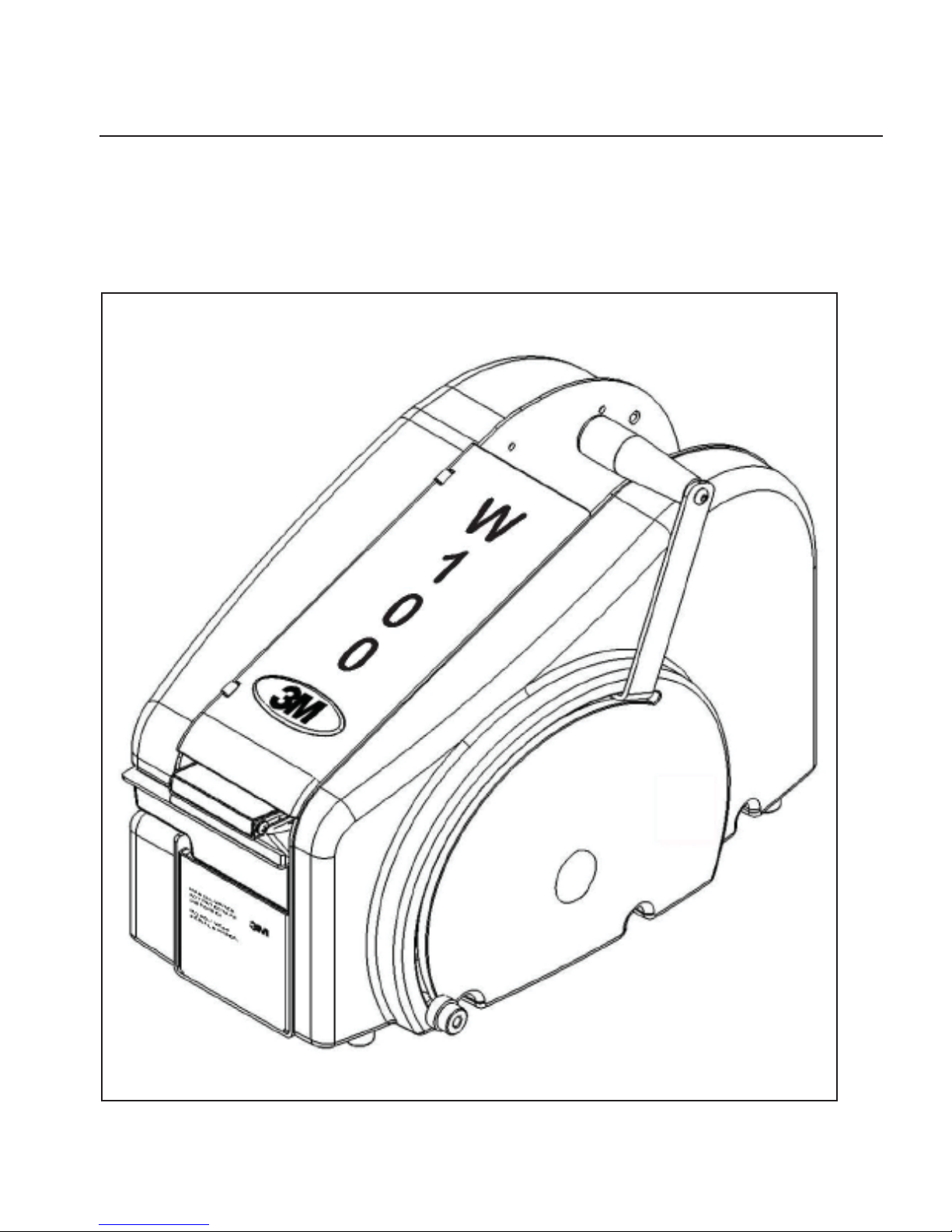
Congratulations on the purchase of your new water activated gummed tape dispenser (manual versiont). We are
confi dent you will be very pleased with the operation and performance of this durable, quality built dispenser for
many years to come.
The dispenser allows you to dispense gummed tape quietly, quickly, and accurately for a
variety of uses.
3MTM Water Activated Tape Dispenser (manual version), Type 11100
WaterAct-M-S
1
2011 October
Page 14

This Page is Blank
2
2
Page 15
2-GENERAL INFORMATION
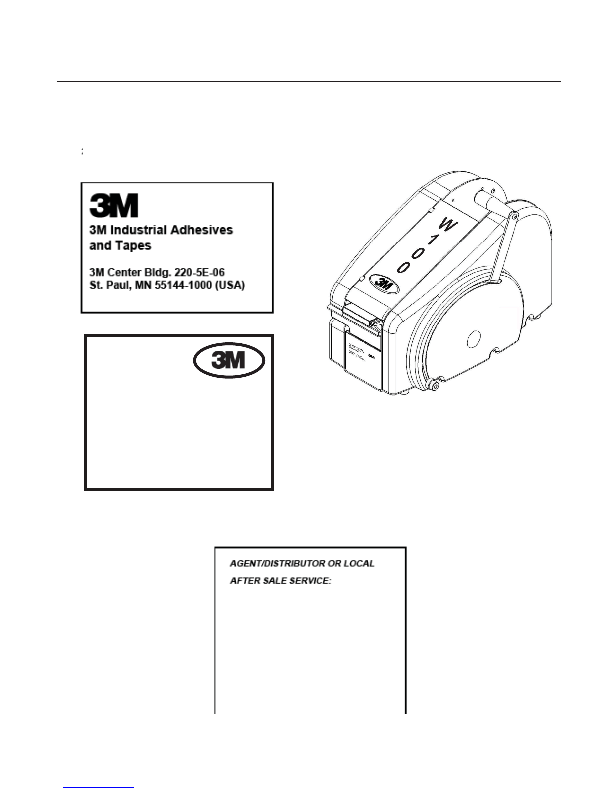
2.1 Data Identifying Manufacturer and Dispenser
MANUAL WATER
ACTIVATED TAPE
DISPENSER
MODEL: W100
SERIAL NUMBER:
2.2 Data for Technical Assistance and Service
For Commercial Use Only
WaterAct-M-S
3
2011 October
Page 16

2-GENERAL INFORMATION (continued)
Equipment Warranty and Limited Remedy: THE FOLLOWING WARRANTY IS MADE IN LIEU OF ALL OTHER
WARRANTIES, EXPRESS OR IMPLIED, INCLUDING, BUT NOT LIMITED T O, ANY IMPLIED WARRANTY OF
MERCHANTABILITY OR FITNESS FOR A PARTICULAR PURPOSE AND ANY IMPLIED WARRANTY ARISING
OUT OF A COURSE OF DEALING, CUSTOM OR USAGE OF TRADE:
2.2 Warranty
3M sells its 3M™ Water Activated Tape Dispenser, Type 11100 with the following warranties:
1. All 3M™ Water Activated Tape Dispenser parts will be free from defects for ninety (90)
days after delivery.
If any part is defective within this warranty period, your exclusive remedy and 3M’s and seller’s sole obligation shall
be, at 3M’s option, to repair or replace the part. 3M must receive actual notice of any alleged defect within a
reasonable time after it is discovered, but in no event shall 3M have any obligation under this warranty unless it
receives such notice within fi ve (5) business days after the expiration of the warranty period. All notices required
hereunder shall be given to 3M solely through the 3M™ Help line. To be entitled to repair or replacement as provided under this warranty, the part must be returned as directed by 3M to its factory or other authorized service station
designated by 3M. If 3M is unable to repair or replace the part within a reasonable time after receipt thereof, 3M, at
its option, will replace the equipment or refund the purchase price. 3M shall have no obligation to provide or pay for
the labor required to remove any part or equipment or to install the repaired or replacement part or equipment. 3M
shall have no obligation to repair or replace those parts failing due to normal wear, inadequate or improper maintenance, inadequate cleaning, non-lubrication, improper operating environment, improper utilities, operator error or
misuse, alteration or modifi cation, mishandling, lack of reasonable care, or due to any accidental cause.
Limitation of Liability: Except where prohibited by law, 3M and seller will not be liable for any loss or damage arising
from this 3M equipment, whether direct, indirect, special, incidental, or consequential, regardless of the legal theory
asserted, including breach of warranty, breach of contract, negligence, or strict liability.
Contents, Water Activated Tape Dispenser (manual version)
(1) Water Activated Tape Dispenser (manual version), Type 11100
(1) Operator's Manual
®
Scotch
, and 3MTM are Trademarks of 3M, St. Paul, Minnesota 55144-1000
WaterAct-M-S
4
2011 October
Page 17
1-SAFETY
3.1 How to Read and Use the Service Manual
This instruction manual covers safety aspects,
handling and transport, storage, unpacking, preparation, installation, operation, set-up and adjustments,
technical and manufacturing specifi cations, mainte-
nance, troubleshooting, repair work and servicing,
electric diagrams, warranty information, disposal, a
defi nition of symbols, plus a parts list of the 3M Wa-
ter Activated Tape Dispenser (manual version) 3M
Industrial Adhesives and Tapes Division 3M Center,
Bldg. 220-5E-06 St. Paul, MN 55144-1000 (USA) /
Edition October 2011 / Copyright 3M 2011 / All rights
reserved The manufacturer reserves the right to
change the product at any time without notice -
Publication © 3M 2011 44-0009-2107-0.
3.2.1 Importance of the Manual
The manual is an important part of the dispenser; all
information contained herein is intended to enable
the equipment to be maintained in perfect condition
and operated safely. Ensure that the manual is available to all operators of this equipment and is kept
up to date with all subsequent amendments. Should
the equipment be sold or disposed of, please ensure
that the manual is passed on. Electrical and pneumatic diagrams are included in the manual. Equipment using PLC controls and/or electronic components will include relevant schematics or programs in
the enclosure and in addition, the relevant documentation will be delivered separately.
3.2.2 Manual Maintenance
Keep the manual in a clean and dry place near the
dispenser. Do not remove, tear, or rewrite parts of
the manual for any reason. Use the manual without
damaging it. If the manual has been lost or damaged, ask your after sale service for a new copy.
3.2.3 Consulting the Manual
3.2.4 How to Update the Manual in Case of
Modifications to the Dispenser
Modifi cations to the dispenser are subject to manufac-
turer’s internal procedures. The user receives a complete and up-to-date copy of the manual together with
the dispenser. Afterwards the user may receive pages
or parts of the manual which contain amendments or
improvements made after its fi rst publication. The user
must use them to update this manual.
3.3 Table of Warnings
WARNING
• To reduce the risk associated with
mechanical hazards:
− Read, understand, and follow all safety and
operating instructions before operating or
servicing the tape dispenser.
− Allow only properly trained and qualifi ed
personnel to operate and service this
equipment.
CAUTION
• To reduce the risk associated with
sharp blade hazards:
− Keep hands and fi ngers away from
tape cutoff blades. The blades are
extremely sharp.
WARNING
Sharp Blade
The manual is composed of:
- Pages which identify the document and the
dispenser
- Index of the subjects
- Instructions and notes on the dispenser
- Enclosures, drawings and diagrams
- Spare parts (last section)
All pages and diagrams are numbered. The spare
parts lists are identifi ed by the fi gure identifi cation
number. All the notes on safety measures or
possible dangers are identifi ed by the symbol:
WaterAct-M-S
Figure 3-1
WARNING
• To reduce the risk associated with
muscle strain:
− Use proper body mechanics when
working on or moving the dispenser.
2011 October
5
Page 18

3-SAFETY (continued)
3.4 Operator's Qualifications
- Dispenser Operator
- Mechanical Technician
- Manufacturer’s Technician/Specialist
(See Section 3)
3.5 Number of Operators
The operations described below have been analyzed
by the manufacturer; the recommended number of
operators for each operation provides the best and
safest work performance.
WARNING
• To reduce the risk associated with
mechanical hazards:
− Read, understand, and follow all safety and
operating instructions before operating or
servicing the Tape Dispenser.
− Allow only properly trained and qualifi ed
personnel to operate and service this
equipment.
Note: A smaller or greater number of operators
could be unsafe.
3.6 Instructions for a Safe Use of the Dispenser /
Definition of Operator's Qualifications
Only persons who have the skills described in the
skill levels section should be allowed to work on the
dispenser. It is the responsibility of the user to appoint the operators having the appropriate skill level
and the appropriate training for each category of job
(See Section 3).
3.7 Residual Hazards
The Water Activated Tape Dispenser (manual version) incorporates various safety protections which
should never be removed or disabled (notwithstanding the safety precautions conceived by the designers of the dispenser).
3.8 Personal Safety Measures
Safety glasses, safety gloves, safety helmet, safety
shoes, air fi lters, ear muffs - None is required except
when recommended by the user.
3.9 Predictable Actions which are Incorrect and
Not Allowed
- Never work without the safety protections.
- Only authorised personnel should be allowed to
carry out the adjustments, repairs or maintenance
which require operation with reduced safety
protections. During such operations, access to the
dispenser must be restricted. When the work is
fi nished, the safety protections must immediately be
reactivated.
- Do not modify the dispenser or any part of it. The
manufacturer will not be responsible for any
modifi cations.
Follow carefully the installation instructions of this
manual.
WaterAct-M-S
6
2011 October
Page 19

3-SAFETY (continued)
WARNING
• To reduce the risk associated with
mechanical hazards:
− Allow only properly trained and qualifi ed
personnel to operate or service this
equipment
Skill 2: Mechanical Maintenance Technician
This operator is trained to use the dispenser as the
Dispenser OPERATOR and in addition is able to work
with the safety protection disconnected, to check and
adjust mechanical parts, to carry out maintenance operations and repair the dispenser.
3.10 Operator Skill Level Descriptions
Skill 1: Dispenser Operator
This operator is trained to use the dispenser through
any controls, to load and un-load the Dispenser
Tape.
Important: The factory manager should ensure that
the operator has been properly trained on all the
functions of the dispenser before starting work.
Required Operator Skill Levels
Operation
Installation and set up of the
dispenser. N/A for this dispenser (idle)
Replacement of the Dispenser
Tape.
N/A for this dispenser (idle) 1 1
Skill 3: Specialist From the Manufacturer
Skilled operator sent by the manufacturer or its
agent to perform complex repairs or modifi cations,
when agreed with the customer.
State of the
Dispenser
Opera-
tor's
Skill
1 or 2 1
Number
of Op-
erators
Loading, wrapping and
unloading.
Ordinary maintenance. N/A for this dispenser (idle) 2 1
Extraordinary maintenance
(mechanical).
Extraordinary maintenance N/A for this dispenser (idle) 3 1
Extraordinary maintenance
(electrical).
WaterAct-M-S
N/A for this dispenser (idle) 1 1
N/A for this dispenser (idle) 2 1
41
Running with safety protections
disabled.
3a or 4 1
2011 October
7
Page 20

3-SAFETY (continued)
3.11 Component Locations
Refer to Figure 3-2 below to acquaint yourself with the various components and controls of the Tape Dispenser.
Tape Mount
Applicator
Handle
Top
Cover
Water
Tank
Brush
Assembly
Figure 3-2—Water Activated Tape Dispenser Components (manual version)
WaterAct-M-S
8
2011 October
Page 21
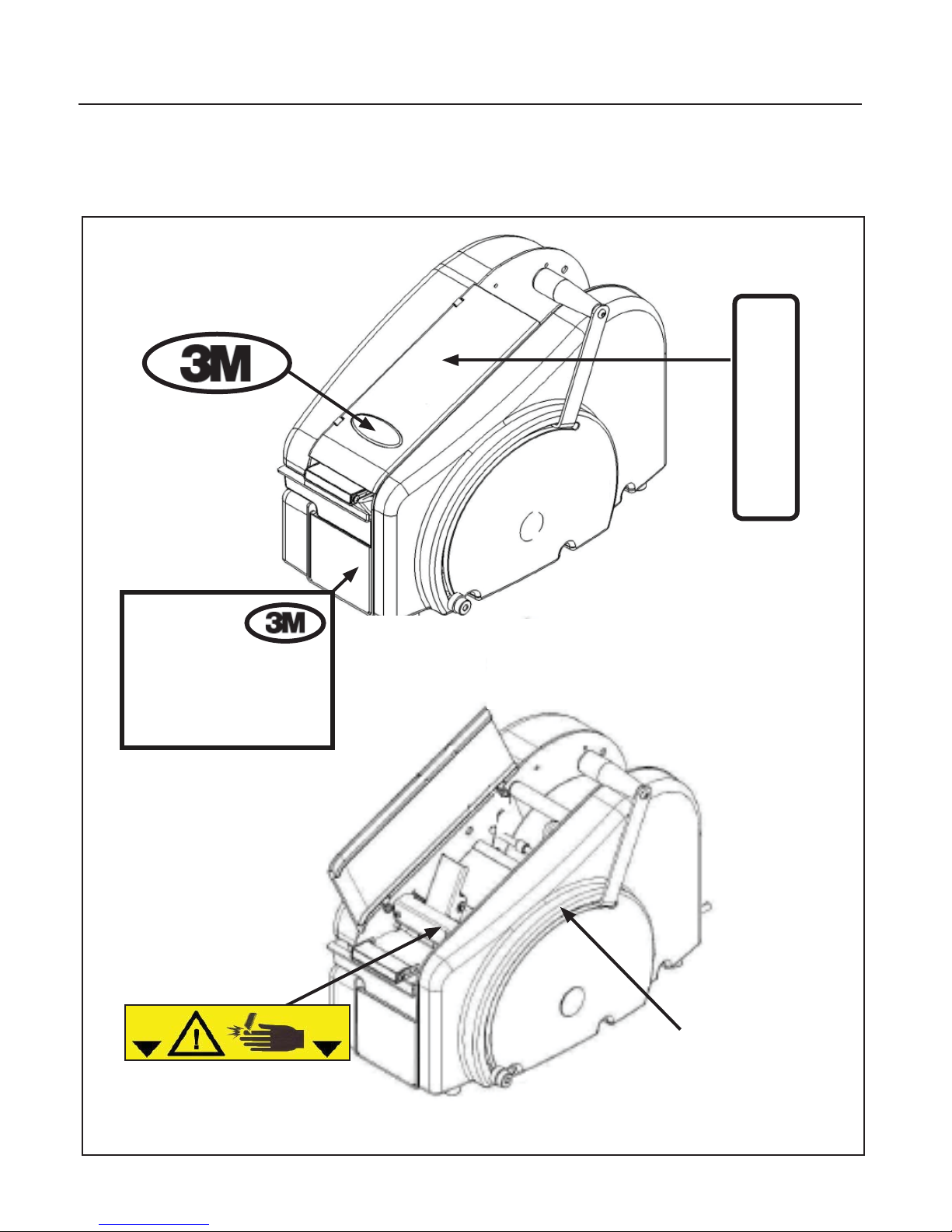
3-SAFETY (continued)
3.12 Safety Warning Labels
If the following safety labels are damaged or destroyed, they must be replaced to ensure operator safety.
Replacement part numbers for individual labels are shown in Figure 3-3.
W
1
78-8137-5487-2
0
0
78-8137-5488-0
MANUAL WATER
ACTIVATED TAPE
DISPENSER
MODEL: W100
SERIAL NUMBER:
78-8137-5483-1
78-8137-5494-8
Label Tape Length
78-8137-5490-6
Figure 3-3—Replacement Labels and 3MTM Part Numbers
WaterAct-M-S
9
2011 October
Page 22

4-SPECIFICATIONS
10.5 in
26.6 cm
13.7 in
34.8 cm
18.9 in
Figure 4-1
48.0 cm
1. Shipping Weight:
Unboxed: 25 pounds (11.3 kg)
Boxed: 31 pounds (14.1 kg)
2. Tape:
Dry gummed tape – paper or reinforced – between 1 to 3 inches (25.4 to 76.2 mm) wide, up to 1000 feet
(304.8 m) long and 9 inches (228.6 mm) max roll diameter
3. Dispenser Dimensions:
(See Figure 4-1)
4. Operating Conditions:
Use in dry, relatively clean environments at 5 oC / 40 oC [40 oF / 105 oF].
Note: Dispenser should not be washed down or subjected to conditions causing moisture condensation on
component
WaterAct-M-S
10
(Specifi cations continued on next page.)
2011 October
Page 23

5-SHIPMENT-HANDLING-STORAGE, TRANSPORT
5.1 Shipment and Handling of Packed Dispenser
The packaging is suitable for travel by land, air and
sea freight.
See Specifi cations.
5.2 Handling and Transportation of Uncrated
Dispenser
Use proper body mechanics when moving the dispenser
(Figure 5-1).
5.3 Storage of the Packed or Unpacked Dispenser
If the dispenser is not used for a long period,
please take the following precautions:
- Store the dispenser in a dry and clean place.
(Never move the dispenser without packaging)
- If the dispenser is unpacked it is necessary to
protect it from dust.
- Do not stack anything over the dispenser.
Figure 5-1
WaterAct-M-S
11
2011 October
Page 24

6-INSTALLATION
6.1 Operating Conditions
See Specifi cations.
6.2 Space Requirements for Dispenser Operation
and Maintenance Work
N/A for this dispenser.
Generally, for ease of operation, allow spacing around
dispenser as needed.
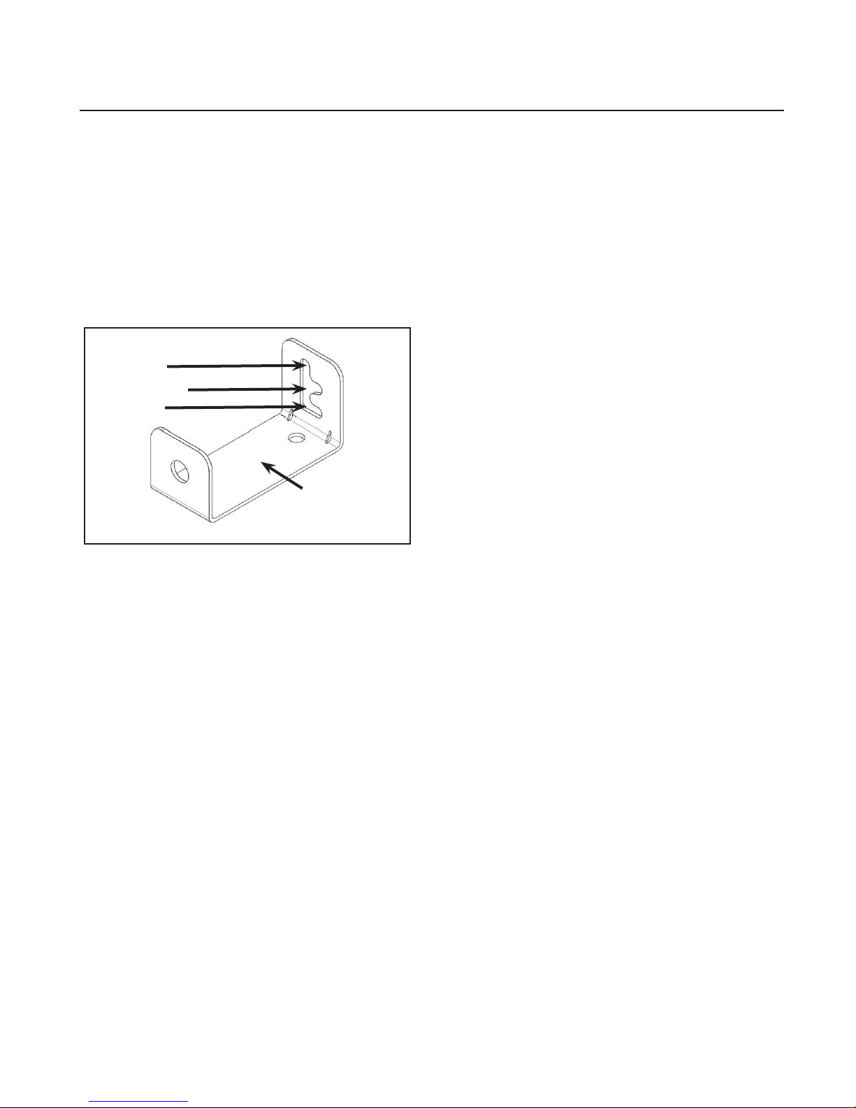
6.3 Tools needed for Repairs (Figure 6-1)
Important! Before attempting repairs, loosen foot
channels (Figure 6-2). Loosening foot
channels allow the chassis to "relax" while
facilitating ease of repairs. Failure to
loosen foot channels may result in diffi culties
with repairs and reassembling dispenser.
WARNING
• To reduce the risk associated with
muscle strain:
− Use appropriate body mechanics when
lifting or repositioning this equipment.
Note: When attempting repairs to sheet metal,
do not overtighten screws.
Below is a list of the tools that are recommended for
disassembly and assembly of dispenser.
Needle nose pliers
Vice grips
3/8” fl at head screw driver
#2 4” Phillips head screw driver
#2 8” Phillips head screw driver
5/16" wrench or socket
3/8” wrench or socket
7/16” wrench or socket
1/2” wrench or socket
15/16" socket
3/32” long hex key
5/64” hex key
1/8” hex key
3/16” hex key
1/4” hex key
Loosen both
Screws on
Bottom of
Chassis
WaterAct-M-S
Figure 6-2
Figure 6-1
6.4 Dispenser Positioning
N/A for this dispenser.
Use proper mechanics in lifting and positioning
dispenser. Place in an elevated and a comfortable
operating position.
WARNING
• To reduce the risk associated with
a mechanical hazard:
− Read, understand, and follow all safety and
operating instructions before operating or
servicing the Tape Dispenser.
12
2011 October
Page 25

6-INSTALLATION (continued)
6.5
Leveling
Set the platform on a fl at surface which allows for even
weight distribution (Figure 6-4).
6.6 Loading Tape (Figures 6-5 and 6-6)
1. Open top cover of dispenser.
2. Using tape guide turnbuckle, adjust width of tape guides
to accommodate the tape.
3. Place tape roll in dispenser.
4. Using tape guide turnbuckle, re-adjust tape guides
leaving an 1/8” clearance on both sides of the tape.
5. Remove pressure plate from dispenser.
6. Feed tape (gummed side down) over top roller, under
tape guide fl aps, and under pinch roller (Figure 6-5).
Note: For Tape that is "gummed side out" (typically used
in Europe), load tape roll opposite as shown while
routing with gummed side (over the top roller).
7. Place pressure plate over tape and release pinch roller.
The pressure plate must be loaded so it touches the
pinch roller shaft and the arrow on the pressure plate
points toward front of dispenser.
8. Close top cover.
WARNING
• To reduce the risk associated with
muscle strain:
− Use appropriate body mechanics when
lifting or repositioning this equipment.
Figure 6-4
Pressure Plate
Top Cover
Tape Guide
Pinch Roller
Top
Roller
Tape Guide
Turnbuckle
Length Scale
WaterAct-M-S
Mechanical Stop
13
Figure 6-5
2011 October
Page 26

6 - INSTALLATION (continued)
Pinch Roller
Shaft
Cutter
Assembly
Pinch
Roller
Pressure
Plate
Top Roller
Tape
(standard threading)
Tape Roll
(1000 ft.)
Tape
(gummed side
facing out)
Water
Bottle
Brackets
Post
Figure 6-6
Water Bottle
Duck Bill Valve
Tape Weight
Brush Tank
WaterAct-M-S
14
Figure 6-7
2011 October
Page 27
6-INSTALLATION (continued)
6.7 Water Bottle Filling (Figures 6-7 and 6-8).
1. Remove water bottle from dispenser.
2. Remove duckbill valve from water bottle.
3. Fill water bottle with clean or distilled water
(Figure 6-7).
4. Place duckbill valve back into water bottle.
5. Place water bottle back on the dispenser.
Check to be sure the post in the brush tank is
inserted through the duckbill valve
(Figure 6-7).
Low
Medium
High
Water Bottle
Bracket
Figure 6-8
6-8 Brush Tank Water Level Adjusting
(Figures 6-7 and 6-8).
1. Loosen the retaining screws on the water bottle
brackets.
2. Move the water bottle brackets to the desired
position to obtain the desired water level in the
brush tank (Both brackets should be at the
same position).
Note: Lightweight tapes would typically be set
at the low position (Figure 6-8).
3. Tighten the retaining screws on the water bottle
brackets.
6-9 Tape Weight Adjusting
(Figure 6-7)
1. Loosen retaining screw.
2. Slide tape weight forward for greater
pressure (this applies more water to tape
and is typically used on heavy weight tapes).
3. Slide tape weight back for less pressure.
(this applies less water to tape and is
typically used on lighter weight tapes).
4. Tighten retaining screw.
WaterAct-M-S
15
2011 October
Page 28

7-OPERATION
7.1 Operating Instructions
Once the dispenser has been properly set up for use, pull the operating handle to the desired length
(indicated on handle scale). Releasing the handle automatically cuts the tape.
Note: The dispenser can be set to accommodate work where a known length will be used.
The dispenser can be set to accommodate work where a known length will be used. A mechanical stop is provided on the side of the dispenser. The mechanical stop can be moved to any desired position by loosening the
knurled nut a half of a turn and sliding the nut up or down within the slot. When placed in the desired position,
re-tighten the knurled nut to set the desired length of tape to be dispensed.
Important: Do NOT remove the knurled nut.
WARNING
• To reduce the risk associated with a mechanical hazard:
− Read, understand, and follow all safety and operating instructions before operating or servicing the
tape dispenser.
WaterAct-M-S
16
2011 October
Page 29
8-MAINTENANCE AND REPAIRS
8.1 Safety Measures (see section 3)
The manually operated Tape Dispenser requires very
little maintenance. It is important to regularly clean the
brush tank and cutter mechanism. Be sure to also
remove any debris from the tape path.
Important! Before attempting repairs, loosen the foot
channels (See Section 6). Loosening foot
channels allow the chassis to "relax" while
facilitating ease of repairs. Failure to
loosen foot channels may result in diffi culties
making repairs and reassembling the dispenser.
8.4 Inspections to be Performed Before and
After Every Maintenance Operation
During the maintenance operation only the operator
responsible for this duty must work on the dispenser.
At the end of every maintenance operation check the
dispenser functions (See Section 8.3).
WARNING
• To reduce the risk associated with
a mechanical hazard:
− Read, understand, and follow all safety and
operating instructions before operating or
servicing the Tape Dispenser.
− Allow only properly trained and qualifi ed
personnel to operate and service this
equipment.
8.2 Supplied with the Dispenser
- Instruction and Spare Parts Manual
8.3 Recommended Frequency of Inspection and Maintenance Operations
Operation Frequency Qualif cation
Inspection safety features Daily 2
Clean the brush, Daily 1
Clean the brush tank Monthly 1
Clean the cutter mechanism As needed 1
Remove debris from the tape path As needed 1
8.5 Check Eff ciency of Safety Features
N/A
WaterAct-M-S
17
2011 October
Page 30

8-MAINTENANCE AND REPAIRS (continued)
8.6 Cleaning the Water Feed System:
1. Clean the brush by soaking it in warm soapy
water. Rinse thoroughly.
2. Clean brush tank, duckbill valve, and water bottle
with warm water.
Tape
Water
Tank
Holder
Cutter
Guard
Cleaning
Pressure
Plate
Channel
Gaps
Weight Tank
Brush Cover
8.7 Cleaning the Cutter Assembly (Figure 8-2)
1. Open top cover.
2. Remove pressure plate.
3. Remove the tape from the tape path.
4. Spray available gaps in front and behind the
cutter guard (use minimal amount of a
non-fl ammable super penetrating lubricant -
WD 40 or Industrial Silicon Spray are
recommended). Wipe off any excess.
Top
Cover
Cutter
Assembly
8.8 Cleaning the Tape Path (Figure 8-1)
1. Press power switch to OFF (I) position and unplug power cord.
2. Open top cover.
3. Remove pressure plate.
4. Remove tape from tape path.
5. Remove cutter guard.
6. To remove debris and adhesive build-up in tape path, use a moist cloth to wipe down all sheet metal
parts (tape channel, pressure plate, weighted brush tank cover, and water tank holder).
7. Using compressed air remove all debris and any visible moisture from tape path.
8. Replace cutter guard.
9. Place tape back into tape path (Refer to Tape Loading - Section 9).
10. Place pressure plate back in dispenser.
11. Close top cover.
WaterAct-M-S
18
Figure 8-1
2011 October
Page 31

8-MAINTENANCE AND REPAIRS (continued)
CAUTION
• To reduce the risk associated with
pinch hazards:
− Keep hands, hair, loose clothing, and
jewelry away from dispenser.
8.9 Handle
To Remove:
1. Remove handle hole plug (Figure 8-2).
2. Remove 15/16 inch nut.
3. Slide handle OFF handle shaft.
4. Rotate handle forward to about 12 inch
mark on right side cover and pull
handle gently from dispenser (Figure 8-3).
New Part Installation:
Reverse the removal procedure above.
Figure 8-2
Remove
Nut and
Slide handle
off shaft
Rotate Handle
to 12 inch
mark and
remove
Figure 8-3
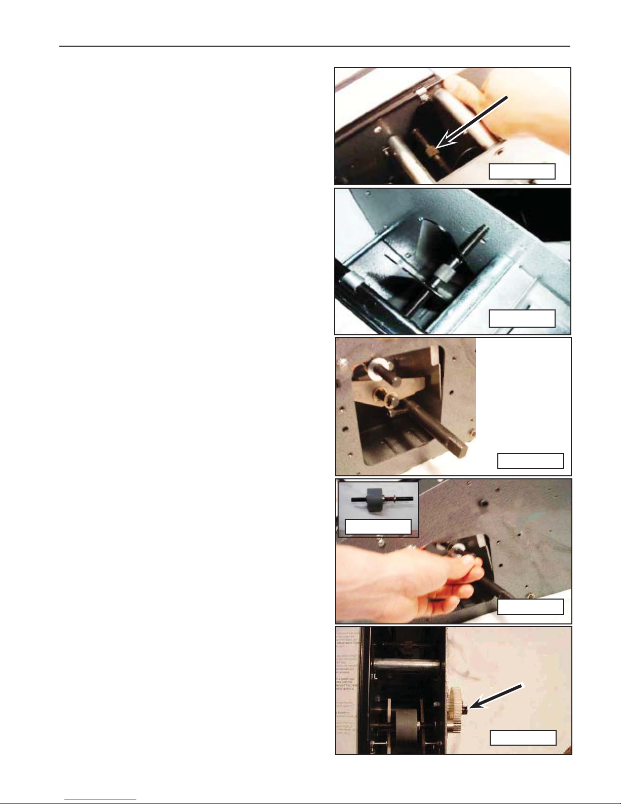
8.10 Handle Shaft
To Remove:
1. Remove right side cover (See Section 8.11).
2. Remove left side cover (See Section 8.12).
3. Remove pinch roller (See Section 8.19).
4. Remove weighted brush cover
(See Section 8.23).
5. Remove tape channel plate
(See Section 8.25).
6. Remove idler gear (See Section 8.29).
7. Remove drive gear and clutch assembly
(See Section 8.30).
8. Remove cutter arm springs from screws
they are resting upon (Section 8.15).
9. Remove gearbox/motor mount
(Section 8.32).
10. Remove large e-clip from left side of
the handle shaft (Figure 8-4).
11. Remove handle shaft from the chassis and
(if needed) insert a new handle shaft into 1/2"
bearing (Figure 8-5).
Figure 8-4
E-Clip
Figure 8-5
Handle
Shaft
New Part Installation:
Reverse the removal procedure above.
WaterAct-M-S
19
2011 October
Page 32

8-MAINTENANCE AND REPAIRS (continued)
8.11 Right Side Cover
To Remove:
1. Remove the water bottle and duckbill valve.
2. Remove the water tank and brush.
3. Open the top cover (Figure 8-6).
4. Remove the handle hole plug.
5. Remove 15/16 inch nut from the handle shaft.
6. Remove three screws on inside of dispenser
(Figure 8-6).
7. Remove three screws on outside of dispenser
(Figure 8-7).
8. Slide handle to the end of handle shaft.
Slowly remove right side cover / handle.
(Figure 8-8).
9. At this point a new right side cover may
be installed.
New Part Installation:
Reverse the removal procedure above.
8.12 Left Side Cover
To Remove:
1. Remove water bottle and duckbill valve.
2. Remove water tank and brush.
3. Remove three (3) screws along bottom
edge of left side cover (Figure 8-9).
4. Slide left side cover towards bottom of
dispenser, and remove left side cover
(Figure 8-10).
New Part Installation:
Figure 8-6
Figure 8-7
Figure 8-8
Figure 8-9
Remove 3
Screws on
Inside of
Dispenser
Remove 3 Screws on
Outside of Dispenser
Remove-
Screws
Reverse the removal procedure above.
8.13 Front Cover
To Remove:
1. Remove right side cover (See Section 8.11).
2. Remove left side cover (See Section 8.12).
3. Loosen screws of the following parts: coder
bar and dead roller, brush tank holder, and
weighted brush cover shaft (See Section 8.23).
4. Remove four (4) screws from front cover.
5. Remove front cover (Figure 8-11).
6. With one hand pushing chassis slightly apart,
position new front cover.
New Part Installation:
7. Attach the screws to the front cover.
8. Tighten loosened screws (see #3).
Figure 8-10
Figure 8-11
E-Clip
Slide
Down
WaterAct-M-S
20
2011 October
Page 33

8-MAINTENANCE AND REPAIRS (continued)
8.14 Water Tank Holder
To Remove:
1. Remove right side cover (See Section 8.11).
2. Remove left side cover (See Section 8.12).
3. Loosen screws in coder bar and dead
roller (Figure 8-12).
4. Remove our (4) screws from front cover.
5. Remove front cover (Figure 8-13).
6. Remove seven (7) screws from water
tank holder.
7. Remove water tank holder (Figure 8-14).
New Part Installation:
Reverse the removal procedure above.
WARNING
• To reduce the risk associated with
mechanical hazards:
− Read, understand, and follow all safety and
operating instructions before operating or
servicing the tape dispenser.
− Allow only properly trained and qualifi ed
personnel to operate and service this
equipment.
Figure 8-12
Figure 8-13
Figure 8-14
Figure 8-15
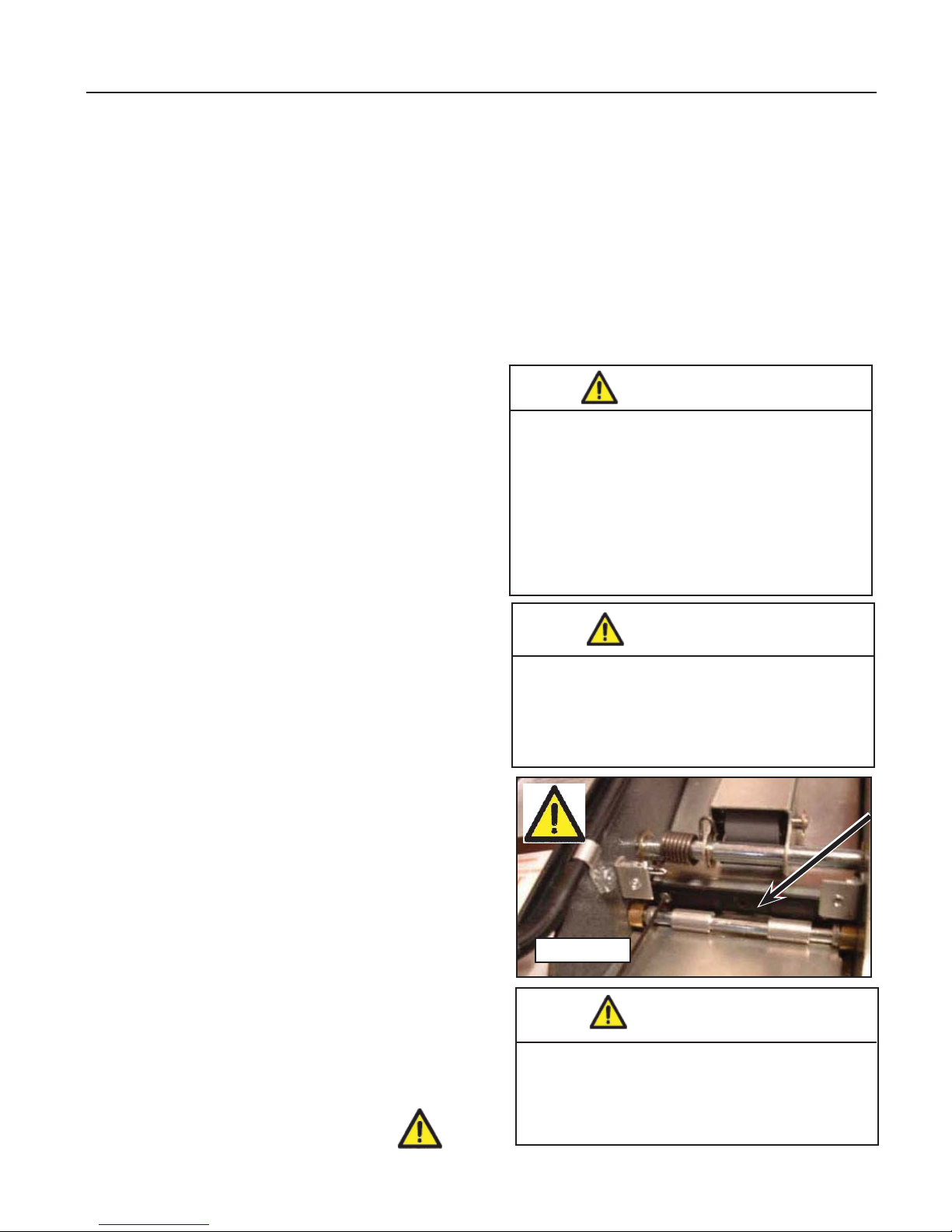
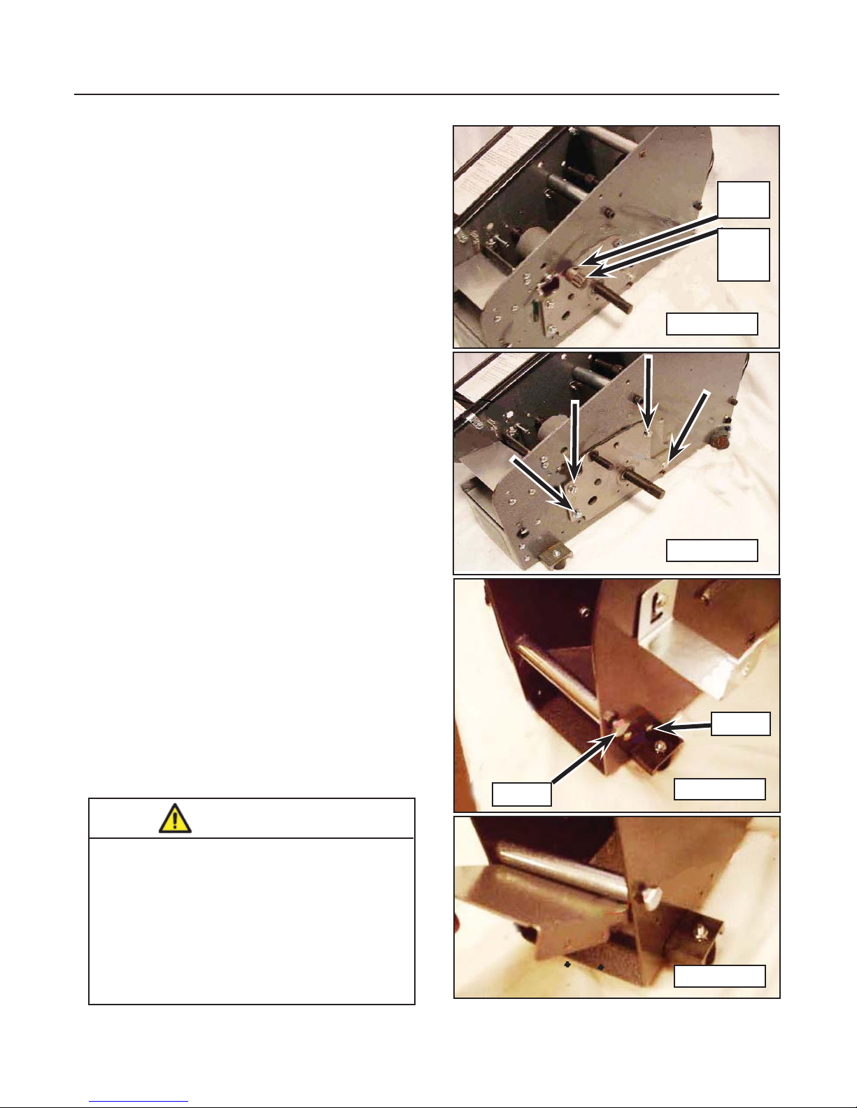
8.15 Cutter Return Spring
To Remove:
1. Remove right side cover (See Section 8.11).
2. Remove left side cover (See Section 8.12).
3. Remove screws from the front cover and
remove.
4. Attach a pair of vice grips to the cutter return
spring screw (Figure 8-15).
5. While holding the vice grips, remove nut on
inside of dispenser (Figure 8-16).
6. Slowly pull screw from the chassis and
release tension from cutter return
spring (Figure 8-17).
7. Remove cutter slide bolt from the handle
shaft (Figure 8-18).
New Part Installation:
Reverse the removal procedure above.
Figure 8-16
Figure 8-17
Cutter
Slide
Bolt
Figure 8-18
WaterAct-M-S
21
2011 October
Page 34

8-MAINTENANCE AND REPAIRS (continued)
8.16 Movable Cutter Blade
To Remove:
1. Remove Cutter Guard.
2. Remove right side cover (See Section 8.11).
3. Remove cutter guard clips.
4. Loosen set screw to release tension from blade
(Figures 8-19).
5. With one hand pushing down on the handle
(Figures 8-20), remove two (2) remaining
screws and lift moveable cutter blade out of
dispenser.
Important: Place a pencil or screw driver under the
blade so that the it doesn't fall into the dispenser.
6. With one hand holding new moveable cutter
blade, place new blade so two (2) outside screw
holes line up. Screw blade into place.
7. Tighten set screw so that there is a slight bend
in the movable cutter blade.
New Part Installation:
Reverse the removal procedure above.
Figure 8-19
CAUTION
• To reduce the risk associated with
sharp blade hazards:
− Keep hands and fi ngers away from
tape cutoff blades. The blades are
extremely sharp.
8.17 Fixed Blade
To Remove:
1. Loosen screw retaining the fi xed blade stop
and remove stop.
2. Remove fi xed blade retaining screw.
3. Push fi xed blade shoe toward rear of dispenser
(Figures 8-21).
4. Use a magnet, pull fi xed blade from dispenser.
(Figures 8-22).
5. Insert new fi xed blade into chassis.
Important: The blade should be resting on both
sides of the chassis.
Caution: Do not drop any components into the
dispenser.
Figure 8-20
Figure 8-21
7. Release the fi xed blade shoe.
8. Reinstall the fi xed blade retaining screw.
9. Reinstall fi xed blade stop and tighten
retaining screw.
WaterAct-M-S
22
Figure 8-22
2011 October
Page 35

8-MAINTENANCE AND REPAIRS (continued)
8.18 Cutter Arms
To Remove:
1. Remove right side cover (See Section 8.11).
2. Remove left side cover (See Section 8.12).
3. Remove pinch roller (See Section 8.19).
4. Remove weighted brush cover
(See Section 8.23).
5. Remove tape channel plate
(See Section 8.25).
6. Remove water tank holder
(See Section 8.14).
7. Remove cutter arm springs from the screws
they rest on (Figure 8-23).
8. Remove e-clips from cutter arm shaft
(Figure 8-24).
9. Remove cutter arm shaft from chassis
(Figure 8-25).
10. Remove cutter arms.
New Part Installation:
Install new part and reverse the removal
procedure above.
8.19 Pinch Roller
Cutter
Arm Springs
Figure 8-23
Figure 8-24 Figure 8-25
To Remove:
1. Remove water bottle.
2. Remove pressure plate (Figure 8-26).
3. Facing front of dispenser, pull pinch roller spring
tofront and to left of dispenser until spring is no
longer on the pinch roller (Figure 8-27).
4. Release pinch roller spring gently.
5. Remove four (4) 3/8” e-clips from
pinch roller shaft.
Important: Do not let the e-clips fall into dispenser.
6. With one hand holding pinch roller and
pinch roller spring, slide pinch roller shaft to
the left until the pinch roller shaft is no longer
on the chassis (Figure 8-28).
New Part Installation:
1. With left end of the pinch roller spring on
top of the screw and on left side of dispenser,
slide pinch roller shaft into right side of
chassis (Figure 8-29).
Complete the Installation by reversing the
removal procedure above.
Figure 8-26
Figure 8-27
Note: Insert shaft approximately ¼ way in chassis.
WaterAct-M-S
23
Figure 8-28
Figure 8-29
2011 October
Page 36

8-MAINTENANCE AND REPAIRS (continued)
8.20 Top Roller
To Remove:
1. Remove right side cover (See Section 8.11).
2. Remove e-clips from top roller shaft.
3. Remove top roller shaft.
4. Remove top roller tube.
5. Place new top roller into middle of chassis and
hold.
6. Insert new top roller shaft through -
- chassis -
- top roller
- and chassis on other side
(Figure 8-30)
New Part Installation:
Reverse the removal procedure above.
8.21 Free Spin Roller Shaft
To Remove:
1. Remove right side cover (See Section 8.11).
2. Remove left side cover (See Section 8.12).
3. Remove e-clips from free spin roller shaft
(Figure 8-31).
4. Remove free spin roller shaft.
5. Remove free spin roller tube.
New Part Installation:
E-Clip
Top
Roller
Top
Roller
Shaft
E-Clips
Figure 8-30
Figure 8-31
Reverse the removal procedure above.
8.22 Slide Roller
To Remove:
1. Remove right side cover (See Section 8.11).
2. Remove (4) screws holding the sliding
roller plates (Figure 8-32).
3. Remove slide roller assembly (Figure 8-33).
New Part Installation:
Reverse the removal procedure above.
WARNING
• To reduce the risk associated with
mechanical hazards:
− Read, understand, and follow all safety and
operating instructions before operating or
servicing the tape dispenser.
− Allow only properly trained and qualifi ed
personnel to operate and service this
equipment.
Screws
Figure 8-32
Figure 8-33
WaterAct-M-S
24
2011 October
Page 37

8-MAINTENANCE AND REPAIRS (continued)
8.23 Weighted Brush Cover
To Remove:
1. Remove the right side cover
(See Section 8.11).
2. Remove the water bottle.
3. Remove the cutter guard.
4. Remove the screws from the fl apper shaft
(Figure 8-34).
5. Slide the fl apper shaft, weighted brush cover,
tape weight, and bushings from the front
of the dispenser (Figure 8-35).
6. Remove the screw from the tape weight and
remove the tape weight from the weighted
brush cover.
New Part Installation:
Reverse the removal procedure above.
Remove
Screw
Figure 8-34
8.24 Brush
To Remove:
1. Remove Water Bottle.
2. Remove Water Tank.
3. Remove Brush from Water Tank.
4. Place new brush in the tank with bristles
level with work area/fl oor (Figure 8-36).
5. Place tank and brush in water tank holder.
6. Place the water bottle on bottle brackets with
post of water tank inserted into duckbill valve.
New Part Installation:
Reverse the removal procedure above.
CAUTION
• To reduce the risk associated with
pinch hazards:
− Keep hands, hair, loose clothing, and
jewelry away from dispenser.
Figure 8-35
Brush Parallel
WrongRight
Figure 8-36
WaterAct-M-S
25
2011 October
Page 38

8-MAINTENANCE AND REPAIRS (continued)
8.25 Tape Channel Plate
To Remove:
1. Remove right side cover (See Section 8-11).
2. Remove pinch roller (See Section 8-19).
3. Remove weighted brush cover
(See Section 8-23).
4. Loosen dead roller and coder bar screws
(Figure 8-38).
5. Remove pinch roller spring stop (Figure 8-38).
6. Remove two (2) screws attached to tape
channel plate.
7. Pull tape channel plate up allowing tape
channel plate and dead roller to rotate (making
screws underneath accessible - Figure 8-39).
8. Remove two (2) screws connecting tape channel
plate and dead roller (Figure 8-40).
New Part Installation:
1. With the left end of pinch roller spring on
top of screw and left side of the dispenser,
slide the pinch roller shaft into right side of
chassis.
Figure 11-19
Figure 8-37
Tape Channel
Plate
5
5
6
Reverse the removal procedure above.
Note: Insert shaft approximately 1/4 way in chassis.
8.26 Tape Basket / Motor Cover
To Remove:
1. Remove right side cover (See Section 8-11).
2. Remove left side cover (See Section 8-12).
3. Remove pinch roller (See Section 8-19).
4. Remove weighted brush cover
(See Section 8-23).
5. Remove tape channel plate
(See Section 8-25).
6. Remove two (2) screws holding tape basket/
motor cover.
7. Remove tape basket/motor cover by lifting
straight up parallel with angle of tape basket/
motor cover (Figure 8-41).
8. Remove-inspect-and/or install new tape basket
(Figure 8-42).
Figure 8-38 Figure 8-39
Figure 8-40
Figure 8-41
New Part Installation:
Reverse the removal procedure above.
WaterAct-M-S
26
2011 October
Page 39
8-MAINTENANCE AND REPAIRS (continued)
8.27 Tape Guide Assembly
To Remove:
1. Remove right side cover (See Section 8.11).
2. Remove left side cover (See Section 8.12).
3. Remove pressure plate.
4. Loosen screws of these parts: coder bar and
dead roller, the tape basket/motor cover (See
Section 8.16), tape channel plate (See Section
8.25), and weighted brush cover shaft
(See Section 8.23).
5. With tape guides positioned towards middle of
dispenser and one hand spreading chassis
apart, pull turnbuckle to one side of dispenser,
twist turnbuckle slightly and pull assembly out
rear of dispenser (Figures 8-42 and 8-43).
6. With new tape guides set towards middle
of dispenser and slightly twisted, spread the
chassis apart and put both ends of the
turnbuckle into the chassis.
New Part: Reverse the removal procedure above.
Figure 8-42
Figure 8-43
8.28 Feed Wheel
To Remove:
1. Remove right side cover (See Section 8.11).
2. Remove the pinch roller (See Section 8.19).
3. Remove weighted brush cover
(See Section 8.23).
4. Remove tape channel plate
(See Section 8.25).
5. Remove idler gear (See Section 8.29).
6. Remove drive gear and clutch assembly
(See Section 8.30).
7. Remove gearbox/motor mount (Section 8.32).
8. Remove feed wheel shaft and feed wheel from
chassis at a downward angle (Figure 8-44).
9. Attach e-clip and washer to new feed wheel
shaft and insert back into dispenser
(Figures 8-45 and 8-46).
New Part: Reverse the removal procedure above.
8.29 Idler Gear
To Remove:
1. Remove right side cover (See Section 8.11).
2. Remove left side cover (See Section 8.12).
3. Remove weighted brush cover
(See Section 8.23).
4. Remove tape channel plate
(See Section 8.25).
5. Remove bolt from the center of idler gear
(Figure 8-47).
Figure 8-44
Figure 8-45
Figure 8-46
New Part: Reverse the removal procedure above.
WaterAct-M-S
27
Figure 8-47
2011 October
Page 40

8-MAINTENANCE AND REPAIRS (continued)
8.30 Drive Gear with Springs
and Clutch Assembly
To Remove:
1. Remove right side cover (See Section 8.11).
2. Remove pinch roller (See Section 8.19).
3. Remove weighted brush cover
(See Section 8.23).
4. Remove tape channel plate
(See Section 8.25).
5. Remove idler gear (See Section 8.29).
6. Remove drive gear and clutch assembly
(Figure 8-48).
New Part Installation:
Reverse the removal procedure.
Figure 8-48
8.31 Separating/Re-Assembling Drive Gear with
Springs and Clutch Assembly
To Separate:
1. Remove drive gear springs from the clutch
pins (Figure 8-49).
2. Pull drive gear with springs and clutch
assembly apart (Figure 8-50).
To Re-Assemble:
Reverse the separation procedure above.
WARNING
• To reduce the risk associated with
mechanical hazards:
− Read, understand, and follow all safety and
operating instructions before operating or
servicing the tape dispenser.
− Allow only properly trained and qualifi ed
personnel to operate and service this
equipment.
Figure 8-49
WaterAct-M-S
28
Figure 8-50
2011 October
Page 41
8-MAINTENANCE AND REPAIRS (continued)
8.32 Gear Box / Motor Mount
To Remove:
1. Remove right side cover (See Section 8.11).
2. Remove pinch roller (See Section 8.19).
3. Remove weighted brush cover
(See Section 8.23).
4. Remove tape channel plate
(See Section 8.25).
5. Remove idler gear (See Section 8.29).
6. Remove drive gear and clutch assembly
(See Section 8.30).
7. Remove set screw from feed wheel gear
(Figure 8-51).
8. Remove feed wheel gear (Figure 8-51).
9. Remove bolts from gearbox/motor mount.
(Figure 8-52).
10. Remove gearbox/motor mount.
New Part Installation:
Reverse the removal procedure above.
Set
Screw
Feed
Wheel
Gear
Figure 8-51
8.33 Ramp
To Remove:
1. Remove right side cover (See Section 8.11).
2. Remove left side cover (See Section 8.12).
3. Loosen screws on these parts: coder bar and
dead roller - weighted brush cover shaft.
4. Remove four (4) screws holding ramp.
Remove the ramp (Figure 8-53).
5. Attach four (4) screws to new ramp inside
locate thicker end of the ramp toward rear of
dispenser (Figure 8-54).
6. Tighten loosened screws in #4 and reattach left
and right covers.
New Part Installation:
Reverse the removal procedure above.
WARNING
• To reduce the risk associated with
mechanical hazards:
− Read, understand, and follow all safety and
operating instructions before operating or
servicing the tape dispenser.
− Allow only properly trained and qualifi ed
personnel to operate and service this
equipment.
Screw
Figure 8-52
Screws
Figure 8-53
Figure 8-54
WaterAct-M-S
29
2011 October
Page 42

8-MAINTENANCE AND REPAIRS (continued)
8.34 List of the Maintenance Operations
Date: Description of Operation
________ ________________________________________________________________
________ ________________________________________________________________
________ ________________________________________________________________
________ ________________________________________________________________
________ ________________________________________________________________
________ ________________________________________________________________
________ ________________________________________________________________
________ ________________________________________________________________
________ ________________________________________________________________
________ ________________________________________________________________
________ ________________________________________________________________
________ ________________________________________________________________
________ ________________________________________________________________
________ ________________________________________________________________
________ ________________________________________________________________
________ ________________________________________________________________
________ ________________________________________________________________
________ ________________________________________________________________
________ ________________________________________________________________
________ ________________________________________________________________
________ ________________________________________________________________
________ ________________________________________________________________
________ ________________________________________________________________
________ ________________________________________________________________
________ ________________________________________________________________
________ ________________________________________________________________
________ ________________________________________________________________
________ ________________________________________________________________
________ ________________________________________________________________
________ ________________________________________________________________
________ ________________________________________________________________
________ ________________________________________________________________
________ ________________________________________________________________
________ ________________________________________________________________
________ ________________________________________________________________
________ ________________________________________________________________
________ ________________________________________________________________
________ ________________________________________________________________
________ ________________________________________________________________
WaterAct-M-S
2011 October
30
Page 43

8-MAINTENANCE (continued)
8.35 Troubleshooting Guide
The Troubleshooting Guide below lists some possible dispenser problems along with their causes and corrections. See Set-up and Maintenance Sections to avoid problems. Issues other than those listed below, call 3M
Technical Service Line for assistance.
PROBLEM CAUSE CORRECTION
PROBLEM CAUSE CORRECTION
Dispenser doesn't feed tape
.
Tape slips at the feed wheel
Cutter doesn’t cut the tape
Handle is hard to pull or
jammed
- Tape path is blocked
- Tape path is dirty
- Tape guides incorrectly set
- Tape incorrectly routed
- Set screw on the feed wheel is loose
- Feed Wheel is dirty
- Feed Wheel set screw loose
- Cutter is dirty/gummed up
- Cutter Blades are worn
- Cutter Blades are dull/worn
- Feed Wheel set screw loose
- Clutch bearings are bad
- Clear all debris from the path of
the tape. Ensure clearance at:
a. the blades
b. feed wheel
- Remove the pressure plate,
remove all debris from the tape
with a damp cloth, and then
replace the pressure plate
- Adjust the tape guide turnbuckle
- Re-route the tape
- Make sure the feed wheel is
in the correct position and then
tighten the feed wheel set screw
- Remove any tape from the
dispenser and wipe the feed
wheel with a damp cloth
- Tighten Feed Wheel set screw
- Clean the Cutter Blades
- Replace the Cutter Blades
(refer to service manual)
- Cutter Blades
(refer to service manual)
- Tighten Feed Wheel set screw
- Replace the clutch.
(refer to service manual)
Tape is jamming or tearing
After cutting, blades do not
return to original position
Tape length is different from
settings
Tape doesn't stick to carton
Tape slips on carton
- Pressure plate is not all the
way to the pinch roll shaft
- Brush is incorrectly installed
- Tape Guides incorrectly set
- Cutter Blades are not clean
- Feed Wheel incorrectly
adjusted
- Water Bottle is empty
- Brush is dirty
- Brush bristles are
worn/missing
- Incorrect pressure on Tape
- Cartons are dirty
- Tape is too wet
- Cartons are dirty
- Place the pressure plate all the
way down to the pinch roll shaft
(make sure the pressure
plate lays fl at)
- Re-install the brush
- Re-adjust the tape guides
- Clean the Cutter Blade
NOTE: Standard Accuracy ± 1/2”
- Clean the feed wheel
- Check to see if the feed wheel
is spinning on it's shaft. If it is
spinning, tighten the set screw
- Fill the Water Bottle
- Clean the Brush
- If brush does not extend above
top of brush tank, replace brush
- Adjust Tape Pressure Weight
- Use clean cartons only
- Adjust water level and/or tape
weight
- Use clean cartons only
WaterAct-M-S
31
2011 October
Page 44

9-ADDITIONAL INSTRUCTIONS 10-ENCLOSURES / SPECIAL INFO.
9.1 Information for Disposal of Dispenser
In order to dispose of dispenser materials, please
comply with the law and environmental directives of
your country.
9.2 Emergency Procedures
IN CASE OF FIRE
Use a fi re extinguisher containing CO2 (Figure 9-1).
DO NOT use Water.
10.1 Statement of Conformity
N/A
10.2 Emissions of Radiation, Gas Vapor, and Dust
Nothing to report
10.3 Emission of Hazardous Substances
Nothing to report
10.4 Electric Tests
N/A
WARNING
Figure 9-1
• To reduce the risk associated with
mechanical hazards:
− Read, understand, and follow all safety and
operating instructions before operating or
servicing the tape dispenser.
− Allow only properly trained and qualifi ed
personnel to operate and service this
equipment.
WaterAct-M-S
32
2011 October
Page 45

11-TECHNICAL DOCUMENTATION AND INFORMATION (continued)
11.1 Schematics - N/A for this dispenser
WaterAct-M-S
33
2011 October
Page 46

11-TECHNICAL DOCUMENTATION AND INFORMATION (continued)
11.2 Options and Accessories
Part Number Option/Accessory
TBA
For information on the options and accessories, contact your 3M
TM
Representative.
WaterAct-M-S
2011 October
34
Page 47

11-TECHNICAL DOCUMENTATION AND INFORMATION (continued)
11.2 Replacement Parts and Service Information
Spare Parts
It is suggested that the following spare parts be ordered and kept on hand:
Qty. Part Number Description
TBA
Label Kit
In the event that any labels are damaged or destroyed, they must be replaced to ensure operator safety. A
label kit is available as a stock item. It contains all the safety labels used on the Water Activated Tape Dispenser
(manual version). Part # TBA.
Replacement Parts Ordering Information and Service
Refer to the fi rst page of this instruction manual "Replacement Parts and Service Information".
WaterAct-M-S
35
2011 October
Page 48

11-TECHNICAL DOCUMENTATION AND INFORMATION (continued)
Replacement Parts – Illustrations and Parts Lists
Water Activated Tape Dispenser (manual version), Type 11100
Frame Assemblies
To Order Parts:
1. Refer to fi rst illustration, Frame Assemblies, for the Figure Number that identifi es a specifi c portion of the
dispenser.
2. Refer to the appropriate Figure or Figures to determine the parts required and the parts reference number.
3. The Parts List that follows each illustration, includes the Reference Number, Part Number and Part
Description for the parts on that illustration.
Note – The complete description has been included for standard fasteners and some commercially
available components. This has been done to allow obtaining these standard parts locally, if desired.
4. Order parts by Part Number, Part Description and Quantity required. Also include dispenser name,
number and type.
5. Refer to the fi rst page of this instruction manual “Replacement Parts and Service Information” for
replacement parts ordering information.
Important – Not all the parts listed are normally stocked items. Some parts or assemblies shown are
available only on special order. Contact 3MTM/Tape Dispenser Parts to confi rm item availability.
WaterAct-M-S
36
2011 October
Page 49

12-Water Activated Tape Dispenser - Parts Lists and Illustrations (manual version)
Machine
Assemblies
Figure 12-1
Top Cover Assembly
Water Bottle
Brush
Brush Tank
Switch
Handle
Figure 12-3
Foot Channel
Tape Guides / Plate
Gear Box / Drive
Motor Cover
Feed Wheel
Handle Shaft
W
1
0
0
MANUAL WATER
ACTIVATED TAPE
DISPENSER
MODEL: W100
SERIAL NUMBER:
Figure 12-2
Front Cover
Ramp
Rollers
Left Side Cover
Cutter Springs
WaterAct-M-S
37
Figure 12-4
Cutter Arms
Cutter Blades
Water Tank Holder
Springs
2011 October
Page 50

Water Activated Tape Dispenser (manual version)
5
3
4
7
12
8
24
18
16
17
1
15
9
19
6
12
Figure 12-1
WaterAct-M-S
23
10
38
11
13
14
2011 October
Page 51

Water Activated Dispenser - Manual Version
Figure 12-1
Ref. No. 3M Part No. Description Original Document Number
12-1-1 78-8137-5509-3 Top Cover
12-1-2 TBA Logo (not shown) RP40310
12-1-3 TBA Nut RP40310 RP40311
12-1-4 TBA Hinge RP40310 RP40311
12-1-5 TBA Screw RP40310 RP40311
12-1-6 78-8137-5502-8 Tank
12-1-7 78-8137-5495-5 Water Bottle
12-1-8 78-8137-5500-2 Duckbill Valve
12-1-9 78-8137-5501-0 Brush
12-1-10 TBA Side Cover RP41301 RP41301-H
12-1-11 TBA Screw RP41301 RP41301-H
12-1-12 TBA Screw RP41301 RP41301-H
12-1-13 78-8137-5505-1 Hole Plug
12-1-14 TBA Stop Assy RP41290 RP41301-H
12-1-15 TBA Handle Arm RP41257
12-1-16 78-8137-5496-3 Handle RP41257
12-1-17 TBA Handle Insert RP41257
12-1-18 TBA Washer RP41257
12-1-19 TBA Screw RP41257
12-1-20 TBA Nut (not listed in original parts list)
12-1-21 TBA Strip (not shown) (not listed in original parts list)
12-1-22 TBA Nut (not shown) (not listed in original parts list)
12-1-23 TBA Screw (not shown) RP41290
WaterAct-M-S
39
2011 October
Page 52

Water Activated Tape Dispenser (manual version)
11
15
16
29
12
1
3
10
13
18
13
21
22
23
17
19
14
2
Figure 12-2
WaterAct-M-S
30
8
24
25
26
27
40
20
2011 October
Page 53

Water Activated Dispenser - Manual Version
Figure 12-2
Ref. No. 3M Part No. Description Original Document Number
12-2-1 TBA Cover RP40315
12-2-2 TBA Screw RP40305 RP40315 RP40325
12-2-3 78-8137-5497-1 Pressure Plate
12-2-4 TBA Tube (not shown) RP40570
12-2-5 TBA Bearing (not shown) RP40570
12-2-6 TBA Shaft (not shown) RP40570
12-2-7 TBA Screw (not shown) RP40570
12-2-8 78-8137-5499-7 Front Water Bottle Bracket
12-2-9 TBA Screw (not shown) RP40570
12-2-10 TBA Roller Tube RP40522
12-2-11 TBA Bearing RP40522
12-2-12 TBA Shaft RP40522
12-2-13 TBA E-Clip RP40522
12-2-14 TBA Side Cover RP40305
12-2-15 78-8137-5498-9 Rear Water Bottle Bracket
12-2-16 TBA Screw RP40404
12-2-17 78-8137-5504-4 Guard
12-2-18 TBA Pin RP40540
12-2-19 TBA Spring RP40540
12-2-20 TBA Shaft RP40540
12-2-21 TBA Holder RP40540
12-2-22 TBA Roll RP40540
12-2-23 TBA E-Clip RP40540
12-2-24 TBA Spring RP41905
12-2-25 TBA Damper RP41905
12-2-26 TBA Screw RP41905
12-2-27 TBA Nut RP41905
12-2-28 TBA S-Hook (not shown) RP41905
12-2-29 TBA Roller RP40580
12-2-30 TBA Screw RP41904
12-2-31 TBA Fixed Blade Stop (not shown) RP40825
WaterAct-M-S
41
2011 October
Page 54

Water Activated Tape Dispenser (manual version)
6
36
10
8
9
28
32
29
33
37
7
13
38
41
14
15
39
12
11
5
40
1
22
43
50
49
48
23
31
30
2
4
3
Figure 12-3
WaterAct-M-S
42 44
34
42
40
35
25
24
26
27
2011 October
Page 55

Water Activated Dispenser - Manual Version
Figure 12-3
Ref. No. 3M Part No. Description Original Document Number
12-3-1 TBA Bar RP40110
12-3-2 TBA Screw RP40110
12-3-3 TBA Rubber Foot RP40115
12-3-4 TBA Screw RP40115
12-3-5 TBA Nut RP40115
12-3-6 TBA Plate RP40515
12-3-7 TBA Screw RP40515 RP40516
12-3-8 TBA Turnbuckle RP40550
12-3-9 TBA Guide RP40550
12-3-10 TBA Guide RP40550
12-3-11 TBA Power Cord Relief RP42956
12-3-12 TBA Plug RP42957
12-3-13 TBA Split Bushing RP42958
12-3-14 TBA Wheel RP40545
12-3-15 TBA Screw RP40545
12-3-16 TBA Tube (not shown) RP40570
12-3-17 TBA Bearing (not shown) RP40570
12-3-18 TBA Shaft (not shown) RP40570
12-3-19 TBA Screw (not shown) RP40570
12-3-20 TBA Bracket (not shown) RP40570
12-3-21 TBA Screw (not shown) RP40570
12-3-22 TBA Gearbox/Motor Frame RP41101
12-3-23 TBA Pin RP41101
12-3-24 TBA Drive Gear RP5065X
12-3-25 TBA Spring RP5065X
12-3-26 TBA Clutch RP5063X
12-3-27 TBA Pin RP5063X
12-3-28 TBA Weighted Tank Cover RP40516
12-3-29 TBA Brass Bushing RP40516
12-3-30 TBA Rod RP40516
12-3-31 78-8137-5503-6 Weight
12-3-32 TBA Screw RP40517
12-3-33 TBA Pin RP40517
12-3-34 TBA Bearing 3/8 RP40231
12-3-35 TBA Bearing 1/2 RP41221
12-3-36 TBA Roller RP40560
12-3-37 TBA Screw RP40560
12-3-38 TBA Shaft RP40230
12-3-39 TBA Shaft RP41220
12-3-40 TBA Screw RP41220
12-3-41 TBA Screw RP41220
12-3-42 TBA E-Clip RP41220
12-3-43 TBA Washer RP16172
12-3-44 TBA Screw (not listed in original parts list)
12-3-45 TBA Screw (not listed in original parts list)
12-3-46 TBA Screw (not listed in original parts list)
12-3-47 TBA Shaft (no original reference number)
12-3-48 TBA Gear (no original reference number)
12-3-49 TBA Gear (no original reference number)
WaterAct-M-S
43
2011 October
Page 56

Water Activated Tape Dispenser (manual version)
8
7
22
23
21
2
12
10
1
16
9
13
15
14
17
18
19
11
2
4
3
6
19
5
Figure 12-4
WaterAct-M-S
44
2011 October
Page 57

Water Activated Dispenser - Manual Version
Figure 12-4
Ref. No. 3M Part No. Description Original Document Number
12-4-1 TBA Steel Plate RP40320
12-4-2 TBA Screw RP40320 RP40715 RP42978
12-4-3 TBA Arm RP41258
12-4-4 TBA Spring RP41258 RP40715
12-4-5 TBA E-Clip RP41258
12-4-6 TBA Shaft RP41258
12-4-7 TBA Screw RP41221
12-4-8 TBA Nut RP41290
12-4-9 TBA Cutter Blade Holder RP40701
12-4-10 TBA Cutter Blade-Movable RP40701
12-4-11 TBA Fixed Blade RP40715
12-4-12 TBA Springs RP40740
12-4-13 TBA Fixed Blade Shoe RP40715
12-4-14 TBA Set Screw RP40701 RP40710
12-4-15 TBA Screw RP40701 RP40710
12-4-16 TBA Screw RP40710
12-4-17 TBA Bushing RP40701
12-4-18 TBA Cutter Guide RP40701
12-4-19 TBA Water Tank Holder RP40352
12-4-20 TBA Screw RP41221
12-4-21 TBA Bearing - 1/2" RP41221
12-4-22 TBA Bearing - 3/8" RP40231
12-4-23 TBA Clip RP40236
WaterAct-M-S
45
2011 October
Page 58

This Page is Blank
46
 Loading...