

Page 1

INSTR4089 1006
™
Owner’s Manual
This manual is for the installation, operation, and maintenance of the
ScaleGard™ PLUS 2
Water Treatment Systems
STM150
TSR150
Installer please leave manual with end user.
Page 2
SAFETY INFORMATION
CAUTION
WARNING
Read, understand, and follow all safety information contained in these instructions prior to
installation and use of the CUNO Foodservice STM150/TSR150 ScaleGard™ PLUS 2 Water
Treatment Systems. Retain these instructions for future reference.
Intended use:
The CUNO Foodservice STM150/TSR150 ScaleGard PLUS 2 water treatment systems are intended for use in
fi ltering and scale reductions for water used in coffee and espresso equipment, steam kettles and tables, combis,
electric and gas steamers, misters or other similar equipment, and have not been evaluated for other uses. The
system is typically installed near where treated water is desired, and must be installed as specifi ed in the instal-
lation instructions.
EXPLANATION OF SIGNAL WORD CONSEQUENCES
Indicates a potentially hazardous situation, which, if not avoided, could
result in death or serious injury and/or property damage.
Indicates a potentially hazardous situation, which, if not avoided, may
result in property damage.
WARNING
To reduce the risk associated with ingestion of contaminants due to use with water that is microbiologically unsafe or of unknown quality:
• Do not use with water that is microbiologically unsafe or of unknown quality without adequate disin-
fection before or after the system.
T o reduce the risk associated with hazardous voltage due to damage of the transformer/power supply:
• Do not use the ScaleGard system if the transformer/power supply is damaged — contact qualifi ed
service personnel for repair.
T o reduce the risk associated with hazardous voltage due to an installer drilling through existing
electric wiring or water pipes in the area of installation:
• Do not install near electric wiring or piping which may be in path of a drilling tool when selecting the
position to mount the fi lter bracket.
T o reduce the risk associated with back strain due to the heavy weight of the system:
• Follow safe lifting procedures.
CAUTION
To reduce the risk associated with property damage due to water leakage:
• Read and follow Use Instructions before installation and use of this system.
• Install on cold water lines only.
• Installation must comply with existing state or local plumbing codes;
• Do not use a torch or other high temperature sources near fi lter system or cartridges;
• Protect from freezing. Drain fi lter when room temperature drops below 40°F (4.4°C);
• Do not install on systems where line pressures above 65 psi (448 kPa) may occur. Line water pres-
sure in excess of 65 psi will require installation of a pressure regulator prior to the unit;
• Shut off inlet water supply and depressurize system as shown in manual when changing cartridges or
servicing;
• The fi lter must be installed with the inlet and outlet ports as labeled. Make sure not to reverse connections;
• Do not install near water pipes which will be in path of a drilling tool when selecting the position to mount
the bracket;
• Mount the system in such a position as to prevent it from being struck by other items used in the area
of installation.
IMPORTANT NOTES
• Allow minimum of 3” (7.62 cm) clear space under [the assembly] to facilitate cartridge changes;
• All components should be accessible and have at least 6” (15 cm) of clearance on all sides of the
system to facilitate servicing.
Page 3

Contents
Installation Requirements
Space Requirements . . . . . . . . . . . . . . . . . . . . . . . . . . . . . . . . . . . . . . . . 3
Feedwater Parameters. . . . . . . . . . . . . . . . . . . . . . . . . . . . . . . . . . . . . . . 3
Electrical Requirements . . . . . . . . . . . . . . . . . . . . . . . . . . . . . . . . . . . . . . 3
Water Production Chart . . . . . . . . . . . . . . . . . . . . . . . . . . . . . . . . . . . . . . 3
Installation Schematic . . . . . . . . . . . . . . . . . . . . . . . . . . . . . . . . . . . . . . . 4
Operating Parameters . . . . . . . . . . . . . . . . . . . . . . . . . . . . . . . . . . . . . . . 4
Additional Plumbing Connections. . . . . . . . . . . . . . . . . . . . . . . . . . . . . . . 4
Installation Procedure
Positioning Equipment . . . . . . . . . . . . . . . . . . . . . . . . . . . . . . . . . . . . . . . 5
Wall Mounting the Filter System . . . . . . . . . . . . . . . . . . . . . . . . . . . . . . . 5
Feedwater Connections . . . . . . . . . . . . . . . . . . . . . . . . . . . . . . . . . . . . . . 5
Drain Connections . . . . . . . . . . . . . . . . . . . . . . . . . . . . . . . . . . . . . . . . . . 6
Automatic Bypass Installation . . . . . . . . . . . . . . . . . . . . . . . . . . . . . . . . . 6
Storage Tank Installation . . . . . . . . . . . . . . . . . . . . . . . . . . . . . . . . . . . . . 6
Point of Use Connections. . . . . . . . . . . . . . . . . . . . . . . . . . . . . . . . . . . . . 6
Start-Up Procedure . . . . . . . . . . . . . . . . . . . . . . . . . . . . . . . . . . . . . . . . 7
Routine Maintenance
De-pressurization Procedure . . . . . . . . . . . . . . . . . . . . . . . . . . . . . . . . . . 7
Sediment Prefilter Cartridge Replacement. . . . . . . . . . . . . . . . . . . . . . . . 7
Chlorine Filter Replacement. . . . . . . . . . . . . . . . . . . . . . . . . . . . . . . . . . . 7
TDS Reduction Filter Replacement . . . . . . . . . . . . . . . . . . . . . . . . . . . . . 8
Hardness Filter Replacement. . . . . . . . . . . . . . . . . . . . . . . . . . . . . . . . . . 8
Ion Media Filter Replacement . . . . . . . . . . . . . . . . . . . . . . . . . . . . . . . . . 8
Restarting and Purging the RO System. . . . . . . . . . . . . . . . . . . . . . . . . . 8
‘Push-In’ Tubing Connector . . . . . . . . . . . . . . . . . . . . . . . . . . . . . . . . . . . 9
Electrical Wiring Diagram . . . . . . . . . . . . . . . . . . . . . . . . . . . . . . . . . . . 9
Installation Components . . . . . . . . . . . . . . . . . . . . . . . . . . . . . . . . . . . . 9
System Parts List. . . . . . . . . . . . . . . . . . . . . . . . . . . . . . . . . . . . . . . . . . 10
Warranty . . . . . . . . . . . . . . . . . . . . . . . . . . . . . . . . . . . . . . . . . . . . . . . . . 11
Page 4
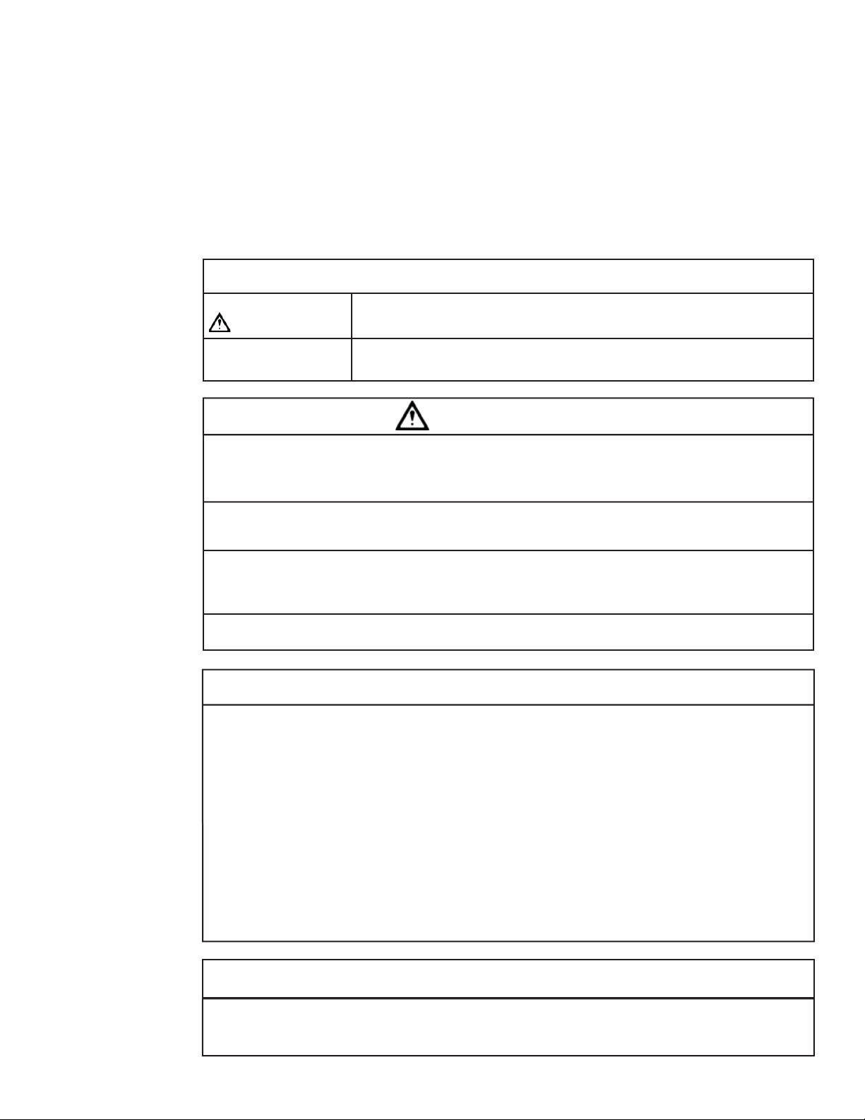
Space
Requirement
11”
(27.9 cm)
7 3/4”
(19.7 cm)
16 11/16”
(42.4 cm)
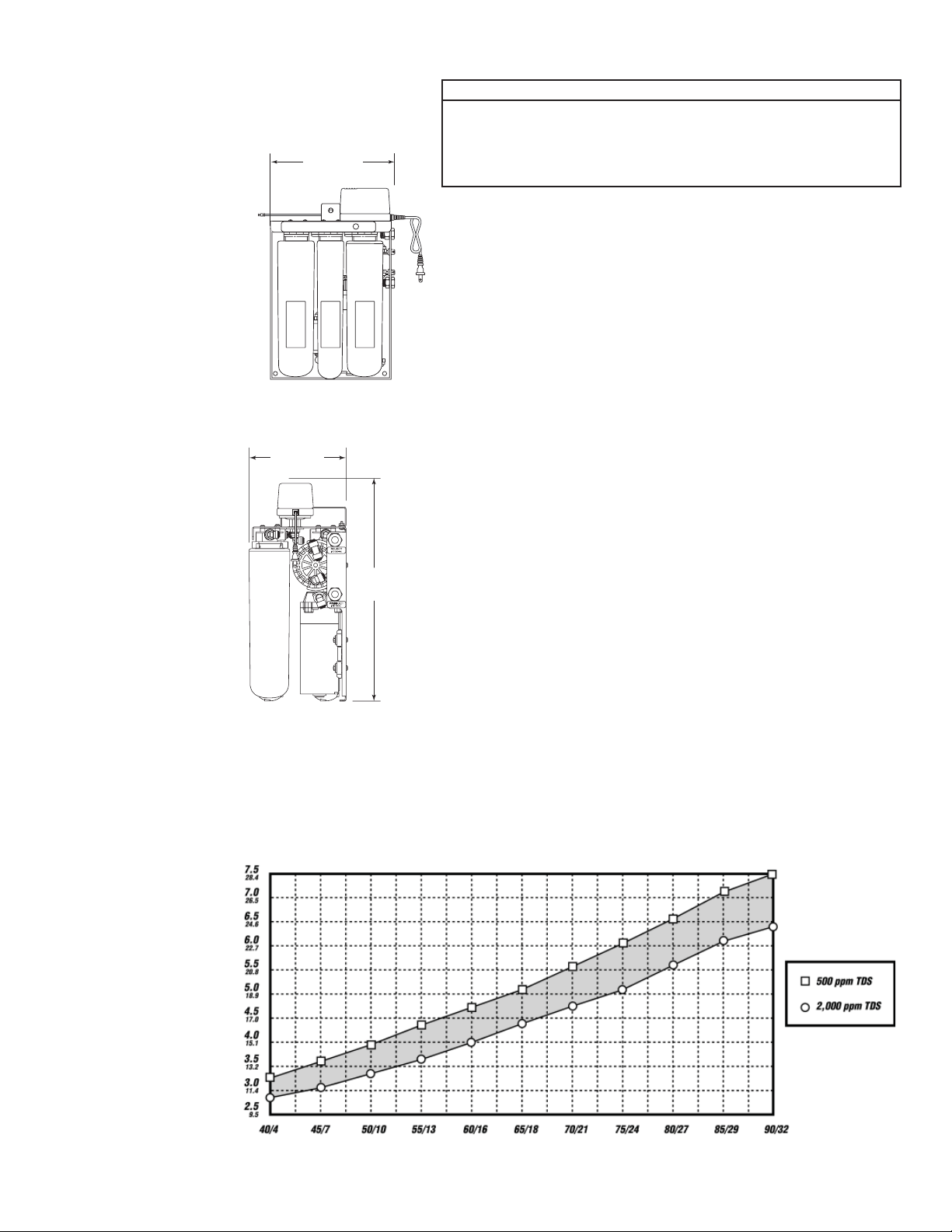
ScaleGard Plus 2 - Estimated Water Production
Important: Installation Requirements
CAUTION
To reduce the risk associated with property damage due to water
leakage:
• Installation must comply with existing state or local plumbing codes;
• Read and follow Use Instructions before installation and use of this
system.
Congratulations on your purchase of the CUNO Foodservice ScaleGard
PLUS 2 water treatment system. The ScaleGard PLUS 2 systems utilize
some of the world’s most advanced scale and corrosion control technologies in a compact, highly efficient package.
The ScaleGard PLUS 2 system is designed for food service equipment
with low water draw such as steam kettles and tables, combis, electric
and gas steamers, misters or other applications, where water consumption does not exceed 6 gph (22.7 lph) continuous. See estimated water
production chart below.
The ScaleGard PLUS 2 STM150 is recommended where a minimal
TDS level is required for proper equipment operation. The ScaleGard
PLUS 2 TSR150 is recommended for applications where zero hardness
is required such as proofing ovens, flash steamers, injection steamers
and misters.
Before beginning the installation, take a few minutes to familiarize yourself with the system by reviewing the entire installation, operating and
maintenance manual. It is also important to review the criteria below
to make sure that the requirements have been or will be met when the
installation is complete. Be sure to confirm that the feedwater falls within
the limits shown below. If you’re not sure if this has been done, check
with your distributor before installing the system. This is important
because failures caused by water related problems are not covered
under the system warranty.
Installation must comply with state and local plumbing requirements.
Feedwater Parameters:
Feed TDS . . . . . . . . . . . . . . . .Up to 2000 ppm (mg/L)
Hardness* . . . . . . . . . . . . . . . .< 10 grains (171 mg/L)
Iron (Fe) . . . . . . . . . . . . . . . . . .< 0.1 mg/L
Hydrogen Sulfide . . . . . . . . . . .none allowable
Feed pH . . . . . . . . . . . . . . . . . .4-11
Free chlorine . . . . . . . . . . . . . .< 2 mg/L
Manganese(Mn) . . . . . . . . . . .< 0.05 mg/L
Turbidity . . . . . . . . . . . . . . . . . .< 5 NTU
* Note: For waters over 10 grain hard, a CUNO water softener is recommended
for pretreatment. Consult CUNO technical services for correct sizing.
Electrical Requirements:
Confirm that transformer is compatible with available electrical power
supply.
™
Water Production (Gallons Per Hour/Liters Per Hour)
Feedwater Temperature (°F/°C)
3
Page 5

ScaleGard™ PLUS 2 Installation Schematic
telnI
y l p p
u S
retaW
e v l a V
Additional
Plumbing
Connections
(not supplied)
• Manual Bypass:
A manual bypass loop is
recommended to facilitate
proper service of the filter
system.
• Drain Line:
A drain line is recommended to depressurize the
system during cartridge
changeout, for sanitizing
the system, and for draining the tank. Note: 10, 20,
and 40 gallon (38, 76, 151
liter) tanks are capable of
draining water in excess
of 13 gpm (49 lpm). Drain
connection must be sized
accordingly.
Service Shut
V d i o n e l o S s s a p y B
m e t s y S O R
0 5 1 M T S
s u l P v e B
s m e t s y S R S T
O R " 8 / 3
n i a r D
. y s s A e v l a
s s a p y B l a u n a M
) l a n o i t p O (
e n i L r e t a W
k n a T O R
k n a T l a u n a M
e v l a V
n/Sample ValveiarD knaT
Off Valve
(Optional)
e v l a V k c e h C
If your water analysis indicates that any of these parameters are not in
range, additional pretreatment or higher frequency of maintenance may
be required. Contact your distributor for assistance. The presence of
silica or flocculants (e.g. alum or cationic polymers) in the feedwater
can cause membrane fouling and may require special chemical pretreatment or periodic membrane cleaning.
Operating Parameters:
Typical TDS Cartridge Rejection .....>95%
Feed Temperature ...........................40-100°F (4-38°C)
Feed Pressure .................................20-65 psi (138-448 kPa)*
Production .......................................... Chart on page 3 shows output in
gallons per hour at varying water
temperatures. Actual output may
vary according to feedwater
conditions and membrane variations.
Note: For water temperature below 50°F (10°C) water can be
preheated to improve production rate.
ec i v r e S o T
• Pressure Gauge:
A pressure gauge in the
product water line is recommended to determine
the system’s performance
and when the system is
de-pressurized.
CAUTION
*To reduce the risk associated with property damage due to water
leakage:
• Do not install on systems where line pressures above 65 psi (448
kPa) may occur. Line water pressure in excess of 65 psi will require installation of a pressure regulator prior to the unit.
4
Page 6

Installation Procedure
CAUTION
To reduce the risk associated with property damage due to water leakage:
• Installation must comply with existing state or local plumbing codes;
• Read and follow Use Instructions before installation and use of this system.
Positioning Equipment
Prior to installing the ScaleGard™ PLUS 2 system, review the installation schematic (page 4) and carefully
plan the installation location for all system components. Obtain all additional hardware for plumbing connections. This will help provide proper positioning and improve serviceability during routine maintenance.
1. Position the storage tank in desired location. (See storage tank installation procedure, page 6.)
2. The ScaleGard PLUS 2 system should be installed within 15 ft (4.6 m) of the storage tank.
3. The ScaleGard PLUS 2 system must be installed within 6 ft (1.8 m) of an electrical outlet. The bypass
solenoid valve should be installed within 6 ft. (1.8 m) of the storage tank.
4. All components should be accessible and have at least 6 inches (15 cm) of clearance on all sides of
ScaleGard PLUS 2 system to facilitate servicing.
5. Access to feedwater and drain connection are also required.
Wall Mounting the Filter System
The filter system weighs approximately 30 lbs. (13.6 kg) and must be mounted securely to a rigid surface.
There are two additional mounting holes on both sides of the booster pump at the bottom of the bracket if
needed. System must be installed vertically.
1. Determine the desired mounting location and using the supplied template, mark mounting hole locations.
2. Install the three mounting screws in the marked locations, leaving about an 1/8” (3.2 mm) from the wall.
3. Remove the cartridges from the filter system by turning to the left 1/4 turn and pull down to remove.
4. Lift the filter system and align the keyhole slots over the mounting screws. Tighten the screws, securing the
filter system to the wall. Note: You may have to slide the permeate pump to the left to fully expose the
right mounting hole.
5. Install the cartridges. Note: Mate the head
icon letter with the cartridge icon letter
(S, C, M, T or H). The TDS filter (M) has
a John Guest® fitting for reject water.
Attach reject tubing to the fitting (as
shown in drawing below).
6. Mount the transformer to the bracket with
screws provided to the top right side of the
bracket.
Feedwater Connection
The feedwater supply line is 3/8” O.D. tubing
and should not exceed 20 ft (6.1 m) from the
main feedwater connection to the filter system.
For longer distances, 1/2” pipe or larger should
be brought to within 20 ft (6.1 m) of the system.
Important: Connect to an adequate water
supply having a minimum 20 psi (138 kPa) and
maximum 65 psi (448 kPa) pressure at the inlet
of the filter system.
To reduce the risk associated with property
damage due to water leakage:
• Do not install on systems where line pressures
above 65 psi (448 kPa) may occur. Line water
pressure in excess of 65 psi will require installation of a pressure regulator prior to the unit.
1. Connect a shut-off valve to main water line.
Under no circumstances should a needle
valve or self piercing valve be used.
2. Run a 3/8” O.D. line from the feedwater
connection at the main water line to the water
inlet on the filter system. Inlet connection is a
3/8” John Guest fitting.
CAUTION
TDS Filter M
(RO Module)
5
Reject
Tu be
Plug
IMPORTANT: Remove white
plug from module and insert
black tube as shown. Insert
RO module into fi lter head
and rotate 1/4 turn until it
stops. The label should face
the front.
Permeate
Pump
Transformer
Connection
Page 7

The water pressure in
the tank will increase as
the tank fills with water.
When the pressure in the
tank reaches approximately 80 psi (552 kPa)
the filter system shuts off.
When water is drawn from
the tank and the pressure
drops to approximately 60
psi (414 kPa), the filter
system will automatically turn on.
Drain Connection
Important: An approved air gap should exist between the filter system
drain lines and the drain opening to meet local plumbing codes.
1. Run a minimum 3/8” O.D. tube from the reject port to the drain.
2. The 3/8” O.D. reject tubing line may be run up to 10 ft (3 m) from the
filter system to the drain. Care must be taken not to crimp or block the
reject tubing line.
Automatic Bypass Valve
The auto-bypass valve has 3/8” MNPT inlet and outlet ports and a 6’ (183
cm) power cord that plugs into the filter system. This auto-bypass valve
should be installed between the incoming unfiltered water line to the filter
system and the water line to service after check valve. (Refer to page 4.)
If the tank pressure drops
to 40 psi (276 kPa) the
auto-bypass solenoid valve
will open allowing unfiltered
water to flow to service
until tank pressure reaches
approximately 60 psi (414
kPa). When the filter system is in auto-bypass the
red light on the front of
the bracket will come on.
NOTE: TSR150-2/2A/2B
Bypass at 20psi (138
kPa) to 40 psi (276 kPa).
IMPORTANT!
The use of metallic piping
materials for high quality
water is not recommended because the water is
aggressive due to low TDS
and pH. Plastic tubing and
pipe are most suitable.
Solvent bonded plastic pipe
should be assembled carefully to avoid excessive glue
inside the pipe. Piping of
any type should be flushed
thoroughly before use. Be
sure piping conforms to
local plumbing codes.
Storage Tank Installation
Note: Storage tanks are purchased separately. Consult the CUNO®
Foodservice Price List for applicable sizes and part numbers.
1. Follow installation instructions provided with tank.
2. Check the air pressure in the tank at the valve in the top of the tank.
With the tank empty, the pressure should be 20 psi (137.9 kPa).
Adjust the air pressure as required.
3. Place the tank in the desired location. It should be placed in an area
where it will not be bumped or jarred.
4. Connect fitting and minimum 3/8” O.D. tubing to product port of the unit.
5. Run tubing from the other side of the TEE to the check valve and
on to point of use connection and bypass line. Refer to Installation
Schematic on page 4.
6. Open the ball valve on the tank by turning the handle until it is parallel
with the body of the valve.
Storage Tank Diameter Height Pipe Connection
2.5 gal. (9.5 lit.) 9 1/16" (23 cm) 14 1/8" (35.9 cm) 1/4" (0.6 cm)
5 gal. (19 lit.) 15 3/8" (39.1 cm) 17 3/8" (44.1 cm) 3/4" (1.9 cm)
10 gal. (38 lit.) 16" (40.6 cm) 32 1/2" (82.6 cm) 1" (2.5 cm)
20 gal. (76 lit.) 16" (40.6 cm) 57 1/2" (146.1 cm) 1" (2.5 cm)
40 gal. (151 lit.) 24" (61 cm) 56 1/2" (143.5 cm) 1 1/4" (3.2 cm)
Point-of-Use Connections
Distance from Storage
Tank to Point of Use
up to 5 ft (0-1.5 m) 1/2" O.D. (1.3 cm) 3/8" (1 cm) Schedule 40 PVC
5-20 ft (1.5-6.1 m) 3/4" O.D. (1.9 cm) 1/2" (1.3 cm) Schedule 40 PVC
20-40 ft. (6.1-12.2 m) N/R 1/2" (1.3 cm) Schedule 40 PVC
40-60 ft. (12.2-18.3 m) N/R 3/4" (1.9 cm) Schedule 40 PVC
Note: The above table is appropriate for point of use applications that require flow
rates up to 5 gpm (18.9 lpm).
Select the tubing or pipe size that will help provide adequate flow and pressure to the
point of use (i.e. Longer runs require larger tubing).
The type of tubing or pipe used must conform to local plumbing codes. Tubing or pipe
used for drinking water applications must be NSF listed or made of FDA compliant
materials.
Recommended Minimum
Tubing Size
Recommended Minimum
Plastic Pipe Size
6
Page 8

Start-Up Procedure
1. Check air pressure in the storage tank, Refer to Storage Tank Installation. (page 6)
2. Close all water valves (5) in the system. (page 4)
3. Open water supply valve at the connection to the main water feed and the inlet water valve at the
unit. If manual bypass is installed it should be in the filter position.
4. Plug in transformer.
5. Plug bypass solenoid into the filter system.
6. Open the drain/sample valve. This will purge the air from the system. When you see a steady
stream of water close the drain/sample valve.
7. Open the ball valve on the storage tank.
8. Inspect all connections, fittings in the system for leaks, repair as necessary.
9. Allow storage tank to fill with RO water. NOTE: see chart for required times to fill storage tanks.
10. Open valve in water line to service and flush feed lines to each point of use.
11. System is now ready to use.
Tank Capacity
2.5 gal. (9.5 lit.) 0.4 - 0.5 hour
5 gal. (19 lit.) 0.9 - 1.1 hours
10 gal. (38 lit.) 1.8 - 2.1 hours
20 gal. (76 lit.) 3.6 - 4.2 hours
40 gal. (151 lit.) 7.2 - 8.4 hours
@ 70°F (21°C) Water Temperature
Time Required
To Fill Tank
Routine Maintenance
CAUTION
To reduce the risk associated with property damage due to water leakage:
• Installation must comply with existing state or local plumbing codes;
• Read and follow Use Instructions before installation and use of this system.
De-pressurization Procedure
1. Turn off the inlet water valve.
2. Close the tank ball valve.
3. Open the drain line valve.
4. Wait for 30 seconds, then unplug the transformer. System is now de-pressurized.
Caution: Tank will still be under pressure.
Sediment Filter (S)
Replacement Procedure [6-12 months]
1. De-pressurize the system as instructed above.
2. Locate the sediment filter. To remove the sediment filter, turn to the left 1/4 turn. Pull down to remove
and discard it.
3. Insert the new filter by aligning the tabs with the filter head. Push up to insert and turn to the right
1/4 turn.
Chlorine Reduction Filter (C)
Replacement Procedure [6-12 months]
1. De-pressurize the system as instructed above.
2. Locate the chlorine reduction filter. To remove the chlorine reduction filter, turn to the left 1/4 turn.
Pull down to remove and discard it.
3. Insert the new filter by aligning the tabs with the filter head. Push up to insert and turn to the right
1/4 turn.
7
Page 9

TDS Reduction Filter (M)
Replacement Procedure [annually]
1. De-pressurize the system as instructed above.
2. Locate the TDS reduction filter. To remove the TDS reduction filter, turn to the left 1/4 turn. Pull down
to remove.
3. Disconnect reject tubing by pushing in the white collet on plastic fitting to release the tubing (see page
9). Discard the used cartridge.
4. Remove the plug from the plastic fitting on the new cartridge and connect the reject tubing.
5. Insert the new filter by aligning the tabs with the filter head. Push up to insert and turn to the right 1/4 turn.
Note: The first full tank of water filtered after the filter is replaced should be discarded.
See start-up procedure, page 7.
Hardness Reduction Filter (H)
(ScaleGard™ PLUS 2 TSR150) Replacement Procedure [6-12 months]
1. De-pressurize the system as instructed above.
2. Locate the hardness reduction filter. To remove the hardness reduction filter, turn to the left 1/4 turn.
Pull down to remove and discard it.
3. Insert the new filter by aligning the tabs with the filter head. Push up to insert and turn to the right 1/4 turn.
Note: The first full tank of water filtered after the filter is replaced should be discarded.
See start-up procedure, page 7.
TDS Adjustment Filter (T)
(ScaleGard PLUS 2 STM150) Replacement Procedure [6 months]
1. De-pressurize the system as instructed above.
2. Locate the TDS adjustment filter. To remove the TDS adjustment filter, turn to the left 1/4 turn. Pull
down to remove and discard it.
3. Insert the new filter by aligning the tabs with the filter head. Push up to insert and turn to the right 1/4 turn.
Note: The first full tank of water filtered after the filter is replaced should be discarded.
See start-up procedure, page 7.
Restarting and Purging the RO System
1. Turn on inlet water valve.
2. Make sure the tank ball valve is closed.
3. Open the drain/sample valve
4. Plug in the transformer and wait for a steady stream of water to come from the drain/sample valve.
This will purge the air from the system.
5. Close the drain/sample valve and wait for pump to shut off (this will pressurize system). Check for leaks.
6. Open tank ball valve.
7. Plug in bypass solenoid valve.
8
Page 10

‘Push-In’ Tubing Connector
(John Guest® Fitting)
This product is outfitted with user friendly “Push
In” connectors. Proper use of the connectors is
shown in the diagrams. It is most important that
the tubing selected for use with these connectors
be of high quality, exact size and roundness, and
with no surface nicks or scratches. If it is necessary to cut the tubing, use a plastic tubing cutter
or sharp razor knife. Make a clean square cut.
Should a leak occur at a ‘Push In’ connector, the
cause is usually defective tubing.
To fix leaks:
• Relieve pressure.
• Release tubing.
• Cut off at least 3/8” (9.5 mm) from end.
• Reattach tubing.
• Confirm connection is leak free.
To Attach Tubing
1
Tube
Grey Collet
Push tubing straight in as far as it will go.
To Release Tubing
1
2
Tubing is secured in.
2
Push in grey collet to release tubing.
Pull tubing straight out.
ScaleGard™ PLUS 2 Electrical Wiring Diagram
Bypass Pressure Switch
(Red Terminals)
Tank Pressure Switch
(Blue Terminal)
Bypass
Light
Solenoid
Automatic
Bypass
Solenoid
Fuse
Holder
Booster Pump
Transformer
Installation Components for ScaleGard™ PLUS 2 Systems*
• 1 pc of 3/8” Cross • 1 pc of 1/4” x 3/8” Male Connector
• 1 pc of 3/8” x 1/4” Reducer Bushing • 1 pc of 1/4” NPT 0-160 pressure gauge
• 6 pcs of 1/2” x 3/8” Male Connector • 1 pc of 3/8” Female Pipe Tee
• 1 pc of 3/8” Female Ball Valve • 1 pc of 3/8”x1” Reducer Bushing
• 3/8” Nipple • 3/8” Tubing
• 1/2” Tubing (optional) • Cutter or sharp razor knife.
* Not Provided With System
9
Page 11

ScaleGard™ PLUS 2 System Part List
Item # Description STM150 TSR150-2
1 Sediment Filter (S) 55997-01 55997-01
2 Chlorine Reduction Filter (C) 55995-01 55995-01
3 TDS Reduction Filter (M) 55987-07 55987-07
4 Ion Media Filter (T) 55998-01 -
4 Hardness Reduction Filter (H) - 55996-01
5 Permeate Pump 89-1331202 89-1331202
6 Pump / Fuse Assembly 53-41401 53-41401
7 Solenoid Valve 60-1213201 60-1213201
8 Brine Flow Control 53-52001 53-52001
9 Bypass Solenoid Valve Assembly (60 Hz) 50-025 50-025
9 Bypass Solenoid Valve Assembly (50 Hz) 50-026 50-026
10 Transformer (115V/60 Hz) 25-63031 25-63031
10 Transformer (230V/50 Hz) 25-63032 25-63032
10 Transformer (100V/50 Hz) 25-63030 25-63030
Not Shown Tank Switch (blue plug) 25-15505 25-15505
Not Shown Bypass Switch (red plug) 25-15503 25-15502
Not Shown Fuse, 2 Amp, 3AGC-250V 25-61225 25-61225
10
9
TSR150-4
55997-01
55995-01
55987-07
-
55996-01
89-1331202
53-41401
60-1213201
53-52001
50-025
50-026
25-63031
25-63032
25-63030
25-15505
25-15503
25-61225
8
5
7
4
3
2
1
Front View Front View without Front Cartridges
10
6
Page 12

Limited Two Year Warranty
CUNO Incorporated warrants the original purchaser-consumer of its Product that is free of defects in materials and
workmanship. Any defect, malfunction, or other failure of the
Product to conform to this warranty will be remedied by CUNO
in the manner provided below.
This Warranty, together with any warranties implied by law,
shall be limited to a duration of two (2) years from the original
date of purchase by the consumer.
This Warranty does not apply to defects that result from
abuse, misuse, alteration or damage not caused by CUNO.
IMPORTANT: To file a claim under this warranty you must
complete and mail the Warranty Registration Card supplied with
this product to CUNO at the address below within ten (10) days
of original purchase date.
THIS WARRANTY DOES NOT COVER, AND IS INTENDED
TO EXCLUDE ANY LIABILITY ON THE PART OF CUNO,
WHETHER UNDER THIS WARRANTY OR UNDER ANY
WARRANTY IMPLIED BY LAW, FOR ANY INDIRECT OR
CONSEQUENTIAL DAMAGES FOR BREACH HEREOF OR
THEREOF.
Note: Some states prohibit limitations on the duration of
implied warranties and on the exclusion of indirect or consequential damages; and so the limitation on implied warranties
and on incidental and consequential damages may not be applicable to you.
RESPONSIBILITY OF CUNO
CUNO’s responsibility under this warranty shall be to repair
at its expense, at no charge to the original purchaser-consumer,
any product that is actually defective, malfunctioning, or otherwise in violation of this warranty. If CUNO for any reason
cannot repair a Product covered hereby within two (2) weeks
after receipt of the original purchaser-consumer’s notification
of a Warranty claim, then CUNO’s responsibility shall be, at its
option, either to replace the defective Product with a compa-
rable new unit at no charge to the consumer or to refund the full
purchase price. CUNO’s obligations of repair, replacement, or
refund are conditioned upon return of the defective Product to
CUNO.
If any Product covered hereby is actually defective within the
terms of this Warranty, then CUNO will bear all the reasonable
and proper shipping and mailing charges actually incurred in the
consumer’s return of the Product set forth herein. If the Product
proves not to be defective within the terms of this Warranty, then
all costs and expenses in connection with the processing of the
consumer’s claim hereunder shall be borne by the consumer.
RESPONSIBILITY OF THE CONSUMER
The original purchaser-consumer’s sole responsibility in the
instance of a warranty claim shall be to notify CUNO of the
defect, malfunction, or other manner in which the terms of this
Warranty are violated. You may secure performance of obligations hereunder by (in writing):
1. Identifying the Product involved (by model or serial number
or other sufficient description that will allow CUNO to determine
which product is defective).
2. Specifying where, when, and from whom the Product was
purchased.
3. Describing the nature of the defect, malfunction, or other
violation of this Warranty.
4. Sending such notification together with the defective Product
and $5.00 check or money order to cover postage and handling
to:
CUNO Incorporated,
400 Research Parkway, Meriden, Connecticut 06450, USA
THIS WARRANTY GIVES YOU SPECIFIC LEGAL RIGHTS,
AND YOU MAY ALSO HAVE OTHER RIGHTS, WHICH VARY
FROM STATE TO STATE
CUNO and ScaleGard are trademarks of 3M Company used under license.
John Guest is a trademark of John Guest International Limited.
© 2007 3M Company. All rights reserved.
a 3M company
CUNO Incorporated
400 Research Parkway
Meriden, CT 06450, USA
Toll Free: 1-888-218-CUNO
Worldwide: 203-237-5541
Fax: 203-238-8701
www.cunofoodservice.com • www.cuno.com
 Loading...