

Page 1

292
Page 2

4. Specialty Connectors
293
4
www.3MTelecommunications.com
Content
Specialty Connectors
page
4.1 Connectors for PCB applications
QuanteTMSJS 294 - 295
QuanteTMSIDTM-P/SIDTM-CP 296 - 299
4.2 Technical modules
QuanteTMSTGT 300 - 303
4.3 Modules for large cables
QuanteTMRGT 304 - 305
4.4 Bus termination unit
QuanteTMS28 306
4.5 Screwtype Strips/Boxes
QuanteTMConnection Strips 307
QuanteTMTRP, QuanteTMB12P 308 - 309
QuanteTMDistribution Boxes 3-6 pair 310
QuanteTMDE Screwtype 311 - 312
QuanteTMBR2 313
Page 3
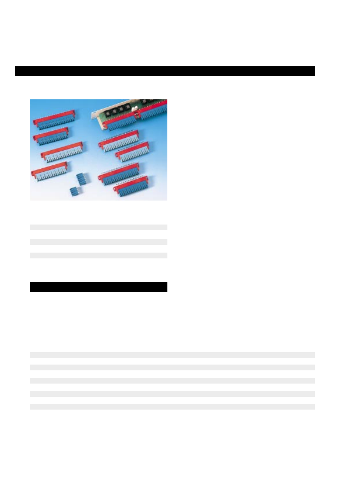
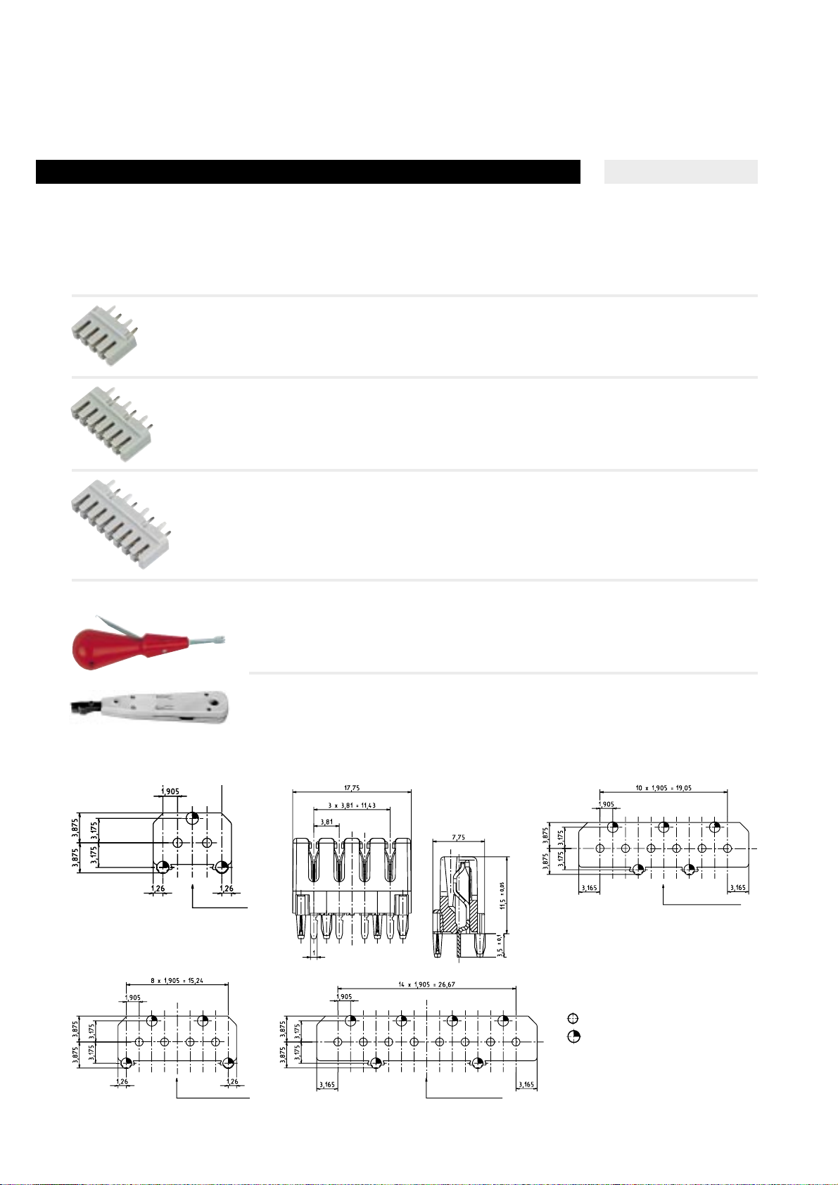
SJS modules for PCB mount are designed to interface twisted
copper wires to any PCB. Using the STG straight IDC contact
design, SJS modules can accomadate all wires in the range from 0,4
to 0,8 mm. As a result the overall dimensions for the range of
modules are very compact.
The range consists of 8 and 10 pair strips with straight or angled
soldering pins which provide flexibility when positioning the SJS
strips on the PCB.
SJS is also available in 2 and 3 pair strips, which can fit together in
order to build higher capacity. The soldering pins are straight for
these versions.
8 and 10 pair strips offer addtionnal side holes to secure the
mounting on the PCB with 2 screws.
SJS are compatible with all accessories of the STG range.
The protection solution to be used with SJS strips is the multipair
protection magazine with earth cord.
• The SJS C2 disconnection strips provide disconnection and
testing facilities using plugs of the STG modules. They allow the
insertion of an item into a circuit in series or in parallel.
• The multipurpose IDC tool is used for wiring up SJS strips as
well as terminal blocks and cable-head blocks from the QuantePouyet products range.
• SJS connection strips can be used in any application involving
electronics - in telephony switching systems for example.
Dimensions W H D
SJS A2 2 p straight 21,3 18 10
SJS A2 3 p straight 31,3 18 10
SJS 8 p straight 100 32,4 10
SJS 8 p angled 100 13 36
SJS 10 p straight 120 32,4 10
SJS 10 p angled 120 13 36
Quante SJS Strip for PCB
4.1 Connectors for PCB applications
Quante
TM
SJS
Description
294
Highlights
• Straight IDC technology
• Compact
• Straight or angled pins
Module type No of IDC contacts No of solder pins Drilling diameter Drilling intervall
SJS A2, 2 pair, straight outlet 8 8 1,4 mm 5,08 mm
SJS A2, 3 pair, straight outlet 12 12 1,4 mm 5,08 mm
SJS A2, 8 pair, straight outlet 32 32 1,4 mm 5 mm
SJS A2, 8 pair, angled outlet 32 32 1,4 mm 5 mm
SJS A2, 10 pair, straight outlet 40 40 1,4 mm 5 mm
SJS A2, 10 pair, angled outlet 40 40 1,4 mm 5 mm
SJS A2, 8 pair, straight outlet 32 16 1,4 mm 5 mm
SJS A2, 8 pair, angled outlet 32 16 1,4 mm 5 mm
SJS A2, 10 pair, straight outlet 40 20 1,4 mm 5 mm
Page 4
SJS C2 module, 8 pairs, straight outlet C220744A0000
SR
SJS C2 module, 8 pairs, angled outlet C220775A0000
DR
SJS C2 module, 10 pairs, straight outlet C220743A0000
SR
SJS C2 module, 10 pairs, angled outlet C220779A0000
DR
SJS A2 module, 2 pairs, straight outlet C220756A0000
SJS A2 module, 3 pairs, straight outlet C220758A0000
SJS A2 module, 8 pairs, straight outlet C220741A0000
DR
SJS A2 module, 8 pairs, angled outlet C220773A0000
DR
SJS A2 module, 10 pairs, straight outlet C220740A0000
DR
SJS A2 module, 10 pairs, angled outlet C220777A0000
DR
Quante SJS Modules, without disconnection, Tool-type IDC
295
4.1 Connectors for PCB applications
Quante
TM
SJS
Ref.-No.Type/Order text
4
Specific Connectors
SR = singel row
DR = double row
Quante SJS Modules, with disconnection, Tool-type IDC
Page 5
Type SID-P/3.81 SID-P/5.08 SID-CP/4.0
Pitch 3.81 mm 5.08 mm 4.0 mm
Poles 2,4,6,8 3,4 20
Wire diameter 0.32 mm - 0.64 mm 0.40 mm - 0.80 mm 0.32 mm - 0.80 mm
4.1 Connectors for PCB applications
Quante
TM
SIDTM-P/SIDTM-CP
Description
296
Highlights
QuanteSID-P Strip for PCB
SID-CP/4.0
SID-P/5.08
• Inter nationally proved SID technology
• Stripping, terminating and cutting to size in one progress
• Can be connected with screwdriver (3 mm)
• Compact design
• SID-P is compatible with LSA+ footprint.
SID-P/3.81
The SID-P product range has been specifically designed for applications using printed circuit boards, and consists of three versions:
SID-P/3.81, SID-P/5.08 and SID-PD/4.0.
The internationally proved SID achieves safe contact in one process, without having to strip, cut wire to size and without the use
of special tools.
SID-P strips can also be connected using the cost-efficient SID
insertion tool, or alternatively, the LSA Plus tool can be used on
the SID-P/3.81version.
Due to the compact design of the SID-P strips easy connection
can be achieved, even within the most restricted of spaces. This
‘compactness’ can be of particular advantage within areas which
require connections under restrictions ratios, for example, in wall
outlets or when mounting active components in housings.
Quante SID-P Features
Page 6
Connection side
10,16
5,08
2,5
2,54
2,54
2,5
3,25
2,54
3,95
SID-P3 5.08
connecting strips, 3-pole
PU: 100 pcs. Weight: 0.190 kg 60178-507 00
PU: 1000 pcs. Weight: 1.9 kg 60178-507 25
SID-P4 5.08 60178-508 25
connecting strips, 4-pole
PU: 1000 pcs. Weight: 2.5 kg
Accessories
SID-standard tool 79397-512 00
Connection tool for SID-P 5.08
297
4
4.1 Connectors for PCB applications
Quante
TM
SIDTM-P/SIDTM-CP
Ref.-No.Type/Order text
Specific Connectors
Technical characteristics
QuanteSID-P/5.08, Strip for PCPB
Soldering pin holes Ø 1.2
Centering holes Ø 1.5
Centering holes Ø 1.8
6
1
5,08
12,5
4,3
4,3
5,085,08
Hole pattern symbols SID-P/5.08
SID-P3 5.08 SID-P4 5.08
The plastic retaining pegs on the SID-P / 5.08 connection terminals
are used to locate and secure the strip within the corresponding
apertures in the PCB. These are then ultrasonically welded or hot
riveted in place, depending on requirements.
(See drawing)
Connection side
15,24
2,5
2,54
2,54
5,08
2,54
2,5
3,25
3,95
Page 7
SID-P2 3.81 60178-514 00
connecting strips, 2-poles, unprinted version
PU: 1000 pcs. Weight: 0.8 kg
SID-P4 3.81 60178-511 00
connecting strips, 4-poles, unprinted version
PU: 1000 pcs. Weight: 1.3 kg
SID-P6 3.81 60178-512 00
connecting strips, 6-poles, unprinted version
PU: 1000 pcs. Weight: 1.9 kg
SID-P8 3.81 60178-510 00
connecting strips, 8-poles, unprinted version
PU: 1000 pcs. Weight: 2.5 kg
Quante SID-P Accessories
Connection tools for SID-P 3.81
SID-standard tool 79397-512 00
QSA-standard tool 79397-500 40
Ref.-No.Type/Order text
4.1 Connectors for PCB applications
Quante
TM
SIDTM-P/SIDTM-CP
298
Soldering pin holes Ø 1.2 + 0.1mm
Hole pattern symbols SID-P/3.81
Peg holes Ø 1.6 +- 0.05 mm
Connection side
Connection side
Connection side
Connection side
Quante SID-P / 3.81 Strip for PCB
SID-P2 3.81
SID-P4 3.81
SID-P6 3.81
Page 8
SID-CP disconnection module with earthing 79103-573 00
for overvoltage protection
20 poles; PU: 10 pcs. Weight: 0.4 kg
SID-CP switching module without earthing 79105-506 00
40 poles
PU: 10 pcs. Weight: 0.4 kg
Earthing elements 79114-556 00
PU: 20 pcs.
Quante SID-CP Protection for overvoltage solutions
3-pole overvoltage protection magazine, 10 pairs 79126-511 00
Single Pair Protection (SPP), 1 pair
SPP G B2 230 V/G 79104-505 00
SPP GS B3 230 V/GS 79104-508 00
SPP GFS B3 185 V/GFS 79104-507 00
Earthing bar for SPP 79114-544 00
Quante SID Accessories
4 pole test lead 79054-567 00
SID standard tool 79397-512 00
SID-comfort tool 79397-519 00
scissors acting
PU: 1 pce. Weight: 0.070 kg
299
4
4.1 Connectors for PCB applications
Quante
TM
SIDTM-P/SIDTM-CP
Specific Connectors
Ref.-No.Type/Order text
Bore symbols for SID-CP/4.0
Soldering pin bore Ø 1.2 + 0.1 mm
Fastening bore Ø 4.3 mm
Quante SID-CP Strip for PCB
Page 9

4.2 Technical modules
Quante
TM
STGT
Description
300
Highlights
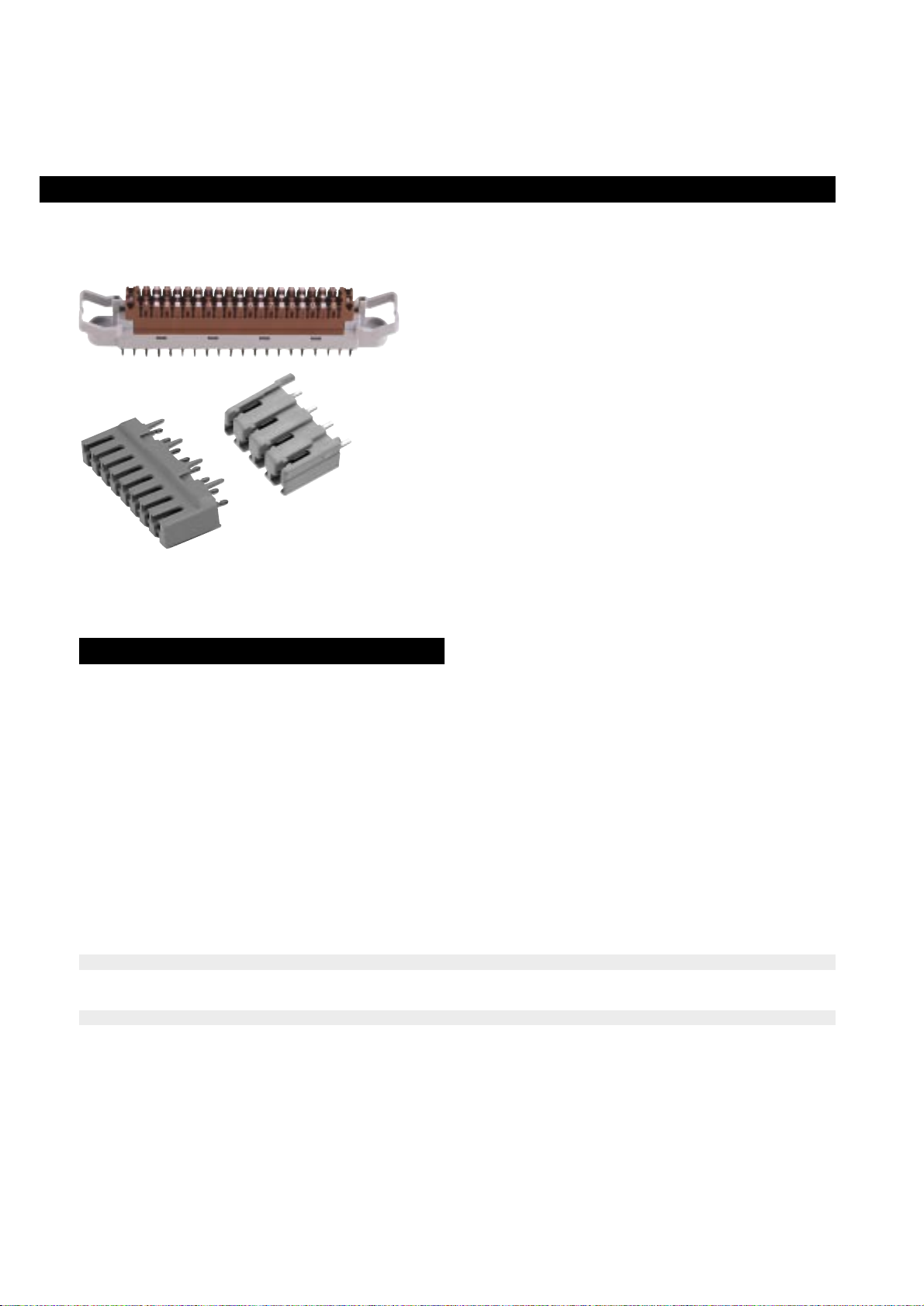
• Interchangeable Quante STGT Technical Modules are fitted with
removable electronic boards. This range therefore offers a
complete solution for protection, display, adaptation, etc.
• In case of maintenance, the electronic board can be replaced
without having to un-cable the module. Spare boards are
supplied as accessories.
• Specific technical modules can be developed according to
your needs (please, consult us).
• STGT Technical Modules are designed to enable a fast instal
lation of interfaces between cables with various characteristics
(for example: a single-strand cable with a modular jack connector).
• STGT Technical Modules are universal; they make it possible
to gather in one single system, functions which were so far
dispatched through several locations within an installation.
They ensure protection against overvoltages and overcurrents,
display, re-routing of lines, etc.
• 10 pair STR M2 IDC disconnection module
• Possibility to disconnect, test and T-connection
• Conductor diameters from 0.4 mm to 0.8 mm
• Insulation diameter: max. 1.5 mm
• Mounting on a Europe profile, 10 or 8 pair base
• Dimensions: 2 pitches of 16 mm
• Possibility to mount in 14 mm steps (please contact us)
• Interchangeable boards
(*) 100 V/µs wave
(**) Common mode, 6 kV wave, 0.5/700 µs
Characteristics of protection modules C 239 635 A C 239 825 A C 239 830 A
C 239 630 A
Characteristics Reinforced protection for telephony Protection for datacommunications
4 pairs, 48 V 2 pairs, 12 V
Nominal voltage 170 V 48 V 12 V
Nominal current 250 mA 300 mA 300 mA
Pass band 1 MHz 10 MHz 20 MHz
Sparking voltage 230 V (*) 68 V (**) 18 V (**)
Instantaneous surge current (8/20 µs) 5 kA 10 times 5 kA 10 times 5 kA
Resistance in series with line 10 Ω
Page 10

Quante STGT Modules for external lines
301
4
4.1 Technical modules
Quante
TM
STGT
Ref.-No.Type/Order text
Specific Connectors
l
e
Dipole/display/protection modules
Direct mounting onto the line (*)
Module, 2 pair, base 8 pairs,
with board 126 x 30 x 50 C239660A0000
48 V, 10 MHz
Fuse-holder modules
Protection against overcurrent
Accommodates cylindrical
Ø 5 x 20 mm fuses (not supplied)
Base 8 pair
Module, 4 fuses, with board 126 x 30 x 50 C239700A0000
Base 10 pair
Module, 6 fuses, with board 146 x 30 x 50 C239705A0000
(*) Earthing is automatic while modules are clipped onto the profile, which must be connected to ground.
Reinforced protection modules for telephony Dimensions
Protection against overvoltage and overcurrent (*). W x H x D
Base 8 pair module, C239630A0000
4 lines, with board 126 x 30 x 50
Spare board C239912A0000
Base 10 pair module, C239635A0000
5 lines, with board 146 x 30 x 50
Spare board C239914A0000
Reinforced protection modules for computer networks.
Protection against overvoltage and overcurrent (*).
Base 8 pair module, C239825A0000
4 pairs, with board,
48 V, 10 MHz 126 x 30 x 50
Spare board C239930A0000
Module, 2 pair, with board, C239830A0000
12 V, 20 MHz 126 x 30 x 50
Spare board C239932A0000
Quante STGT Modules for external lines
e
jump
side
cable
side
cable
side
jumper
side
jumper
side
1
ENTREE / IN
2
S 1
C 1
P
R 2
VZ
S 2
1
R 1
L
SORTIE / OUT
2
Page 11

Ref.-No.Type/Order text
4.1 Technical modules
Quante
TM
STGT
302
Quante STGT Modules for external lines (cont´d)
Display modules
Direct mounting onto extension lines.
48 V PABX power supply. One two-tone diode per line for line-engagement display.
Base 10 pair
Module, 10 pairs, with board
– Common version 146 x 30 x 50 C239615A0000
+ Common version 146 x 30 x 50 C239625A0000
Modules for re-routing of lines
Switches 2 terminals or 1 dedicated extension directly
to telephone network, in case of PABX power cut.
Base 8 pair
Module, 8 pairs, with board
12 V version 126 x 28 x 50 C239720A0000
24 V version 126 x 28 x 50 C239710A0000
Base 10 pair
Module, 10 pairs, with board
12 V version 146 x 30 x 50 C239725A0000
48 V version 146 x 30 x 50 C239655A0000
Network line display module
Mounting onto one of the line. No polarity identification. Dimensions
One two-tone diode per line for line-engagement identification. W x H x D
Module, 10 pairs, with board 146 x 30 x 50 C239605A0000
ELS test modules for special lines
Used for testing of special lines by series connection or short-circuit,
cross connection or insulation, using a rotary switch.
France Telecom approved (840 18 D).
One-pair version (2 wires) 126 x 28 x 50 C239690A0000
Two-pair version (4 wires) 126 x 28 x 50 C239680A0000
One-pair version with return lead 126 x 28 x 50 C239790A0000
(50 cm with test plug)
Two-pair version with return lead 126 x 28 x 50 C239730A0000
(50 cm with test plug)
PABX application Modules
Page 12

16/16 module C239835A0000
Same potential for all wires.
(Marked: – 48 V)
8/16 module C239840A0000
Same potential for one wire per pair.
(Marked: + 48 V)
SUB D 25
25 pin male, in-line cabling 126 x 28 x 50 C239745A0000
25 pin female, in-line cabling 126 x 28 x 50 C239740A0000
2 modular jacks 126 x 28 x 50 C239770A0000
Straight cabling (ISO 8877)
RJ 45, 8 pins
2 modular jacks 8 pairs 126 x 28 x 50 C239780A0000
Straight cabling (ISO 8877)
RJ 45, 9 pins
4 coax baluns 8 pairs 126 x 28 x 50 C239800A0000
Allows passage from the pair to
RG 62 coaxial cable for IBM terminals,
type 3278, and cabling to be simplified
by use of the existing telephone pairs.
Base 10 pairs
5 modular jacks 146 x 30 x 50 C239820A0000
straight cabling, RJ 12 (4 points)
Module with board
Dimensions
Base 8 pairs W x H x D
SUB D 9
9 pin male, in-line cabling 126 x 28 x 50 C239765A0000
9 pin female, in-line cabling 126 x 28 x 50 C239760A0000
SUB D 15
15 pin male, in-line cabling 126 x 28 x 50 C239755A0000
15 pin female, in-line cabling 126 x 28 x 50 C239750A0000
303
4
4.1 Technical modules
Quante
TM
STGT
Ref.-No.Type/Order text
Specific Connectors
Data port Modules
1
2
3
4
5
MODULE
Modular
jack
Modular
jack
Modular
jack
Modular
jack
Modular
jack
4
3
2
1
4
3
2
1
4
3
2
1
4
3
2
1
4
3
2
1
PABX application Modules
Potential distribution Modules
Page 13
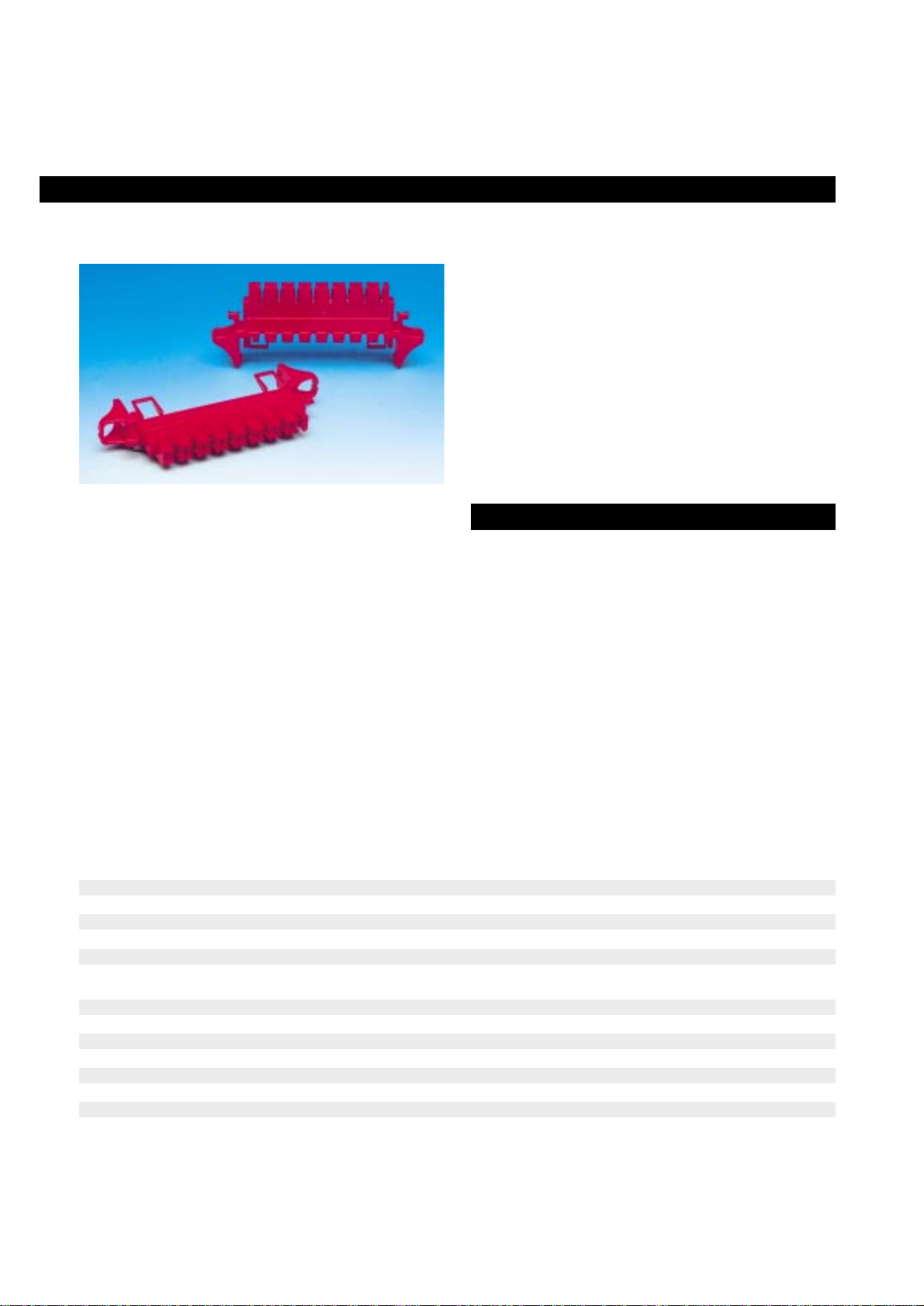
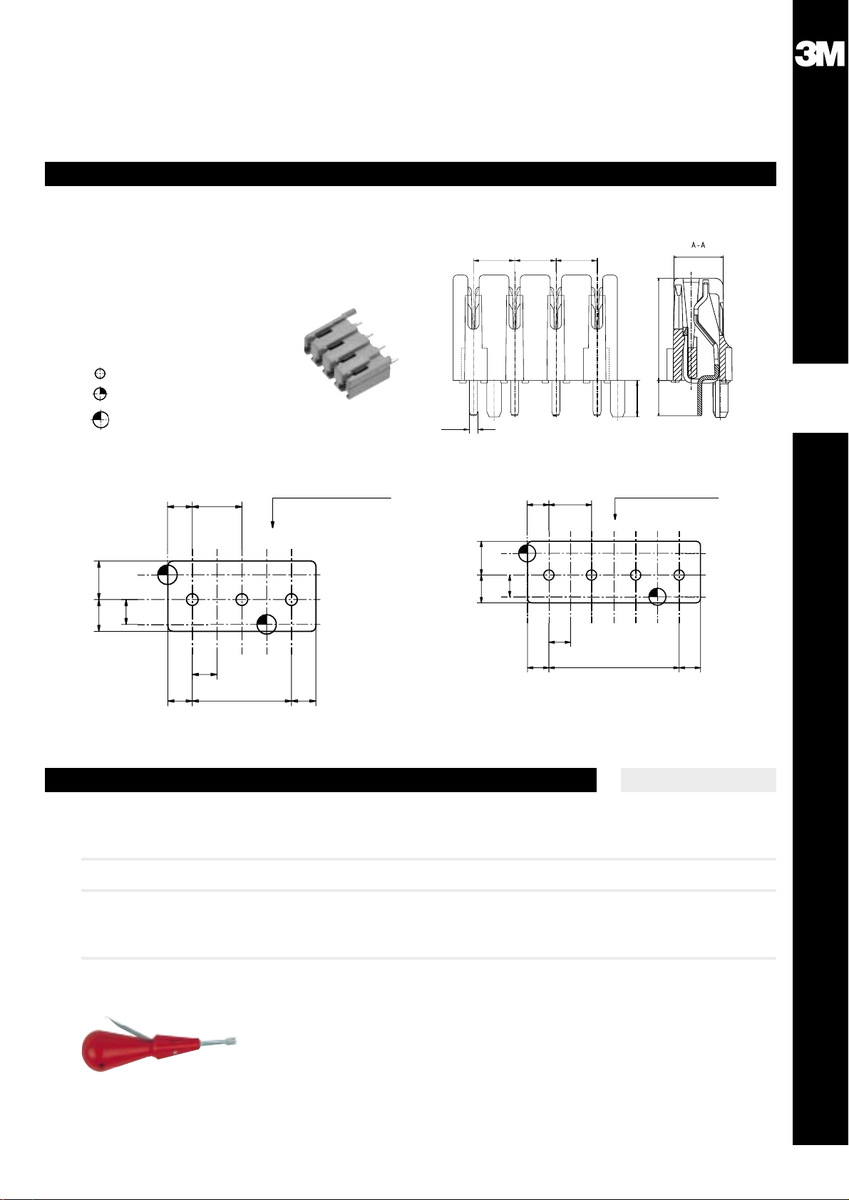
• RGT modules enable to complete several functions:
- Cabling of bus-structured networks, within distribution rooms
- Connection of cables with various diameters (transition module)
- Connection to one same potential
• The “Large Cable” insertion tool was especially designed to allow
for the connection of all modules in this range.
• This range of modules was especially designed for the connection
of conductors with “Large Diameters”:
- Insulation displacement contacts using a tool (IDC)
- 4 pair modules
- Connection of solid copper conductors with diameters
from 0.8 to 1.2 mm
- Disconnection wire by wire
- Test facility
- Accept single-wire or multi-wire conductors
- To be clipped on to standard EUROPE E8 and HPUL profiles
• Developed from the STG range, the RGT modules continue to
offer the following advantages:
- Extremely compact modules
- Reinforced insulation by use of self-extinguishible thermo
plastic materials
- Protection of contacts (totally insulated contacts)
- Common accessories to STG range:
- Disconnection plugs
- Label-holders and identification devices
- Wire-guide channels
4.3 Modules for large cables
Quante
TM
RGT
Description
304
Technical characteristics
4 pair module Dimensions
126 x 54 x 16 mm
Electrical characteristics
Contact resistance: < 1 mΩ
Leading-through resistance: < 5 mΩ (cable Ø 0.9 mm)
Insulation resistance: > 106 mΩ under 500 V
Dielectric strength: ≥ 6 kV efficient - 50 Hz
Accepted current: 10 A under 220 V
Contacts
Rigid protected IDC
(non salient contacts in comparison with the insulating element).
Diameter for conductor sheath: Ø 2.5 mm maximum
Connection
Description Diameter and section of cables Presentation and clipping
Disconnection module • Solid copper conductor
- Ø 0.8 to 1.2 mm Clipping: Europe E8 and HPU profiles
• Multiwire copper conductor
- Section 0.75 to 1.5 mm2
“Large Cable” contact row Shoe: Brown
Disconnection transition module. • Solid copper conductor Insulator: Red
Both contact rows accept different - Ø 0.8 to 1.2 mm Clipping: Europe E8 and HPUL profiles
cable diameters • Multiwire copper conductor
- Section 0.75 to 1.5 mm2
“STG Type” contact row
• Solid copper conductor
- Ø 0.4 to 0.8 mm
Page 14

4 pair disconnection module, red C223786A0000
4 pair disconnection module, brown C223787A0000
4 pair disconnection `mixed´ module C223789A0000
red/brown
1 side 0,4 - 0,8mm
1 side 0,8 - 1,2mm
All modules clip on to EUROPE E8 profile
Plug
Pack of 100 disconnection plugs C222909A0000
(wire to wire)
Marking Accessories
Plastic label bar clips on EUROPE E8 rail,
occupies the space of a module.
Numbered 1 to 8 C220673B0000
Pack of 100 side label bars
that fit the side of the module.
With blank label for 3 digits C222903A0000
Pack of 100 marker tags
numbered 0 to 9.Fit the side of the module C222917A0000
Pack of 10 reversible label holders C222950A0000
Clips on the module.
Cover
Clear cover for RGT module, C222955A0000
length 2 m
Tool
Special IDC tool for large cables C234040A0000
(≥ 0.9 mm)
Miscellaneous
Bag of 20 sets of 2 wire-guide C223765A0000
channels for 8 pair modules
(to be clipped on both sides of the
modules)
305
4
4.3 Modules for large cables
Quante
TM
RGT
Ref.-No.Type/Order text
Specific Connectors
Quante RGT Modules
Quante RGT Accessories
Page 15

Quante S28 is a new type of bus termination unit to be installed in
all bus configuration networks.
The product is suitable to distribute several telephone sets on one
line at the customer premises as well as to terminate any device on
a standard bus line. For instance the product can be used to
connect power consumption meter on a standard bus to proceed
to remote recording of power consumption.
S28 is designed around Quante Pouyet range of IDCs for customer
premises and is tool free operated; A swivelling termination flap
automatically punches the wires into the IDCs.
Each access is offering three IDCs (2 lines wire and the earth).
All positions are internally linked inside the product.
Some additionnal features such as single line disconnection are
offered. When the termination flap is opened and secured in to position the specific line is disconneted. This feature can be very useful,
as each device on the bus may de disconnected from a standard
connection point.
The product also offers test access as well as a central screw type
earth post as standard.
S28 is available in 2 sizes the 4 circuits unit which offers 4 access
points to the bus, and the 8 circuits for 8 access.
An adapted protection box with strain relief and rubber gaskets is
available.
Ref.-No.Type/Order text
4.4 Bus termination unit
Quante
TM
S28
Description
306
Highlights
8 pair dispatching module C248804A0000
with indoor box
4 pair dispatching module C248803A0000
with indoor box
4 pair dispatching module C248800A0000
without box
8 pair dispatching module C248801A0000
without box
a b E a b E
aabbE
E
a b E
tool-free IDCs earth post test ports disconnection flap
• IDC bus termination unit
• Single circuit disconnection facility
• 4 and 8 circuits
• Test access
• Earth post
• QUANTE
TM
tool free system
Page 16

307
4
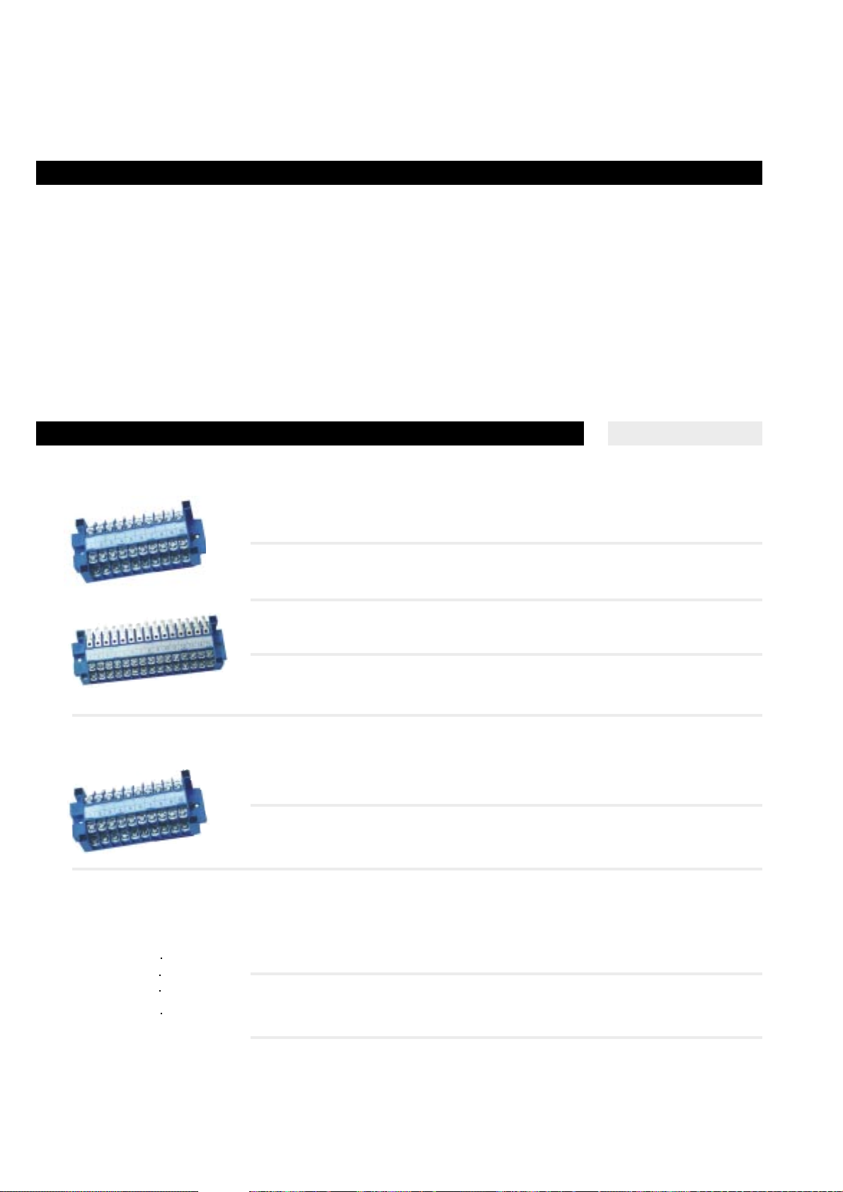
4.5 Screwtype Strips/Boxes
Quante
TM
Connection Strips
Specific Connectors
Description
Ref.-No.Type/Order text
Hole spacing: 96 mm
Total length: 106 mm
Connection strip 10 pairs SL/SL 75101-639 00
Material: ABS
PU: 5 pcs. Weight: 0.1 kg
Hole spacing: 170 mm Designation strips*
Total length: 179 mm a (insertable) b (screwed-on)
Connection strip SL/SL - 1 71101-636 00
Material: PC; PU: 20 pcs. Weight: 0.13 kg
Connection strip S/L 1 - 71101-632 00
Material: ABS; PU: 20 pcs. Weight: 0.125 kg
Wire guiding comb flat, one-sided 71111-003 00
Open on either side, for connection strip type A;
comb opening for conductors 0.6 mmØ
Material: Plastic PVC, grey; PU: 1 pce. Weight: 0.007 kg
Dimensions (L x W x D): 106 x 61 x 1.5 mm
Labelling strips for connection strip 71156-509 00
Plugged on connection strip type B
Material: ABS, grey; PU: 1 pce. Weight: 0.006 kg
Dimensions (L x W x D): 179 x 12 x 4 mm
Wire guiding comb flat, two-sided 71111-007 00
Open on both sides, for connection strip type B;
comb openings for conductors 0.6 mmØ
Material: Plastic PVC, grey; PU: 10 pcs. Weight: 0.16 kg
Dimensions (L x W x D):179 x 64 x 1.5 mm
Wire guiding comb flat, two-sided 71111-517 00
Open on either side for elevated mounting of connection strip type B;
comb opening for conductors 0.6 mmØ
Material: Plastic ABS, grey; PU: 10 pcs. Weight: 0.3 kg
Dimensions (L x W x D): 179 x 75 x 7.5 mm
For use in distribution boxes and distribution frames.
The following forms and types are available as standard:
Type A (short version)
20-pole / for 10 pairs + earth,
Type B (long version)
20 and 40-pole / for 10 and 20 pairs + earth.
Ascrew terminal is available for the system earth, however, tho connect several earth wires together an earth bus is recommended.
Each connection strip is equipped with a designation label for
marking,
To ensure that clear arrangement of the cable is achieved, wire
guide combs are available and can be attached to the strips.
Materials
Plastic base:
a) ABS (acrylic nitrile butadiene styrene)
b) Polycarbonate GV (macrolon GV)
Contact parts
CuZn (brass) 6 µm nickel-plated; soldering joints tinned;
terminal screw CuZn, nickel-plated.
Characteristics
Application class GSF according to DIN 40 040
(-40°C ... +70°C with relative humidity ≤ 75 %)
Leaking paths and air paths: ≥ 104 ohms;
Test voltage: 2 kV / 50 Hz / 1 min.
Technical data
Protection class: IP 20.
Rated voltage (VDE 0100 group C):
500 V ~ 600 V = Maximum Operating current: 8 A
Dielectric strength: 2.5 kVeff.
Temperature limit: -40°C ... +100°C.
Type of wire connection
incoming side outgoing side
combined connection SL SL combined connection
Page 17

Quante TRP, Quante B12P indoor screwtype boxes
4.5 Screwtype Strips/Boxes
Quante
TM
TRP, Quante
TM
B12P
Description
308
• The range can be extended as required to cover all needs
- box in enclosed version
- disconnection strip with looping facility
- all sizes from 5 in steps of 5 (5, 10, 15... up to 120 pairs)
- screw termination on one side and solder terminals on the other
- grey colour
• Cabling quality and convenience
- Products are approved by France Telecom and the French Navy
- Easy cabling due to the bracket on each screw
- A dark section inside the cover allows marking opposite the posts
• A complete range of screwtype distribution boxes for cable
systems within buildings.
• 12-post B12P boxes with connection of both wires to the same
post. Very easy to work. The terminal strip can be cabled out of
the box. Very economical and of a design similar to the female
telephone junction. The B12P box is the ideal product for subscriber distribution.
• 5 and 10 pair boxes. Essential for ultimate cabling, these two
boxes are equipped with a connection strip with through posts
which allow connection of the input wires on one side and the
output wires on the other side.
• 20 to 120 pair boxes. These boxes are very small, due to the twostage strip design, and they combine easy cabling with high density.
Dimensions in mm
HWD
B12P 75 75 35
TRP, 5 pairs 107,5 54 32
TRP, 10 pairs 184,5 54 32
TRP, 20 pairs 169 152,5 42,5
TRP, 30 pairs 169 152,5 42,5
TRP, 50 pairs 270 270 64,5
TRP, 60 pairs 270 270 64,5
TRP, 100 pairs 370 369 68
TRP, 120 pairs 370 369 68
Technical characteristics
Connection modules
Conductor diameter, max: 1.5 mm
Dielectric strength: 1500 V rms at 50 Hz
Insulation resistance at 500 V dc: > 10000 MΩ
Boxes
Protection ratio: IP 30 (EN 60 529)
Colour: Ivory to RAL 9001
Cover with captive screws or click-on
Page 18

For distribution of telephone cables in buildings or for any light-current cabling system.
Post-type boxes
(1 post= 1 wire)
12-post box NN3420580000
5 and 10 pair boxes
TRP, 5 pairs NN542330VA00
TRP, 10 pairs NN542332VA00
20 and 30 pair boxes
TRP, 20 pairs NN5423560000
TRP, 30 pairs NN5423570000
TRP, 50 pairs N421007A0000
TRP, 60 pairs N421008A0000
TRP, 100 pairs N421009A0000
TRP, 120 pairs N421010A0000
309
4
4.5 Screwtype Strips/Boxes
Quante
TM
TRP, Quante
TM
B12P
Ref.-No.Type/Order text
Specific Connectors
Page 19

Small distribution boxes for telecommunication installations, clock,
alarm systems, etc.
Made of plastic for indoor use, surface mounting type.
Protection class is IP 31 (EN 60529)
The boxes are made of thermoplastic synthetic material (ABS), with
high impact resistance, colour is RAL 7032, pebble-grey.
All metal parts are made of brass, nickel plated. Metal links with
tinned soldering tags (for test purposes) are located on either side
of the M3 x 6 terminal screws.
Knockout markings on all sides of the cover for cable inlet.
Standard equipment
3-pair version:
6 terminals, 1 earthing terminal, snap-on cover.
4-pair version:
8 terminals, 2 earthing terminals, screw-mounted cover.
Optional monitoring switch
6-pair version:
12 terminals, 2 earthing terminals, snap-on cover.
3-pair box
Ref.-No.Type/Order text
4.5 Screwtype Strips/Boxes
Quante
TM
Distribution Boxes 3-6 pair
Description
310
4-pair box
6-pair box
3-pair box 50-006-11000
PU: 1 pce. Weight: 0.05 kg
4-pair box 50-008-11100
PU: 1 pce. Weight: 0.08 kg
Accessory
Monitoring switch 50096-501 00
PU: 1 pce. Weight: 0.01 kg
6-pair box 50-012-11000
PU: 1pce. Weight: 0.09 kg
Page 20

Connection modules with screw or solder contacts, the DE and
DEC range of products are ideal for a wide range of connection
duties internally and externally.
• A simple range:
- DE module for connection
- DEC module with disconnection point for testing
- Two capacities (10 or 15 pairs)
• Compatible with all our supports:
- BDM external boxes
- RSP internal boxes
- MS distribution frames
• Easy to install and manage:
- Simple terminals (screw or solder)
- Compact design (contacts arrayed on two levels)
- Generously dimensioned insulation
- DEC modules have disconnection LED
- mounted on flat surfaces.
• Accessories:
- Insulating wire guide channel using the same mountings as
the module
- Special fixing nuts
311
4
4.5 Screwtype Strips/Boxes
Quante
TM
DE Screwtype
Specific Connectors
Description
Technical characteristics
Without wire guides
Length Widt Height Mounting
DE 10 pair 96.5 44 20.7 2 x ø 3 screws
DE 15 pair 132.5 44 20.7 2 x ø 3 screws
DEC 15 pair 96.5 44 28.2 2 x ø 3 screws
DEC 15 pair 132.5 44 28.2 2 x ø 3 screws
With wire guides
DE 10 pair 96.5 80 26.7 2 x ø 3 screws
DE 15 pair 132.5 80 26.7 2 x ø 3 screws
DEC 15 pair 96.5 80 34.2 2 x ø 3 screws
DEC 15 pair 132.5 80 34.2 2 x ø 3 screws
DE and DEC modules
Types
DE: connection only
DEC: connection and disconnection
Materials:
Contacts: copper alloys
Insulation: thermoplastic
Wire guides: thermoplastic
Connection
Conductor size: 1.2 mm max.
Types of connection
VVD: screw terminals on each side
VSD: screw terminals on one side, solder on the other
Connection to solder terminals
By soldering
By FASTON tab 2.86 mm or equivalent
Connection to screw terminals
Conductor clamped under projecting collar
Electrical characteristics
Dielectric strength: ≥ 1500 V at 50 Hz
Insulation resistance: ≥ 10000 MΩ at 500 V
Rated current: 10 A at 220 V
Dimensions in mm and mounting (screws not supplied)
Page 21
10 pair strip with wire guide NN1550230100
15 pair strip with wire guide NN1550240100
DIN asymmetrical rail, 32 mm NN1003140000
2 meters
Pack of 100 Fixocap M5 - M3 nuts NN1858350000
VVD 10 pair strip 237100000000
Screw/screw contact
VVD 15 pair strip 237101000000
Screw/screw contact
VSD 10 pair strip 237104000000
Screw/solder contact
VSD 15 pair strip 237105000000
Screw/solder contact
Ref.-No.Type/Order text
4.5 Screwtype Strips/Boxes
Quante
TM
DE Screwtype
312
The dimensions and mounting hole centres of the DE and DEC
modules are compatible with RSP and BDM boxes.
• Centres
- 10 pair module: 86.4 mm
- 15 pair module: 122.4 mm
• The module can also be mounted on frames in one of two ways
- They can be screwed to support arms of flats
- They can be screwed to the DIN asymmetrical rail
(with special Fixocap nuts)
• DEC disconnection
The DEC modules are supplied with centrally mounted
disconnection jumpers.
• Disconnection is performed in three stages
- Withdraw jumper
- Turn through 90°
- Replace jumper in socket (the jumper position is indicated
by a mark)
Description
Quante DE connection Strip
Quante DEC disconnection Strip
VVD 10 pair strip NN3360310000
Screw/screw contact
VVD 15 pair strip NN3360320000
Screw/screw contact
Accessories
Page 22

Box
Base and cover made up of light grey plastic
Protection ratio: IP 31
Sliding cover, fastened to base via a nylon cord.
Connecting device
2 pair module with screw-screw connection terminal
Maximum diameter of conductors: 1.5 mm
Electrical characteristics
Dielectric strength: 1000 V AC 50 Hz
Insulation resistance at 500 V > 10000 MW
Mounting
Wall-mounting: using 4 mm diameter screws (not supplied)
Pole-mounting: using 10 mm wide metal straps (not supplied)
313
4
4.5 Screwtype Strips/Boxes
Quante
TM
BR2
Specific Connectors
Description
Technical characteristics
Because of its reliability, the BR2 box is approved and used by PTT Administrations in France and in Pakistan.
Quante BR2 screwtype outdoor Box
The BR2 box is used for outdoor distribution of dropwires to subscriber.
BR2 box equipped NN4420760000
2 pair module NN3372450000
5 x 12
79,5
4
11
12
2 oblong holes
fixing
Ref.-No.Type/Order text
• Practical box
- easy operation,
- easy mounting, either on wall or pole.
• Ventilated set
• Nice and compact design
• Compact design
• Adaptability
- easy arrangement according to user’s needs.
 Loading...