

Page 1

3M Personal Safety Division
3MTM Sound Examiner SE-400 Series Sound Level Meters with Intrinsically Safe models
Sound Examiner
SE-400 Series Sound Level Meter
User Manual
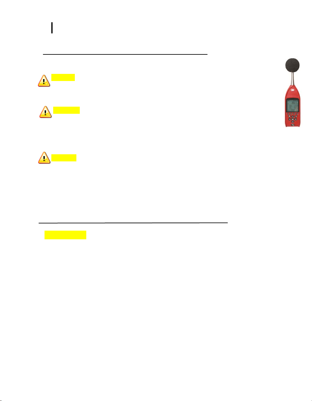
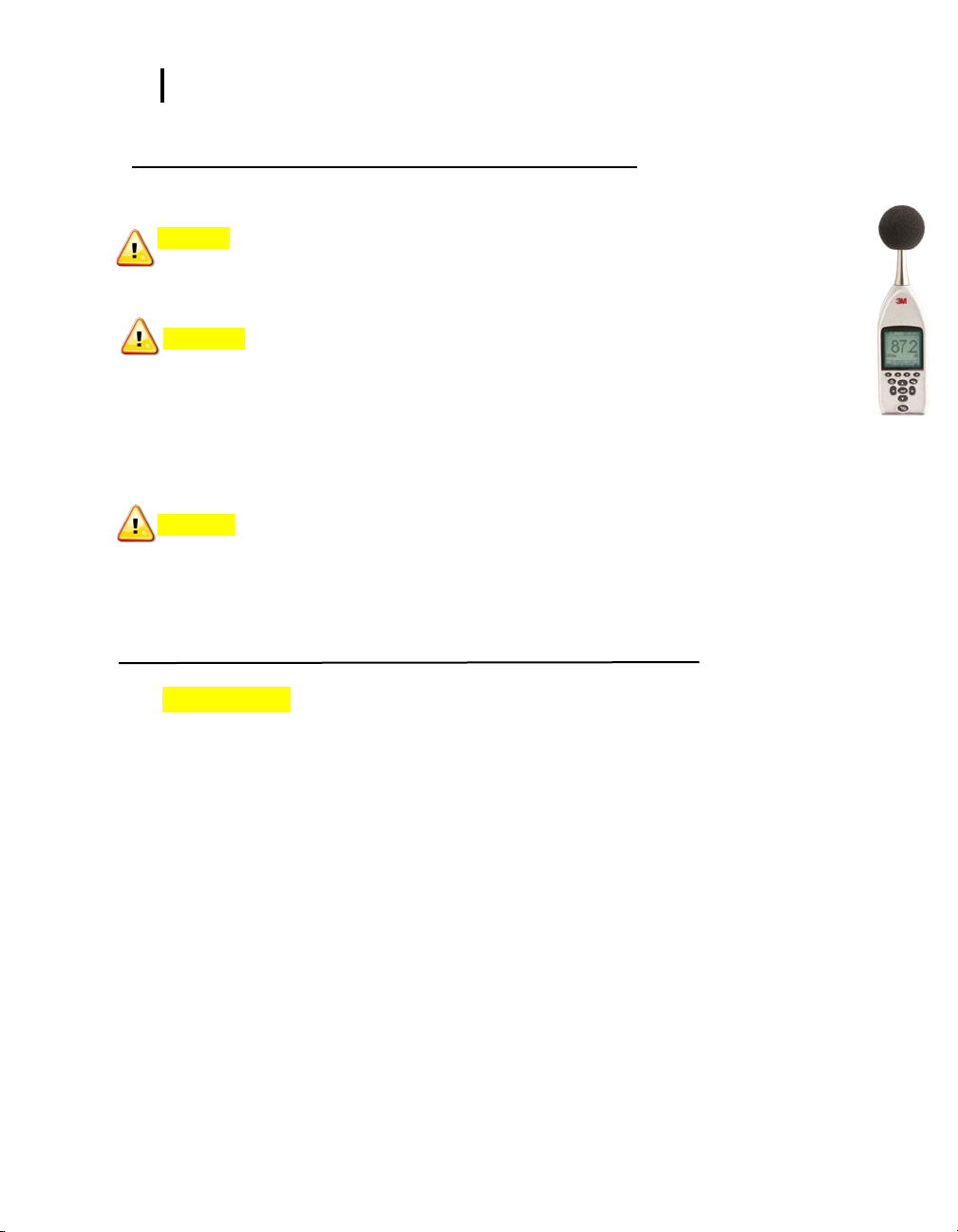
SE-401/SE-402
non-IS models
SE-401/SE-402
Intrinsically Safe models
Page 2
Dangers, Warnings, Cautions & Battery IS models
i
3MTM Sound Examiner SE-400 IS Series Sound Level Meter
Dangers, Warnings, Cautions & Battery
Danger!
Failure to observe the following procedures may result in serious personal injury
• Contains built-in lithium p olymer battery. D o not incinerate or dispose of in fire. Do not disassemble, alter, or re-construct.
• This product must not be charged in hazardo us locations.
Warning!
Failure to observe the following procedures could damage the instrument
• Read the manual before operat ion.
• Do not store in temperatures outside -20°C to 60°C (-13°F 140°F).
• Do not immers e in liquids.
• Condensation may damage yo ur instrument.
+
Caution!
General
• Substituti on of components may impair the accuracy of the i nstrument. Rep air should be performed by aut horized service
personnel only.
• The battery in this instrument has limited shelf-life, even i f never used.
• A non-condensing envi ronment is required for proper m easurements.
• Do not charg e battery outsid e the range of 0°C to 40 °C (32°F to 104°F).
• Battery run-time may be reduced when operating at lower than 0°C (32°F) temperatures.
• Contains Lithium Cell 4.2V/1500 mAH do not at tempt to replace in a hazardo us location.
Intended Use:
The SE-400 Series IS models are intended to measure sound pressure levels in air and may measure in certain hazardous
locations as identified by the User Warnings, Safety Markings, and Standard information page iii, part number: 053-777.
Consult your company’s safety professional for local standards, or call 3M at 1-800-243-4630.
073-300 RevA
Page 3
Dangers, Warnings, Cautions & Battery non-IS models
ii
3MTM Sound Examiner SE-400 non-IS Models Sound Level Meter
Dangers, Warnings, Cautions & Battery
Danger!
Failure to observe the following procedures may result in serious personal injury
• Not for use in explosive or haz ardous locations. This product is not intri nsically safe.
• Contains built-in lithium p olymer battery. D o not incinerate or dispose of i n fire. Do not disas semble, alter, or re-construct.
Warning!
Failure to observe the following procedures could damage the instrument
• Read the manual befor e operation.
• Do not store in temperatures outside -20°C to 60°C (-13°F 140°F).
• Do not immers e in liquids.
• Condensation may damage yo ur instrument.
• Substituti on of components may impair the accuracy of the i nstrument. Rep air should be performed by aut horized service
Caution!
General
personnel only.
• The battery in this instrument has limited shelf-life, even i f never used.
• A non-condensing envi ronment is required for proper m easurements.
• Do not charg e battery outsid e the range of 0°C to 40°C (32°F to 104°F).
• Battery run-time may be reduc ed when operati ng at lower than 0°C (32°F) temperatures.
Intended Use:
The SE-400 Series non-IS models are intended to measure sound pressure levels in air. Consult your company’s safety
professional for local standards, or call 3M at 1-800-243-4630.
Page 4
Sound Examiner Intrinsically Safe Models: user warnings, safety marki ngs, and standar d information
iii
Manufacturer
3M Company
Equipment/model
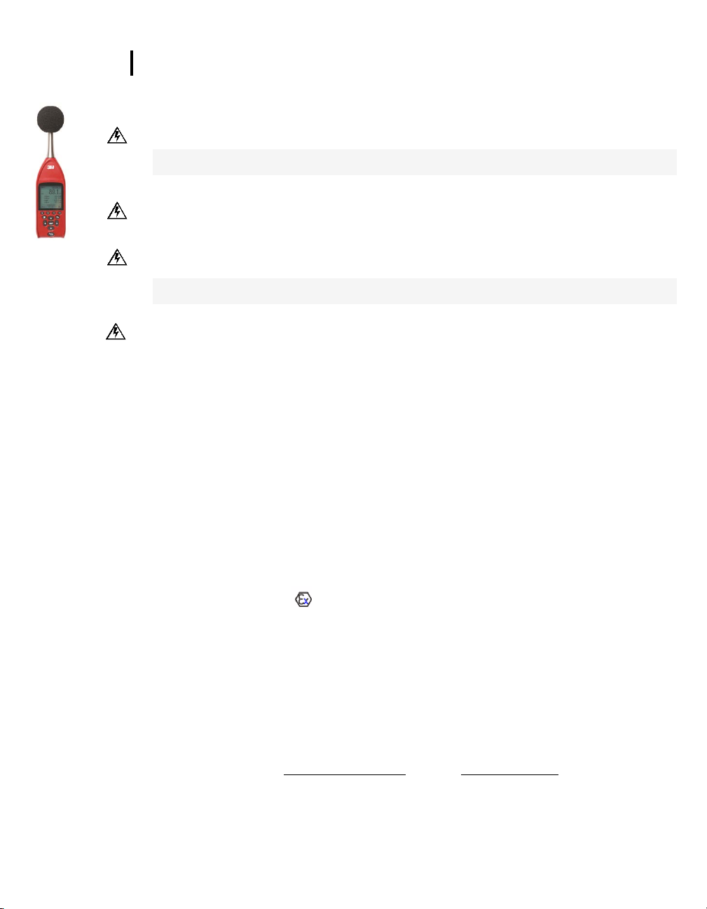
SE-401 Intrinsically Safe Cl ass1/Type 1 model
Hazardous Locat i on s Cl as s
II 1 G Ex ia IIB T4 (DEMKO 13 ATEX 1210031X)
Certificat e number
IECEx UL 13.0006X, Class I, Division 1, Groups C a nd D;
Exi is define d as Intrinsically Safe and Sécruité Intrinsèque
Maximum charge input voltage
Um=5.5V
Maximum inp u t current
Ii = 500ma
Sound Examiner SE-401 and SE-402 Intrinsically Safe/Sécurité Intrinsèque Models: user warnings, safety markings, and standards information
Safety Standards
• CE mark
• UL 913, Ed.7, 2011-09-23: Standard for Intrinsicall y Safe Apparatus and Associate d Apparatus for Use in Class I, II, III, Division 1,
• CSA C22.2 No. 157-92, (R2013): Intrinsically Safe and Non-I ncendive Equipment for Use in Hazardous Locations
• EN 60079-0 (2009): Explosive atmospheres . Equipment. Ge neral requirements
• EN 60079-11 (2012): Explosive atmospheres – Part 11: Equipment protection by intri nsic safety
• EN 60079-26 (2007): Explosive atmospheres – Part 26: : Equipment with equi pment protection level (EPL) Ga
• IEC 60079-0 Ed.5 (2007): Explosive atmospheres - Part 0: Equipment - General requi rements
• IEC 60079-11 Ed. 6: (2012): Ex plosive atmosp heres - Part 11: Equipment prot ection by intrinsic safety
• IEC 60079-26 Ed. 2: (2009): Expl osive atmospheres - Part 26: Eq uipment with eq uipment protection level (EPL) Ga
Safety Markings
WARNING: To prevent ignition of flammable or co mbus t ibl e atm os ph eres , there are no serviceable parts. Repair and battery
replacement must be done by authorized service personnel only.
Avertissement: Pour évit er l'inflammati on d'atmosphères inflammables ou combusti bles, il n'y a pas de pièces réparables.
Réparation et remplacement de la batterie doivent être effectués par le personnel de s ervice autorisé.
WARNING: Substitution of comp onents may impair intrinsic safety. Do not open.
Avertissement: La substitut ion de composants peut compromettre la Séc urité Intrinsèque.
WARNING: Contains built-in li thium polymer battery. Do not incinerate or dispose of in fire. Do not disassemble, alter, or re-
construct.
Avertissement: Contient l a batt erie intégrée au lithium polymère. Ne pas incinér er ou jeter au feu. Ne pas dém ont er , modifier
ou re-construire.
WARNING: To reduce the risk of explosion, rec harge the battery outside of the hazardous locations.
Avertissement: Afin de prévenir l’inflammation d’atmosphères dangereuses, ne changer les batteri es que dans des
emplacement s désignés non dangereux.
SE-401 IS model and SE-402 IS model
0539 ,
Hazardous (C lassified) Loc ations
3M Authorized Service
• Contact 3M
1060 Corporate Ce nt er Drive
Oconomowoc, WI 53066
Contact: 1-800-245-0779 or email: 3Mdetectionmail@mmm.com
See User Manual for additional details.
(Part number: 053-777 RevB; 11/13)
073-300 RevA
SE-402 Intrinsically Safe Cl ass 2/Type 2 model
Ambient tem perature range: -20ºC to +50ºC
or Internet: www.3m.com/detection
Page 5

ii Table of Contents
TABLE OF CONTENTS
Introduction ............................................................................................................................................................................................................... 1
Models and options ............................................................................................................................................................................................... 1
Sound Examiner SE-400 Series o verview .............................................................................................................................................................. 1
Display and keypad ............................................................................................................................................................................................... 1
Diagram and funct i onal it y ...................................................................................................................................................................................... 2
Screen components identified ............................................................................................................................................................................... 2
Connectors/Ports ...................................................................................................................................................................................................... 3
USB........................................................................................................................................................................................................................ 3
M
Detectio n Management Software (DMS) ...................................................................................................................................................... 3
3MT
Getting Started .......................................................................................................................................................................................................... 4
Checking the equipment ........................................................................................................................................................................................ 4
Turning on.................................................................................................................................................................................................................. 5
Softkeys ................................................................................................................................................................................................................. 5
Screen indicators ................................................................................................................................................................................................... 5
Measurement/Start screen ....................................................................................................................................................................................... 6
Navigating .............................................................................................................................................................................................................. 6
Turning off ................................................................................................................................................................................................................. 6
Charging ................................................................................................................................................................................................................ 7
Charging states ..................................................................................................................................................................................................... 7
Setup/instrument configuration .............................................................................................................................................................................. 8
Response tim e and frequency weighting settings ................................................................................................................................................. 8
Opening the s etup screen for i nstrument configuration ........................................................................................................................................ 9
Meter settings ...................................................................................................................................................................................................... 10
SE-400 Series information details ....................................................................................................................................................................... 11
Time and date setting .......................................................................................................................................................................................... 12
Security: l ocking and unlocking run/setup .......................................................................................................................................................... 14
Memory and spac e .................................................................................................................................................................................................. 15
Deleting files and viewing memory ...................................................................................................................................................................... 15
Resetting the SE-400 Series .................................................................................................................................................................................. 15
Calibrate, measure, run, a nd saved results ......................................................................................................................................................... 16
Overview of running a session ............................................................................................................................................................................ 16
Sound Examiner SE-400 Series
Page 6

iii Table of Contents
Calibrate ................................................................................................................................................................................................................... 16
Performing a Calibration ...................................................................................................................................................................................... 16
Measure .................................................................................................................................................................................................................... 19
Logged Data ........................................................................................................................................................................................................ 19
Windscreen .......................................................................................................................................................................................................... 19
Positioning and tripod mount ............................................................................................................................................................................... 20
Measurements and displayed parameters .......................................................................................................................................................... 20
Run, stop, and view results ................................................................................................................................................................................. 21
Download and vie w log g ed dat a ........................................................................................................................................................................... 22
DMS & downloaded measurements .................................................................................................................................................................... 23
SoundPatrol feature ................................................................................................................................................................................................ 25
Connecting the printer and settings .................................................................................................................................................................... 25
Printing and reports ............................................................................................................................................................................................. 27
Microphone pr e amp ................................................................................................................................................................................................ 28
Attaching the preamp .......................................................................................................................................................................................... 28
Connecting an ext ens i on ca ble ........................................................................................................................................................................... 28
Standards/Directives .............................................................................................................................................................................................. 30
Acoustical C haracteristics ..................................................................................................................................................................................... 30
Microphones ........................................................................................................................................................................................................ 30
Measurements ......................................................................................................................................................................................................... 31
Calibration ............................................................................................................................................................................................................ 31
Mechanical Ch ar act er ist ic s .................................................................................................................................................................................... 31
Physical Characteristics ...................................................................................................................................................................................... 31
Environment al C har a cter i sti c s .............................................................................................................................................................................. 31
User Interface Ch ar a cter ist i cs ............................................................................................................................................................................... 32
Power/Elect rical Characteristics ........................................................................................................................................................................... 32
Ports and connect io n s ........................................................................................................................................................................................... 32
SE-400 Series models and part numbers ............................................................................................................................................................. 33
Accessories (sold separately) ............................................................................................................................................................................. 33
Glossary of Term s ................................................................................................................................................................................................... 34
Customer service .................................................................................................................................................................................................... 39
Contacting 3M Instrument ation ........................................................................................................................................................................... 39
Internatio nal customers ....................................................................................................................................................................................... 39
Sound Examiner SE-400 Series
Page 7

iv Table of Contents
Calibration ............................................................................................................................................................................................................... 39
Warranty ................................................................................................................................................................................................................... 39
Data Addendum: SE-400 Series measuring to IEC 61672-1 .............................................................................................................................. 40
Figures:
Figure 1-1: SE-400 Screen components ................................................................................................................................................................... 2
Figure 1-2: Co nnector and por ts ................................................................................................................................................................................ 3
Figure 1-3: Ac oustic data and DMS charting example ............................................................................................................................................. 3
Figure 2-1: Identify SE-400 Series equip me nt ........................................................................................................................................................... 4
Figure 2-2: Me asurement scr een ................................................................................................................................................................................ 6
Figure 2-3: Ch arging state ......................................................................................................................................................................................... 7
Figure 3-1: Response time and frequency weighting ................................................................................................................................................ 8
Figure 3-2: Op ening the Setup s creen....................................................................................................................................................................... 9
Figure 3-3: Ch oosing meter settings ........................................................................................................................................................................ 10
Figure 3-4: Ch oosing meter settings ........................................................................................................................................................................ 10
Figure 3-5: Unit Information screen ......................................................................................................................................................................... 11
Figure 3-6: Time and Date Setu p screen ................................................................................................................................................................ 12
Figure 3-7: Auto-Run screen .................................................................................................................................................................................... 13
Figure 3-8: Auto-Run screen .................................................................................................................................................................................... 13
Figure 3-9: Secure run and measurement sc reen ................................................................................................................................................... 14
Figure 3-10: D eleting sessions/files and v iewing memory ...................................................................................................................................... 15
Figure 4-1: SE-400 Series and calibr ating ............................................................................................................................................................... 17
Figure 4-2: Calibration soft key selection ................................................................................................................................................................. 17
Figure 4-3: Calibration screen.................................................................................................................................................................................. 18
Figure 4-4: CAL screen ............................................................................................................................................................................................ 18
Figure 4-5: Ex ample of logged data in DMS ............................................................................................................................................................ 19
Figure 4-6: SE-400 Series with windscreen ............................................................................................................................................................ 19
Figure 4-7: Me asurement posi tioning and tripod mount .......................................................................................................................................... 20
Figure 4-8: Main/multi- measurement screen in Run mode .................................................................................................................................... 21
Figure 4-9: Single measurement screen in st op mode ............................................................................................................................................ 21
Figure 4-10: S es s ion di r ect ory sc reen ..................................................................................................................................................................... 22
Figure 4-11: S aved sessions ................................................................................................................................................................................... 22
Figure 4-12: R eviewing Session Data ..................................................................................................................................................................... 23
Figure 4-13: S ample Sound Exam iner data report .................................................................................................................................................. 23
Figure 4-14: D ownloading files from DMS to SE-400 Series .................................................................................................................................. 24
Figure 4-15: B aud rate setup a nd print icon ............................................................................................................................................................ 25
Figure 4-16: Print Setup screen ............................................................................................................................................................................... 26
Figure 4-17: Example of extension cable and preamp ............................................................................................................................................ 28
Figure 4-18: S E -400 Series wit h extension cable and preamp att achment ............................................................................................................ 28
Tables:
Table 1-1: Sound Ex ami ner SE-400 models explained ............................................................................................................................................. 1
Table 1-2: Keypad keys identified ............................................................................................................................................................................... 2
Table 2-1: Softkeys explained..................................................................................................................................................................................... 5
Table 3-1: Meter settings explained ......................................................................................................................................................................... 11
Sound Examiner SE-400 Series
Page 8

1 Introduction
Models/Series
SE-402 IS
* * *
SE-401 IS
* * *
* * * *
* * *
SE-402R Non-IS
* *
* * * *
Models and options
Introduction
The 3MTM Sound Examiner SE-400 Series are sound level meters used to measure noise over time with robust
logging capabilities, selective measurement values, and with a variety of end-user applications including
occupational noise measurements and assessment of environmental noise levels.
Models and options
There are five models offered in the Sound Examiner Series including intrinsically safe (IS) and non-intrinsically safe
models. The differences between models are accounted for by three primary characteristics: intrinsic safety,
accuracy of measurement, and remote microphone measurement capability. The table below summarizes the
differences between the models.
CHAPTER
1
preamp
Serial printing
External outputs: AC/DC
Remote cap ability with removable
(SoundPatrol add-on option)
USB connectivity
Removable Pre am p
Sound Examiner
SE-401 Non-IS
SE-402 Non-IS
Class/Type 1
Intrinsically safe
Class/Type 2
*
*
Table 1-1: Sound Examiner SE-400 IS and non-IS models explained
Sound Examiner SE-400 Series overview
Display and keypad
The keypad is used to run and stop your sessions, view your measurement values, select specific set up
parameters, and power on and off the sound level meter.
Sound Examiner SE-400 Series
Page 9

2 Sound Examiner SE-400 Series overview
Keypad Description
1. Softkeys
There are four softkeys which are used as
2. Backlight key
Used to illuminate the background of the display
session.)
3. Up Arrow key
Used to toggle through menu/setup options and
screen.
4. Left Arrow key
Used to navigate through menus and setup
parameters.
5. Run/Stop key
Used to run and stop a logged session.
6. Right Arrow key
Used to navigate through menus and setup
7. Enter key
Used to select menus and confirm setup parameter
8. Down Arrow key
Used to toggle through menu/setup options and
9. On/Off/Esc key
Used to power on, power off and/or escape or
Screen indicators
1
2
3
4
The SE-400 Series has four screen components identified below.
Diagram and functionality
Diagram and functionality
The following diagram for SE-400 series explains the features on the keypad and the display’s screen
indicators.
additional menu options when working with specific
screens (e.g., measurement screen).
screen. (i.e., low lighting environment, nighttime
scrolls through the values on the measurement
parameters.
changes.
5
6
7
8
9
scrolls through the values on the measurement
screen.
move back one screen.
Table 1-2: Keypad keys identified
Screen components identified
Figure 1-1: SE-400 Series Screen components
Main screen
Time & Date/error messages
Softkey menus
A: Settings, B: Fast/Slow Time Response
C: A, C, or Z Frequency Weighting
D: SoundPatrol feature provides printing capability (non-IS models only)
Sound Examiner SE-400 Series
Page 10

3 Connectors/Ports
USB connector
AC/DC output
model only.)
I/O and serial
USB
Connectors/Ports
The Hardware connector ports are identified below. Note: the SE-400 IS models are equipped with USB
connector only.
(SE-400 non-IS
printing connector
(SE-400 non-IS
model only.)
Figure 1-2: Connector and ports
USB
A USB cable is shipped with each Sound Examiner. One end fits the mini port in the instrument. The
other end fits a standard USB connector on a personal computer.
A USB connection to a computer allows files to be transferred, settings to be downloaded to the
instrument, and post-session analysis to be performed with the DMS software. It is also used to charge
the internal battery of the SE-400 Series.
3MTM Detection Management Software (DMS)
DMS is a software application from 3M that is used for a variety of Sound Examiner functions including
the ability to display and manipulate data after it is downloaded to the computer from the instrument.
Additionally, DMS is used to download measurement data for advanced graphing, charting, and reporting
analysis.
Figure 1-3: Acoustic data and DMS charting example
for charging
Sound Examiner SE-400 Series
Page 11

4 Getting Started
SE-400 IS model
Removable Preamp
model SE-402R)
Windscreen
USB cable
DMS software
SE-400 Series
Microphone
AcoustiCal with adapter
SE-400 non-IS
Checking the equipment
Getting Started
This chapter provides the basic information you need to “get up and go” essentially right out of the box,
including receiving your first glimpses of sound pressure level (SPL).
Checking the equipment
If your instrument was sent in a storage case, you will want to remove the packaging and acquaint
yourself with the equipment, so you can quickly get started. The items below are included in a “standard”
Sound Examiner SE-400 Series kit with a calibrator.
USB powe r cord
with universal
plug adapters
• Optional feature
Figure 2-1: Identify SE-400 Series equipment
CHAPTER
2
(when equipped on
User Manual
Sound Examiner SE-400 Series
 Loading...