

Page 1
3
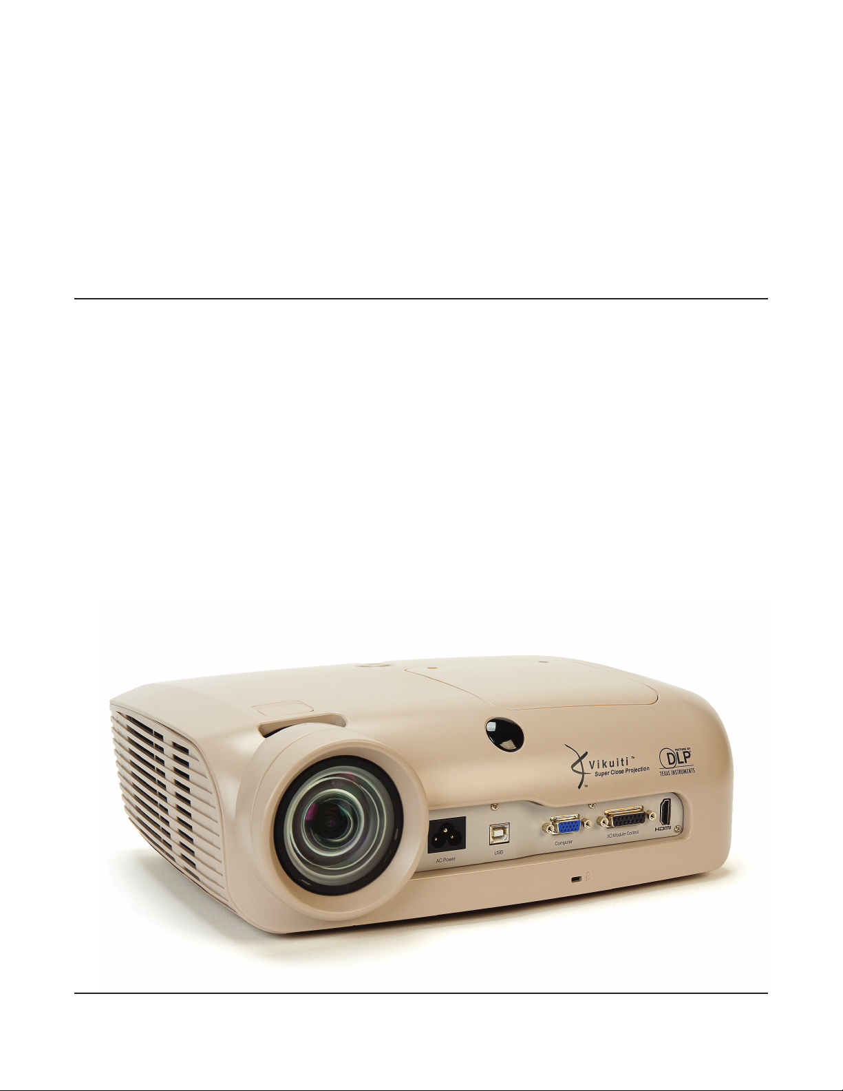
Super Close Projection System
SCP725
Operator’s Guide
April 2012 • 78-6971-1572-9 • Copyright © 2011, 3M Company. All Rights Reserved.
Page 2

Page 3

™
Super Close Projection System SCP725
3M
Contents
Operator’s Guide
Introduction
Thank You for Choosing 3M Equipment ......................................................................................................5
Trademarks ....................................................................................................................................................5
Important Notice ............................................................................................................................................5
Warranty; Limited Remedy; Limited Liability ..............................................................................................5
Product Patents ..............................................................................................................................................7
Regulatory Notices ........................................................................................................................................7
Safety Information
Intended Use ..................................................................................................................................................9
Safety Labels ...............................................................................................................................................12
Contents of Shipping Box
Keep Your Packing Materials ......................................................................................................................13
What’s Next? ...............................................................................................................................................13
Product Description
Machine Characteristics ...............................................................................................................................14
Dimensions ..................................................................................................................................................14
Projector Distance from Screen and Image Size .........................................................................................15
Vertical Lens Shift .......................................................................................................................................15
Parts Identification .......................................................................................................................................16
Projector Terminal Connections ..................................................................................................................16
I/O Module Control Panel (optional accessory) ..........................................................................................17
Top Terminal Panel on I/O Module .............................................................................................................17
Bottom Terminal Panel on I/O Module .......................................................................................................18
Remote Control Functions ...........................................................................................................................19
Installing Batteries in Remote Control ........................................................................................................ 20
Setup and System Configuration ................................................................................................................. 20
ENGLISH
Operating Instructions
Projector Start Up ........................................................................................................................................21
Stand By Mode ............................................................................................................................................21
© 3M 2011. All Rights Reserved.
3
Page 4

Operator’s Guide
Menu Navigation
Main Menu ...................................................................................................................................................22
Input Menu ...................................................................................................................................................23
Picture Menu ................................................................................................................................................24
Advanced Picture Menu ..............................................................................................................................25
Audio Menu .................................................................................................................................................26
ENGLISH
Setup Menu ..................................................................................................................................................27
Advanced Setup Menu .................................................................................................................................28
Information Menu ........................................................................................................................................29
Machine Specifications
Maintenance
Lamp Replacement ......................................................................................................................................31
Cleaning the Air Vents .................................................................................................................................32
Cleaning the Lamp Module and Lamp Compartment .................................................................................33
Troubleshooting
Identifying an Expired Lamp Module .........................................................................................................35
I/O Module Troubleshooting .......................................................................................................................36
Projector Troubleshooting ...........................................................................................................................36
Projector Indicator Lights ............................................................................................................................39
I/O Module Indicator Lights ........................................................................................................................39
3M™ Super Close Projection System SCP725
Replacement Parts and Accessories
Replacement Parts .......................................................................................................................................40
Optional Accessories (not shown) ...............................................................................................................40
4
© 3M 2011. All Rights Reserved.
Page 5

™
Super Close Projection System SCP725
3M
Introduction
Operator’s Guide
Thank You for Choosing 3M Equipment
This product has been produced in accordance with 3M’s quality and safety standards to provide smooth and
trouble free use in the years to come. For optimum performance, please follow the operating instructions
carefully. We hope you will enjoy using this high performance product in your classroom, meetings,
presentations, and training sessions. This product is Class A and can not be sold into the home market.
Trademarks
The 3M logo and 3M are registered trademarks of 3M Company. Vikuiti is a trademark of 3M Company. Digital
Light Processing is a trademark or registered trademark of Texas Instruments. All other trademarks or registered
trademarks are property of their respective companies. HDMI, the HDMI Logo and High-Definition Multimedia
Interface are trademarks or registered trademarks of HDMI Licensing LLC.
Important Notice
All statements, technical information, and recommendations related to 3M’s products are based on information
believed to be reliable, but the accuracy or completeness is not guaranteed. Before using this product, you
must evaluate it and determine if it is suitable for your intended application. You assume all risks and liability
associated with such use. Any statements related to the product which are not contained in 3M’s current
publications, or any contrary statements contained on your purchase order shall have no force or effect unless
expressly set forth in a written agreement signed by an authorized officer of 3M.
Warranty; Limited Remedy; Limited Liability
ENGLISH
This warranty applies to the continental US only. The warranty terms, conditions, remedy and limitation may
vary in other countries. Contact your local 3M Company for warranty information.
The 3M SCP700 Series projector (the “3M Product”) is warranted to be free from defects in material or
manufacture for a period of three (3) years from the date of purchase or 4,000 hours of usage, whichever
occurs first.
All other accessories of the 3M Product (those in the applicable modular configurations), excluding the projector
lamps, but including the wall mounts, ceiling mounts, digital annotation sensors, and input/output devices
are warranted to be free from defects in material or manufacture for a period of one (1) year from the date
of purchase.
The lamp component of the 3M Product is warranted to be free from defects in material and manufacture for a
period of ninety (90) days after the date of purchase of the 3M Product or 180 hours of lamp usage, whichever
occurs first. This warranty is for parts only and in the case of an approved warranty claim for a lamp; your
exclusive remedy will be for a replacement product shipped to your location.
Optional product upgrades and/or accessories that are not sold as part of any modular configuration are subject to
individual warranties.
THE WARRANTIES STATED ABOVE ARE EXCLUSIVE AND ARE MADE IN PLACE OF ANY AND
ALL WARRANTIES, EXPRESS OR IMPLIED WARRANTIES OR CONDITIONS, INCLUDING ANY
IMPLIED WARRANTY OF MERCHANTABILITY OR FITNESS FOR A PARTICULAR PURPOSE, OR ANY
INDUSTRY PRACTICE OR CUSTOM OR TRADE USAGE.
In the event the 3M Product fails to conform to the above stated warranties within the applicable warranty
period, your exclusive remedy shall be, at 3M’s option, to replace or repair the 3M Product or to refund the
purchase price of the 3M Product. All replaced parts or products become property of 3M. If the product is
repaired, 3M will repair the defective part(s) with a new or used part(s). If the 3M Product is replaced, 3M
will replace the 3M Product with the same or equivalent model and with a new or refurbished 3M Product. In
the case of an approved warranty claim, the replacement 3M Product will carry only the remaining term of the
© 3M 2011. All Rights Reserved.
5
Page 6
Operator’s Guide
original 3M Product’s warranty period as stated above. For warranty service, you must provide proof of the
date of the original purchase else the manufacturing code date will be used to establish the start date of
the warranty. The following are exclusions to the above listed warranty:
a. This warranty does not cover 3M Product that is modified or damaged through improper storage, misuse,
abuse, accident, vandalism, improper installation, neglect, improper shipping, damage caused by acts of war,
disasters such as fire, flood, and lightning, improper electrical current, software problems, interaction with
non-3M products, or service other than by a 3M Authorized Service Provider, neglect or mishandling by any
ENGLISH
person. Normal wear and tear is not covered under warranty.
b. 3M Product is designed to operate in the typical indoor environment. This warranty does not cover 3M
Product used outside of the following circumstances:
•100V-240VAC,50/60Hz
•Office(orsimilar)Environmentswithlowlevelsofsmokeorairbornparticulates.
Altitude Temperature Humidity
0-4000 ft (normal fan speed) 5°C - 35°C (41°F - 95°F) 25% to 80%
4000-6000 ft (high fan speed) 5°C - 35°C (41°F - 95°F)
•Storageconditions:-20°Cto60°C,maximum40,000ft.
3M™ Super Close Projection System SCP725
(non-condensing)
c. The Air Intake and Exhaust Vent must be clear of obstructions, including any potential blockage or
obstructions caused from a ceiling or other mount. Inadequate air ventilation will cause the 3M Product to
malfunction or will cause damage to the 3M Product which will void the warranty.
d. This warranty does not cover any additional costs including, but not limited to, those associated with
removal, cleaning or installation of the 3M Product, adjustments, (mechanical or electronic) made to the 3M
Product or replacing customer replaceable parts like lamps and air filters.
e. This warranty covers only normal use of the product. 24-hour-per-day or other excessive continual use
causes strain and is not considered normal use.
f. This warranty does not cover consumables (e.g., fuses), other than lamps and only as set forth below.
g. This warranty is not transferable.
h. 3M is not responsible for warranty service should the 3M label or logo or the rating label or serial number be
removed unless otherwise stated in writing for the purpose of private labeling for partnership requirements.
i. This warranty does not cover postage, insurance, or shipping costs incurred in presenting your 3M Product
for warranty service. Said costs are the customer’s responsibility. If a claimed defect cannot be identified or
reproduced in service, the customer may be held responsible for cost incurred. Should your warranty upgrade
include a “change out” service and the claimed defect cannot be identified or reproduced by the technician,
the customer will be responsible for call out costs.
FAILURE TO FOLLOW THE INSTRUCTIONS CONTAINED IN THE APPROPRIATE 3M PRODUCT
MANUAL OR FAILURE TO USE THE 3M PRODUCT IN ACCORDANCE WITH 3M’S INTENDED
USE STATEMENT, WILL VOID ALL WARRANTIES AND LIMITED REMEDIES.
EXCEPT AS SPECIFICALLY STATED IN THE APPLICABLE 3M PRODUCT MANUAL, 3M SHALL
NOT BE LIABLE FOR ANY INDIRECT, INCIDENTAL, SPECIAL OR CONSEQUENTIAL DAMAGES
(INCLUDING, BUT NOT LIMITED TO, LOSS OF PROFITS, REVENUE OR BUSINESS) RESULTING
FROM, OR IN ANY WAY RELATED TO PERFORMANCE, USE OR INABILITY TO USE ANY OF THE 3M
PRODUCT. This limitation applies regardless of the legal theory upon which damages are sought.
For warranty support, please call or write your local 3M office or a 3M Authorized Service Provider to obtain
RMA # (Return Material Authorization Number) before returning the product. If you are inside the Continental
United States of America, please contact 3M Customer Service at 800-328-1371 or email meetings@mmm.com.
6
© 3M 2011. All Rights Reserved.
Page 7

™
Super Close Projection System SCP725
3M
Operator’s Guide
What 3M Will Do To Correct Problems:
•Ifyour3MProductrequiresservice,3Mwillaskyoutobringorsendthe3MProduct,securelypackagedinits
original container or equivalent, along with proof of the date of original purchase, to your 3M Service Dealer or
3M Service Center.
•3Mwill,atitsoption,repairorreplacethedefectiveunitwithoutchargeforpartsorlabor.Returnofthe
3M Product will be at 3M’s expense.
•Whenwarrantyserviceinvolvestheexchangeofthe3MProductorofapart,theitemreplacedbecomes
3M property.
•Theexchanged3MProductorpartmaybeneworpreviouslyrefurbishedtothe3Mstandardofquality,andat
3M’s option, the replacement may be another model of like kind and quality.
•3M’sliabilityforreplacementofthewarranted3MProductorpartwillnotexceedtheoriginalretailselling
price of the 3M Product. Exchange or replacement products or parts assume the remaining warranty period
of the product covered by this limited warranty. However, each replacement lamp carries the limited 90-day
warranty stated above.
Product Patents
This product is covered by one or more of the following patents:
U.S. Patent Number D555,184
U.S. Patent Number 7,123,426
U.S. Patent Number 7,126,767
U.S. Patent Number 7,271,964
ENGLISH
Regulatory Notices
Video signal cables: Only use cables delivered by the manufacturer.
FCC STATEMENT - CLASS A: This device complies with Part 15 of the FCC Rules. Operation is subject to
the following two conditions:
(1) this device may not cause harmful interference, and
(2) this device must accept any interference received, including interference that may cause undesired operation.
Instructions to Users: This equipment has been tested and found to comply with the limits for a Class A digital
device, pursuant to Part 15 of the FCC Rules. These limits are designed to provide a reasonable protection
against harmful interference when the equipment is operated in a commercial environment. This equipment
generates, uses, and can radiate radio frequency energy and, if not installed and used in accordance with the
instruction manual, may cause harmful interference to radio communications.
Operation of this equipment in a residential area is likely to cause harmful interference in which case the user
will be required to correct the interference at his own expense.
Notice: This Class A digital apparatus meets all requirements of the Canadian Interference-Causing Equipment
Regulations.
Cet appareil numérique de la classe A respecte toutes les exigences du Règlement sur le materiel brouilleur du
Canada.
Instructions to Users: This equipment complies with the requirements of FCC equipment provided that the
following conditions are met. The cables may have to be used with the core set to the projector side. Use the
cables which are included with the projector or specified.
Note: Changes or modifications not expressly approved by the party responsible for compliance could void the
user’s authority to operate the equipment.
© 3M 2011. All Rights Reserved.
7
Page 8

Operator’s Guide
3M™ Super Close Projection System SCP725
CE STATEMENT
Electromagnetic Compatibility Statement: Meets 2004/108/EC Directive
Low Voltage Directive: Meets 2006-95-EC Directive.
WEEE STATEMENT: The following information is only for EU-members States: The mark shown
to the right is in compliance with Waste Electrical and Electronic Equipment Directive 2002/96/EC
(WEEE). The mark indicates the requirement NOT to dispose the equipment as unsorted municipal
waste, but use the return and collection systems according to local law.
ENGLISH
RoHS STATEMENT: 3M Projection Systems can provide RoHS certification for products meeting the
RoHS directive.
1
European (EU) Restriction of Hazardous Substances (RoHS) Directive, 2002/95/EC.
1
RoHS compliant means that the product or part does not contain any of the substances in excess of the
following maximum concentration values in any homogeneous material, unless the substance is in an application
that is exempt under RoHS, as amended:(a) 0.1% (by weight) for lead, mercury, hexavalent chromium,
polybrominated biphenyls or polybrominated diphenyl ethers; or (b) 0.01% (by weight) for cadmium. This
information represents 3M’s knowledge and belief, which may be based on information provided by third party
suppliers to 3M.
8
© 3M 2011. All Rights Reserved.
Page 9
™
Super Close Projection System SCP725
3M
Safety Information
Operator’s Guide
Please read, understand, and follow all safety information contained in these instructions prior to the use of this
projector. Retain these instructions for future reference.
Intended Use
Before operating the machine, please read the entire manual thoroughly. This product was designed, built and
tested for use indoors, using 3M lamps and hardware. The use of other replacement lamps, outdoor operation or
different voltages has not been tested and could damage the projector or peripheral equipment and/or create a
potentially unsafe operating condition.
This projector is designed to operate in a normal office/classroom environment.
Altitude Temperature Humidity
0-4000 ft (normal fan speed) 5°C - 35°C (41°F - 95°F) 25% to 80%
4000-6000 ft (high fan speed) 5°C - 35°C (41°F - 95°F)
The ambient operating environment should be free of airborne smoke, grease, oil and other contaminants that can
affect the operation or performance of the projector.
Use of this product in adverse conditions will void the product warranty.
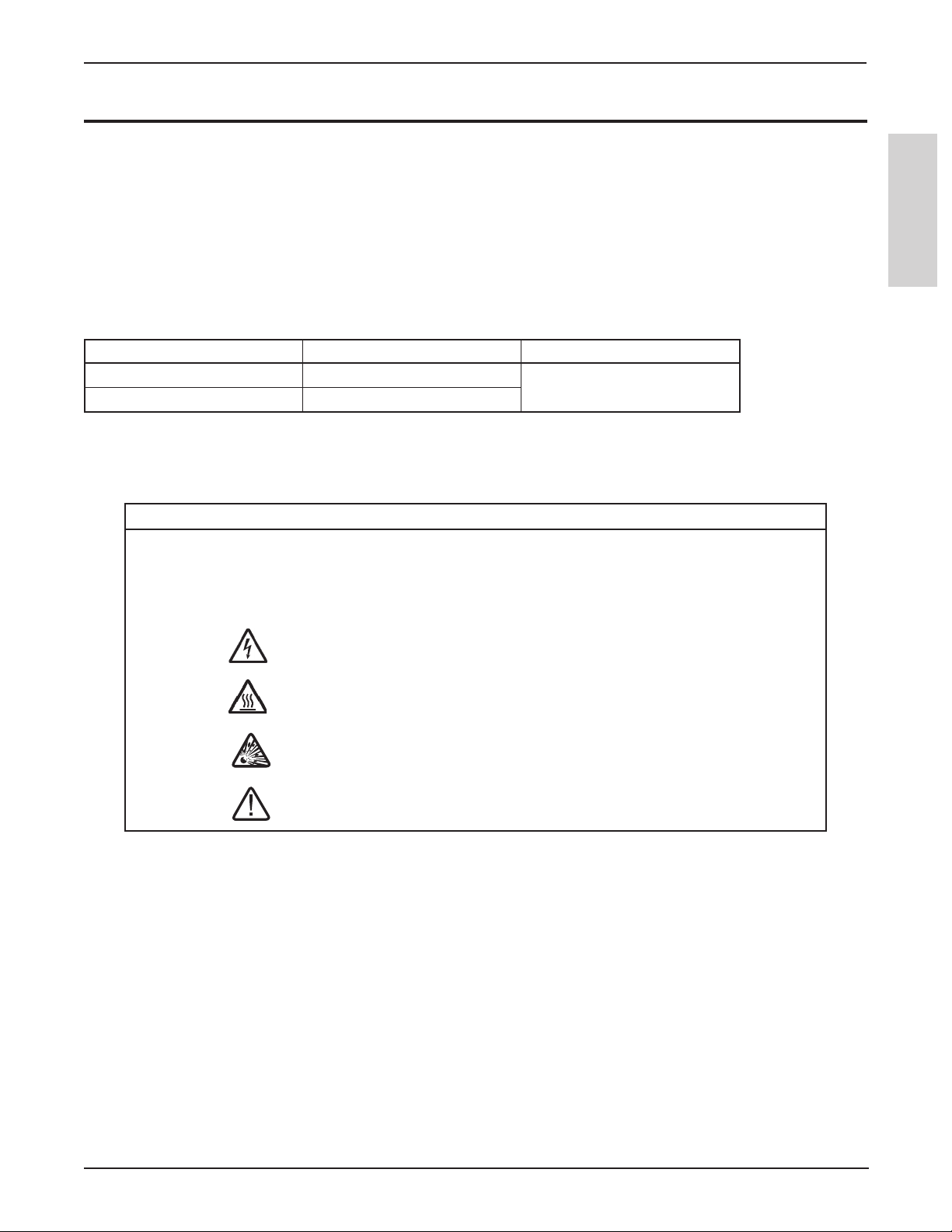
Explanation of Signal Words and Symbols in Safety Labels and Instructions
WARNING:
CAUTION:
Indicates a potentially hazardous situation, which if not avoided, could
result in death or serious injury and/or property damage.
Indicates a potentially hazardous situation, which if not avoided, may
result in minor or moderate injury and/or property damage.
(non-condensing)
ENGLISH
Warning: Hazardous Voltage
Warning: Hot Surface – High Temperature Lamp
Warning: High Pressure
Attention: Read Accompanying Documentation
© 3M 2011. All Rights Reserved.
9
Page 10

Operator’s Guide
3M™ Super Close Projection System SCP725
m WARNING
To reduce the risk associated with hazardous voltage:
• Do not operate this projector in wet environments or outdoors.
• Do not modify this projector or power cord.
• Do not remove any screws other than those specified in the lamp replacement instructions.
• Do not attempt to service the projector other than the lamp cartridge. There are no user serviceable
ENGLISH
parts inside the projector.
• Contact a 3M authorized service provider for service.
• Disconnect power cord when the projector is not in use for extended periods of time, during lamp
replacement, and while cleaning.
• Do not allow water or other liquids to enter the projector.
To reduce the risk associated with hazardous voltage and/or re:
• Replace power cord if damaged.
• Contact a 3M authorized service provider if the projector becomes damaged.
• Use a grounded extension cord with a rating at least equal to that of the projector.
• Connect this projector to a grounded outlet.
To reduce the risk associated with choking:
• Keep the battery and battery cover away from children and pets.
To reduce the risk associated with hazardous voltage, impact, tripping, or intense visible light:
• Do not use this projector around unsupervised children.
To reduce the risk associated with sharp objects, premature lamp failure, exposure to mercury:
• Always handle the fragile lamp module with care.
• Replace the lamp module when the lamp replacement message appears.
• Never replace the lamp module with a previously used lamp module.
• Remove the projector from the ceiling or wall mount before replacing the lamp.
To reduce the risk associated with permanent vision impairment:
• Do not allow a child under the age of 8 years to view 3D images.
10
© 3M 2011. All Rights Reserved.
Page 11

™
Super Close Projection System SCP725
3M
Operator’s Guide
m CAUTION
To reduce the risk associated with eye strain, nausea, dizziness, headache:
• Take a break every hour for 15 minutes.
• Do not view 3D images or 3D full motion videos while standing or walking.
• Only use 3D Active Glasses for viewing field sequential 3D projected images.
• View 3D image from at least 2 m (7 feet) or greater distance.
• Make sure the right-eye and left-eye images are properly synchronized using the 3D menu of the
projector.
To reduce the risk associated with falling:
• Do not view 3D images or 3D full motion videos while standing or walking.
• Do not allow anyone with a history of photosensitive diseases like epilepsy to wear 3D glasses or
view field-sequential 3D projected images.
• Do not wear 3D Active Glasses while walking or standing.
To reduce the risk associated with intense visible light:
• Avoid looking directly into the projector lens while the lamp is on.
To reduce the risk associated with impact of a falling projector:
• Use only the 3M brand wall/ceiling mounting hardware kit if wall or ceiling mounting is desired.
• Installation of the 3M brand wall/ceiling kit must only be performed by qualified personnel.
• Adhere strictly to the proper installation procedure as outlined in the installation instructions when
installing the 3M wall/ceiling kit.
• When not mounted, always operate the unit on a flat and sturdy surface.
ENGLISH
To reduce the risk associated with explosion, and/or chemicals from leaking battery:
• Use only with battery type AAA.
• Orient the battery’s plus (+) and minus (-) terminals according to the markings found on the remote
control.
• Do not leave the battery in the remote for an extended period of time.
• Do not heat, disassemble, short, recharge, or expose the batteries to fire or high temperature.
• Do not carry batteries loose in your pocket or purse.
• Avoid eye and skin contact in the event that battery would leak.
• Do not mix used and new batteries.
To reduce the risk associated with tripping, and/or impact:
• Position the power cord and cables so that they can not be tripped over.
To reduce the risk associated with environmental contamination:
• Dispose of mercury lamp, exhausted batteries, and other electronic components in accordance with
applicable federal, state and local regulations.
To reduce the risk associated with lamp rupture related hazards:
• In event of lamp rupture, call 3M authorized service provider for repair. Ruptured lamp repair is
not user serviceable.
• Wash your hands thoroughly if contact with ruptured lamp debris has taken place.
• Ventilate the area where the lamp rupture occurs. The lamp operates at high temperature.
To reduce the risk associated with hot surface of lamp cartridge:
• Before replacing the lamp, allow the lamp to cool for 60 minutes and then unplug the projector
from the electrical outlet.
To reduce the risk associated with environmental contamination due to mercury:
• Hg: Lamp contains mercury. Don’t throw in trash. Dispose according to local, state, or federal
laws. See www.lamprecycle.org or call 1-800-328-1371.
SAVE THESE INSTRUCTIONS
© 3M 2011. All Rights Reserved.
11
Page 12

Operator’s Guide
Safety Labels
The following safety labels are used on this product.
ENGLISH
3M™ Super Close Projection System SCP725
12
© 3M 2011. All Rights Reserved.
Page 13
™
Super Close Projection System SCP725
3M
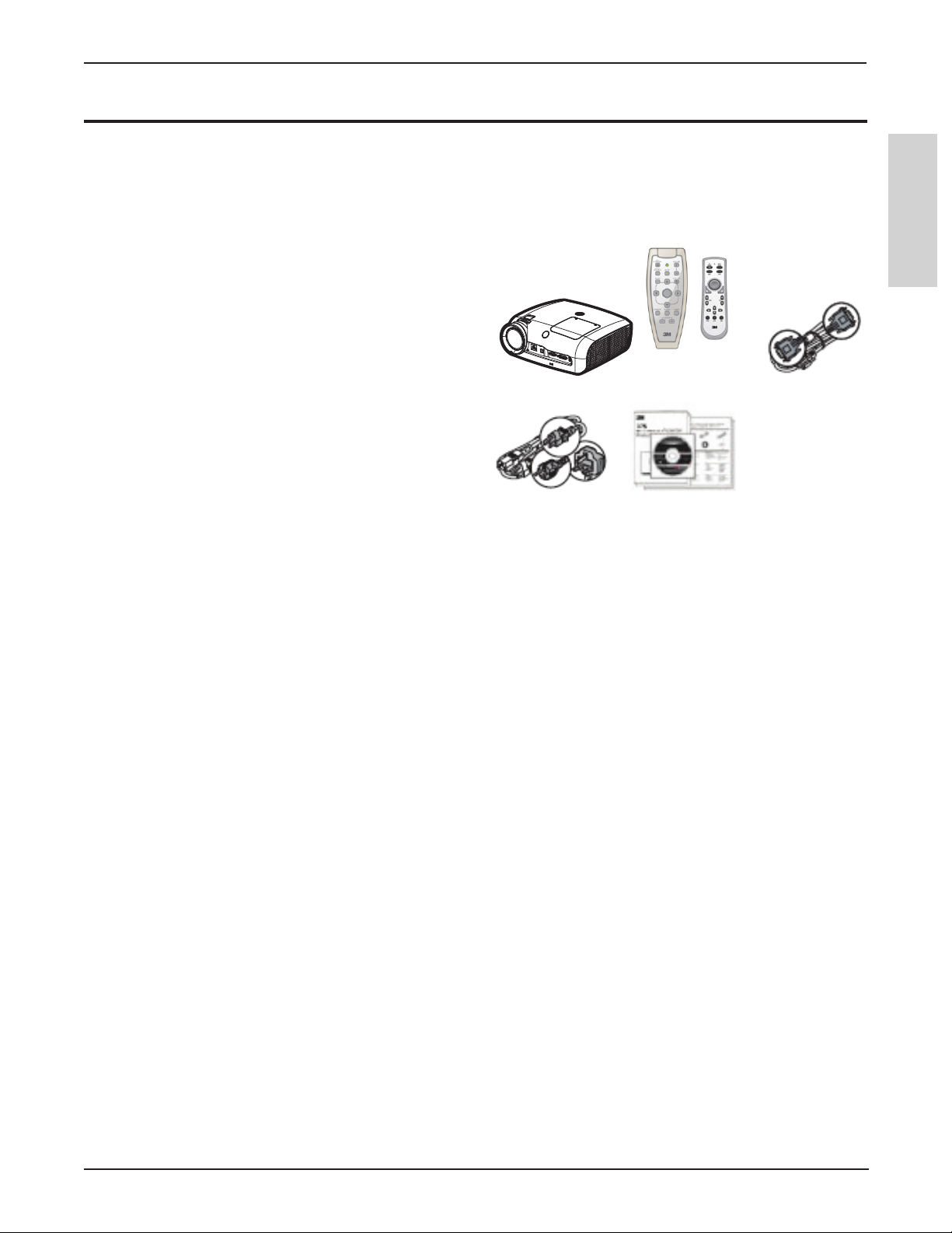
Contents of Shipping Box
Operator’s Guide
This projector is shipped with the necessary cables required for standard DVD player, PC or laptop computer
connections. Carefully unpack and verify that you have all of the items shown below. If any of these items are
missing, please contact your place of purchase.
The shipping carton contains the following items illustrated below. If any of these items are missing, please
contact your place of purchase.
1. Projector
2. Remote Control Transmitter (batteries included)
3. VGA to VGA cable, 1.8m (15-pin Male)
4. Power cord
5. Operator’s Guide CD
6. USB A-B cable, 1.8m (not shown)
1 2 3
4 5
Note: This projector is compatible with two different remote controls .
ENGLISH
Keep Your Packing Materials
Save the shipping box and packing materials in the event this product should require shipping to a 3M Service
Center for repair. Use packing material to protect projector.
What’s Next?
Take a few minutes to review the machine characteristics before you setup and operate the projector. We hope
you will enjoy using this high performance product in your classrooms, presentations and training sessions. This
product has been produced in accordance with 3M’s highest quality and safety standards to provide smooth and
trouble-free use in the years to come.
© 3M 2011. All Rights Reserved.
13
Page 14
Operator’s Guide
3M™ Super Close Projection System SCP725
Product Description
The 3M SCP725 integrates short-arc lamp and Digital Light Processing™ (DLP) technology. It accepts input
from computer and/or video sources and projects a bright image through 3M™ Vikuiti™ Super Close Projection
technology.
Machine Characteristics
ENGLISH
The 3M SCP725 offers the following features:
• Native Resolution 1024x768 XGA
• On-screen menu with 9 languages (English, French, Deutsch, Spanish, Italian, Japanese, Chinese Traditional,
Chinese Simplified, Korean)
• Lamp Life of 5000 hours (ECO mode)
• Lamp Life of 3000 hours (Bright mode)
• Image size: 30" to 150" diagonal
• Aspect Ratio: 4:3
• Digital keystone correction
• Vertical Lens Shift
• RS232 Control capable
• 3M Super Close Projection technology
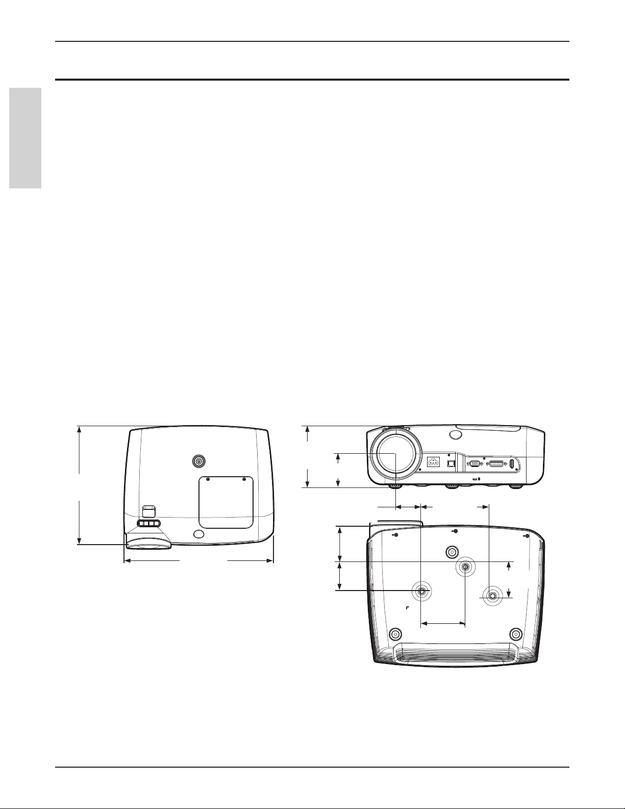
Dimensions
10.2 in.
359.1 cm
12.9 in.
326.6 cm
4.6 in.
116.2 cm
2.6 in.
65.1 mm
2.1 in.
54.0 mm
2.5 in.
63.4 cm
1.9 in.
47.5 cm
5.0 in.
126.6 cm
2.7 in.
68.0 mm
3.3 in.
82.639 cm
14
© 3M 2011. All Rights Reserved.
Page 15

™
)
Super Close Projection System SCP725
3M
Operator’s Guide
Projector Distance from Screen and Image Size
Refer to the chart below for the projector-to-screen distance and corresponding projected image size values.
Image Size Distance (D) Offset Min (S) Offset Max (S)
Diagonal Width Height (H) in mm in mm in mm
50 40 30 24 3/4 629 2 3/8 61 5 1/2 137
60 48 36 29 3/4 755 3 73 6 1/2 165
70 56 42 34 5/8 880 3 1/4 85 7 1/2 192
75 60 45 37 1/8 943 3 1/2 91 8 206
80 64 48 39 5/8 1006 3 3/4 98 8 3/4 219
90 72 54 44 1/2 1132 4 1/4 110 9 3/4 247
100 80 60 49 1/2 1258 4 3/4 122 10 3/4 274
150 120 90 74 1/4 1886 7 1/4 183 16 1/4 411
Vertical Lens Shift
The lens-shift feature will vertically offset the picture from 1¼ in. (30 mm) up to 4 ½ in. (117 mm)
depending on the projector-to-screen distance and size of the projected image. This adjustment is
typicallyusedwithwallmountapplicationsasane-adjustmenttotheverticalpositionoftheprojected
image. Turn the adjustment screw to vertically raise or lower the physical position of the lens. Refer to
the chart above for the offset values.
Note: The Lens-Shift adjustment screw does not adjust or change any keystone properties.
ENGLISH
2-1/2 in. (63mm
H
S
D
© 3M 2011. All Rights Reserved.
15
Page 16

Operator’s Guide
Parts Identification
1. Super Close Projection Lens
3M™ Super Close Projection System SCP725
2. Focus Adjustment
3. Lens-shift
4. Remote Control IR Sensor
5. Status Indicator Light
ENGLISH
6. Standby/On Button
7. Lamp Cover
8. Ventilation Slots
9. HDMI Port
10. Control Input
11. Computer/Component Input
™
12. Slot for Kensington
Lock
13. USB Port (For remote mouse functionality)
14. AC Power Cord Connection
15. Height Adjustment Foot
4
3
2
1
14
13
12
15
5
11
6
7
8
9
10
Projector Terminal Connections
AC Power USB
1 2 3 4 5
Computer
# Projector Panel Function
1 A/C Power Connect AC power cord to projector.
2 USB Connect projector USB (B-type) to computer USB port to control computer
pointer with remote control.
3 COMPUTER Input VIDEO signal from a computer source.
4 I/O Module Control Connect projector control port to computer serial port with RS232 adapter or
the 3M I/O Module and control the projector.
5 HDMI Connect the projector a HDMI video source or DVI-D video source. The
SCP725 does not connect audio through the HDMI port.
I/O Module Control
16
© 3M 2011. All Rights Reserved.
Page 17

™
Super Close Projection System SCP725
3M
Operator’s Guide
I/O Module Control Panel (optional accessory)
If your projector has the optional I/O Module installed, the projector functions can be operated from the I/O
Module Control Panel.
ENGLISH
1 2
4 3
5
6
# I/O Module Control Panel Function
1 ON/OFF Turns the projector on and off
2 Volume +/- Increases (+) or decreases (-) audio level
3 Source Switches the displayed input source. Switching order: Computer 1 =>
Computer 2 => S-Video => Video
4 Menu Displays the projector’s menu system.
5 Arrow Buttons Navigate up/down or left/right through projector’s Menu system.
6 ENTER
Select menu item and confirm menu selections
(Center of Arrow buttons)
Top Terminal Panel on I/O Module
Use the Top Terminal Panel to connect the projector to the I/O Module box.
Audio
Power
USB USB
Control Signal
To Projector
Audio
Out
2
31 4 5
I/O Module
# Top Terminal Panel Function
1 Audio Power Relay Audio power (from bottom terminal) through to speaker
amplifier.
2 USB (Hub) Connect two USB devices (like the projector’s remote mouse) to a
single USB port on computer connected to the I/O Module’s bottom
terminal panel.
3 CONTROL Connect IO/Module to projector I/O Module CONTROL terminal.
4 Signal Connect I/O Module to projector COMPUTER port.
5 Audio Out Connect IO/Module to external speakers or speakers in 3M Folding
Wall Mount FWMSV2.
© 3M 2011. All Rights Reserved.
17
Page 18

Operator’s Guide
3M™ Super Close Projection System SCP725
Bottom Terminal Panel on I/O Module
Use the Bottom Terminal Panel to connect the I/O Module box to the Computer/Video source.
1 2 3 4 5 6
ENGLISH
I/O Module
7 8
9
10 11 12 13
# Bottom Terminal Panel Function
1 Audio Power Supplies power to 3M Folding Wall Mount speakers from the power
supply included with the 3M Folding Wall Mount.
2 Computer2/Component2 Input for computer or component video device.
3 Serial RS-232 Passes control commands from a computer or control system to the
projector.
4 Video Input for composite video devices.
5 RCA Input R/L Right and Left Channel Audio Input.
6 Stereo Mini 2 Stereo Audio input for Computer2.
7 USB Connects the two devices connected to the top terminal panel USB
ports to a computer.
8 Ethernet Allow access to the projector control webpage and control command
over a network remote monitoring & control.
9 Computer1/ Component1 Input for computer or component video device.
10 Computer Out Output the signal from the Computer 1 port.
11 S-Video Video device input for S-video
12 Stereo Mini 1 Stereo Audio input
13 Audio Out Connects selected audio input to active speakers or audio amplifier.
18
© 3M 2011. All Rights Reserved.
Page 19

™
Super Close Projection System SCP725
3M
Operator’s Guide
Remote Control Functions
Use a USB cable to connect from the PC to the SCP725 or SCP I/O Module (if equipped) and aim the remote
control toward the projection screen or at the IR sensor on the projector. Press desired remote control button to
send a signal to the projector.
Note: This projector is compatible with two remote control transmitters.
ON/STANDBY ON: Press to turn projector ON.
ON/
STANDBY
MENU
ZOOM
INPUT/
SOURCE
OFF: Press to display confirmation message, press again to
switch projector to Standby mode.
Note: The confirmation message displays to ensure unit
MUTE
does not get turned off accidentally.
INPUT/ SOURCE Press for current input source. Press again to select different
computer/video input.
Computer 1/Component 1 –> Computer 2/Component 2 –>
RCA Composite Video –> S-Video –> HDMI]
Volume + Press to increase speaker volume.
Volume – Press to decrease speaker volume.
Mute Press to switch the audio sound ON or OFF.
VOL
Menu
L-Click
(top remote only)
R-Click
BLANK TIMERFREEZE
Up Arrow Moves cursor upward through menu items.
Press to display the Main Menu. When a menu is open, press
to exit menu.
Performs remote Left Mouse click function (when USB is
connected to projector USB)
Performs remote Right Mouse click function (when USB is
connected to projector USB).
Down Arrow Moves cursor downward through menu items.
Left Arrow
Right Arrow
Mouse Pad
Blank
Moves cursor left through menu items. Moves .ppt slides
backwards.
Moves cursor to right through menu items. Moves .ppt slides
forward.
Allows remote mouse functions. Allows Pan function when
in Zoom mode.
Press to replace projected image with black image. Press
again to return projection image.
Press to temporarily freeze movement on current image in
Freeze
motion. Press again to return to active image.
Note: This function is intended for a few minutes only.
Press to initiate a 10:00 minute digital timer. Press up/down
Timer
arrows to change timer clock by 1 minute intervals up to
99:00.
Zoom +
Zoom -
Trigger Button
(bottom remote only)
Press and hold to increase the size of the displayed image up
to 200 percent.
Press and hold to decrease size of the displayed image down
to 100 percent
Pull trigger for remote LEFT mouse button functions. In
menu mode, use for remote Enter / Select functions.
ENGLISH
Trigger button on
backside of remote
© 3M 2011. All Rights Reserved.
19
Page 20

Operator’s Guide
Installing Batteries in Remote Control
1. Push down on cover to unlatch it. Slide cover off.
2. Install same type of batteries with the correct
polarities.
3. Reinstall battery cover.
Note: Verify the battery cover is fully latched before
ENGLISH
using the remote control.
Setup and System Configuration
3M™ Super Close Projection System SCP725
[OR]
20
© 3M 2011. All Rights Reserved.
Page 21

™
Super Close Projection System SCP725
3M
Operating Instructions
Operator’s Guide
Projector Start Up
Read the Important Safeguards before operating the SCP725. After all cable connections have been completed,
refer to Setup and Configuration, the projector can be powered up.
For best results, please observe the following start up sequence.
1. Power ON all of the connected equipment.
2. Plug the supplied power cord into the AC inlet of the projector.
3. Press the On/Standby button on the projector or remote control. The lamp will turn on and an image will
appear and grow brighter on the screen.
4. If the security feature is activated, enter the 4-digit PIN code.
a. Press the left/right arrow to move the cursor through each PIN field.
b. Press the up/down arrows to change the value in each field.
c. Press the Trigger button on the remote to enter the PIN access code.
5. Check all ventilation slots and clear away any obstructions.
6. Extend or retract front adjustment foot to obtain best image height.
Note: Rotate foot for fine adjustment.
PIN Code
ENGLISH
7. Turn the focus adjustment (top of projector) to obtain the best image sharpness.
Stand By Mode
When an image is not being projected, place the unit into standby mode.
1. Press the On/Standby button on the Remote Control or the On/Off button on the I/O Box. When the
message “Press the power button to turn the unit off” displays, press the On/Standby button again.
2. The lamp will switch off and the power button will first turn red indicating the unit is in lockout and then
after 90 seconds the button turns amber to indicate the unit is in standby mode.
Note: In standby mode, the cooling fans will continue to run for 5 minutes and then turn off.
© 3M 2011. All Rights Reserved.
21
Page 22

Operator’s Guide
3M™ Super Close Projection System SCP725
Menu Navigation
To display the on screen menus, press the MENU button on the remote control or I/O Module. Use the remote
control Up/Down ARROW buttons to select the desired menu (see table below), then pull the TRIGGER button
(bottom of remote control) to display it.
Use the remote control ARROW buttons within a submenu to select the various options displayed on the screen,
then pull the TRIGGER button to initiate that option or setting.
ENGLISH
To exit an on-screen submenu, press the MENU button.
Main Menu
The main menu is the first system menu to display when the MENU button is pressed. Click on the menu icons
to display the desired submenu.
Main Menu
Menu Icon Menu Description
Input Menu – Select the desired computer or video input source.
Picture Menu – Adjust the following picture features: mode, brightness, contrast, color
intensity, tint, sharpness, video noise reduction, aspect ratio, and menu reset. Note: Displays
only when input source is connected.
Advanced Picture Menu – Adjust the following settings for the detected signal source: over
Advanced
scan, brightness/color, horizontal position, vertical position, frequency, phase, & menu reset.
Audio Menu – Adjust the following audio settings: volume, mute, audio input (stereo mini-1,
stereo mini-2, RCA), menu reset.
Setup Menu – Select or adjust the following settings: menu languages, auto shutoff timer,
keystone, lamp hours, lamp mode, fan mode, projection mode, factory reset, PIN code and
menu reset.
Information Menu – Display the current system information: input resolution, H/V
frequency, lamp hours, system hours, IP address/net mask/gateway for I/O module Ethernet
interface, user revision.
22
© 3M 2011. All Rights Reserved.
Page 23

™
Super Close Projection System SCP725
3M
Operator’s Guide
Input Menu
The Input Menu, shown below, is used to select the desired computer or video input source to be displayed on
the projector.
Input Input Source: Computer 1
✓
Computer 1 / Component 1
Computer 2 / Component 2
RCA Video
S-Video
HDMI
ENGLISH
Feature Description
Main Input Select the Input source to be displayed on the projector.
1. Computer 1 / Component 2 [Computer 1 = default]
2. Computer 2 / Component 2 [Displays only when I/O module is connected]
3. RCA Video (Composite video)
4. S-Video
5. HDMI
© 3M 2011. All Rights Reserved.
23
Page 24

Operator’s Guide
3M™ Super Close Projection System SCP725
Picture Menu
The Picture Menu, shown below, is used to adjust the picture settings to display the best possible image.
Picture Input Source: Computer 1
Picture Mode Enhanced Photo
Brightness 50 |·······················|
ENGLISH
Color 50 |·······················|
Hue 0 |·······················|
Sharpness 0 |·······················|
Video Noise Reduction On
Aspect Ratio Full Screen
Advanced
Reset
Feature Description Range Default
Picture Mode
Select the best mode to optimize the
projector image.
1. Max Brightness
2. Enhanced Photo
3. Enhanced
4. Photo
Brightness
Contrast
Color *
(see note)
Hue *
(see note)
Sharpness
Adjust brightness (low to high) of
displayed image
Adjust the contrast (dark to light) in the
displayed image
Adjust the intensity of color in the
displayed image
Adjust the balance of red (-) to green (+)
for video signals.
Adjust the displayed image to look sharper
or softer
Video Noise Reduction Turn noise reduction ON or OFF N/A Off
Aspect Ratio
Set aspect ratio to: [Full Screen or 16:9 or
Native]
Navigate to the Advanced picture setting
Advanced
menu. This option is for Computer/
Component input and only displays when
the I/O Module is connected.
Reset Reset values in this menu only N/A N/A
05 tsartnoC |·······················|
VGA-Max Brightness
N/A
Video-Enhanced Photo
0–100 50
0–100 50
0–100 50
-15–+15 0
-15–+15 0
N/A Full Screen
N/A N/A
* Note: Tint/Hue can only be adjusted for S-Video and RCA video input signals
24
© 3M 2011. All Rights Reserved.
Page 25

™
Super Close Projection System SCP725
3M
Operator’s Guide
Advanced Picture Menu
The Picture Menu with the Advanced option selected, shown below, is used to adjust the projected image for
Computer and Component inputs only.
Picture Input Source: Computer 1
Over Scan 97 |···········●············|
Color / Brightness 10 |·······················●|
Horizontal Position 0 |···········●············|
Vertical Position 0 |···········●············|
Frequency 0 |···········●············|
Phase 0 |···········●············|
3D Control Off
3D Reverse Off
Reset ►
Feature Description Range Default
Over Scan
Brightness / Color
Horizontal
Position
Vertical Position
Frequency
Phase
3D Control
Adjust cropping of image boundaries from 90th to
100th percentile (increments of 1 percent).
Adjust the white peaking value of the DMD.
(0 = lowest white peaking value, 10 = highest value)
Adjust horizontal position of projected image.
(Only for Computer 1 or Computer 2 input source)
Adjust vertical position of projected image.
(Only for Computer 1 or Computer 2 input source)
Adjust the horizontal width of the projected image.
(Only for Computer 1 or Computer 2 input source)
Adjust clock phase to reduce image distortion.
(Only for Computer 1 or Computer 2 input source)
Turns on or off TI 3D DLP-Link. On reverts to Off
but Always On is not affected when the projector is
removed from its power source.
90–100
0–10
N/A 0
N/A 0
-50–+50 0
-15–+15 0
On / Off /
Always On
Turn on 3D Reverse. 3D Reverse flips the order of
the left and right image for the eyes in the event they
3D Reverse
are out of sync. The left and right image are out of
sync when the images in the background appear closer
than the image is the foreground. On reverts to Off
On / Off /
Always On
but Always On is not affected when the projector is
removed from its power source.
Reset Reset values in this menu only N/A N/A
Video = 97
VGA = 100
Computer = 10
Video = 3
N/A
N/A
ENGLISH
© 3M 2011. All Rights Reserved.
25
Page 26

Operator’s Guide
3M™ Super Close Projection System SCP725
Audio Menu
(Menu displays only if I/O Module is connected)
The Audio Menu, shown below, is used to adjust the audio settings and select the audio input source to play
through the projector.
Audio Input Source: Computer 1
ENGLISH
Volume 10 |·······················|
Mute Off
Audio Input √ Stereo Mini 1
Stereo Mini 2
RCA
teseR
Feature Description Range Default
Volume Adjust volume level (0 = muted, 20 = full volume) 0–20 10
Mute Turn mute mode ON and OFF N/A OFF
Select the audio input source to process.
Audio Input
Stereo Mini 1 – VGA/Component
N/A PC
Stereo Mini 2 – VGA2/Component
RCA – S-Video/Component
Reset Reset values in this menu only N/A N/A
26
© 3M 2011. All Rights Reserved.
Page 27

™
Super Close Projection System SCP725
3M
Setup Menu
The Setup Menu, shown below, is used to configure the basic projector operating parameters.
Setup Input Source: Computer 1
Language English
Auto Shutoff Minutes Off |······················|
Keystone 0 |······················|
Reset Lamp Hrs
Lamp Mode Normal
Fan Mode Normal
Projection Mode Front Projection
Factory Reset All
Advanced
teseR
Operator’s Guide
ENGLISH
ENGLISH
Feature Description Range Default
Language Select the language for menu displays
[1-English, 2-French, 3-Spanish, 4-German, 5-Italian,
6-Japanese, 7-Chinese Traditional, 8-Chinese Simplified,
N/A English
9-Korean]
Auto Shutoff
Minutes
Set the number of idle minutes (no input source detected
and no commands issued) before the projector will
automatically shut off.
0–60 10
Keystone Vertical keystone adjustment. -40 – +40 0
Reset Lamp Hours Reset lamp hour status indicator. See Information Menu. N/A N/A
Lamp Mode Bright, Normal, ECO N/A Normal
Fan Mode Normal, High N/A Normal
Projection Mode
1-Front Projection, 2-Rear Projection, 3-Front Ceiling,
4-Rear Ceiling
N/A
Front
Projection
Factory Reset Reset all menu items to FACTORY DEFAULT settings N/A N/A
Advanced Select the Advanced Setup Menu. N/A N/A
Reset Reset values in this menu only N/A N/A
© 3M 2011. All Rights Reserved.
27
27
Page 28

Operator’s Guide
Advanced Setup Input Source: Computer 1
PIN Authentication Off ►
New PIN
▄ ▄ ▄ ▄
3M™ Super Close Projection System SCP725
Advanced Setup Menu
The Advanced Setup Menu, shown below, is used to initiate the PIN code feature (turn On/Off) and set the
PIN code.
ENGLISH
ENGLISH
Change PIN ►
Network Control Off ►
Closed Captioning Off ►
De-Magnify 0 |···········●············|
Pan Horizontal 0 |···········●············|
Pan Vertical 0 |···········●············|
Feature Description Range Default
PIN Authentication Turn the PIN code security feature On or Off. N/A Off
Change the 4-digit PIN access code as desired.
Set PIN code
Note: When PIN security is enabled, the PIN access
0–9 3349
code will automatically set to the default value 3349.
Turns the network control function on and off. The
network control feature allows a computer to open
the control web page on I/O module and control the
projector.
To view the control web page, connect the I/O
Network Control
module into the local area network and type the
I/O module's IP address into the address bar of a
web browser. (The IP address can be found in the
projector’s information menu. See the next page.)
The control web page will display. A RS-232 and
network control guide is available at www.mmm.
com\meetings in the Technical Documents section.
Turns on Closed Captioning. CC1, CC2, CC3, and
Closed Captioning
CC4 are the different Close Caption channels. CC1 is
the primary channel for most content. The content on
CC2, CC3, and CC4 may vary on video source.
De-Magnify
Reduces the image size from 100% to 50% of the
projected image size.
Pan Horizontal Positions the image horizontally -5 to +5 0
Pan Vertical Positions the image vertically -5 to +5 0
Reset Reset setting to factory default.
On/Off On
Off / CC1 /
CC2 / CC3
Off
/ CC4
50 to 100 100
28
28
© 3M 2011. All Rights Reserved.
Page 29

™
Super Close Projection System SCP725
3M
Operator’s Guide
Information Menu
The Information Menu, shown below, is used to display current projector configuration settings.
Information Input Source: Computer 1
Input Resolution 1024 x 768
H Frequency 31.75 KHz
V Frequency 60 Hz
Lamp Hours 1235
System Hours 2356
IP Address 192.168.1.10
Net Mask 255.255.255.0
Gateway 192.168.1.1
User Ver. 0.0.8
Feature Description
Input Resolution Displays the current input Resolution
H Frequency Displays the current input H-Frequency
V Frequency Displays the current input V-Frequency
Lamp Hours Displays the current lamp operating hours for the installed lamp
System Hours Displays the current total system time accumulated
IP Address *
(see note)
Net Mask *
(see note)
Gateway *
(see note)
Displays the current IP Address for the I/O module Ethernet interface
Displays the current Net Mask for the I/O module Ethernet interface
Displays the current gateway for the I/O module Ethernet interface
User Revision Displays the current User Version
ENGLISH
* Note: This field displays only when the I/O Module is connected.
© 3M 2011. All Rights Reserved.
29
Page 30

Operator’s Guide
3M™ Super Close Projection System SCP725
Machine Specifications
Item Specification
Bright Mode: Typical 34 dB(A)
Acoustic Noise Level
ENGLISH
Auto Detect & Install
Computer Compatibility
Conditions for usage environment
Dimensions 328.94 x 264.0 x 116.43 mm (13.2 x 10.6 x 4.7 inches)
DMD Native Resolution 1024x768 (XGA)
Focus Manual Adjustment
Input / Output Terminals
Input rating 100-240V AC, 50-60 Hz, 4.0A
Lamp Life
Languages
Lens Focal Length = 8.9 mm
Power Consumption 300W normal operation, 5W standby mode
Video Compatibility
Wall/Ceiling Mount capability Three screw holes
Weight 4.5kg (10 lbs)
Normal Mode: Typical 32 dB(A)
ECO Mode: Typical 28.5 dB(A)
Automatically recognizes the connection of I/O module
Automatically saves user adjustments
Horizontal Sync: 69 kHz
Vertical Sync: 85 Hz
Rel Humidity:10-80%
Altitude: 0-2286m (0-6000ft)
Temperature: /10-35C (50-95F)
HDMI connector
VGA (mini D-sub 15-pin) connector
Control connector
USB (A-B)
AC power outlet
3000 hrs at 230W Bright mode
5000 hrs at 180W ECO mode
English, French, Spanish, Deutsch, Italian, Japanese, Chinese
Traditional, Chinese Simplified, Korean
NTSC: M, N, 3.58Mz, 4.43 MHz
PAL: B, D, G, H, I, M, N
SECAM
Note: Designs and specifications are subject to change without notice.
30
© 3M 2011. All Rights Reserved.
Page 31

™
Super Close Projection System SCP725
3M
Maintenance
Operator’s Guide
Lamp Replacement
11
10
9
8
ENGLISH
ENGLISH
12
1
2
3
4
57
6
Hg
www.lamprecycle.org
Note: Refer to the Setup Menu to reset the lamp hour timer after replacing the lamp.
© 3M 2011. All Rights Reserved.
31
Page 32

Operator’s Guide
3M™ Super Close Projection System SCP725
Cleaning the Air Vents
For best performance, 3M recommends that you periodically dust the projector and vacuum all air vents on the
projector.
Follow the procedures below.
1. Return projector to standby mode. After the Standby
button turns amber and the fan stops, unplug the
ENGLISH
power cord from the wall outlet.
2. When dust or dirt appears on the projector’s top
surface or around the air vents, clean these areas
before operating the projector.
a. Wipe the top surface with a clean/dry cloth or use
a vacuum cleaner.
b. Vacuum the intake air vent while gently tapping
on the vent slots to dislodge any dirt.
c. Vacuum the exhaust air vent while gently tapping
on the vent slots to dislodge any dirt.
3. Plug in the power cord and press the standby button
to power on projector. Test unit to verify it operates
correctly.
a
c
b
32
© 3M 2011. All Rights Reserved.
Page 33

™
2
1
Super Close Projection System SCP725
3M
Operator’s Guide
Cleaning the Lamp Module and Lamp Compartment
For best lamp performance, there must be adequate air flow through and around the lamp module. A build up of
dust or dirt will reduce the air flow and shorten lamp life and lamp performance. 3M recommends at every lamp
change or at least once a year that air vents, lamp module and lamp compartment be cleaned with a vacuum.
Follow the procedure below.
1. Unscrew lamp module retaining screws and carefully remove lamp module.
2. Vacuum the lamp cavity to remove all dislodged dust.
ENGLISH
3. Vacuum the lamp inlet and exhaust vents to clear any dust or dirt build up.
Important Note: Do not touch the glass reflector or the bulb. If oils from your skin transfer to the glass it will
weaken the heat resistant properties of the reflector/bulb and significantly shorten the lamp’s life.
© 3M 2011. All Rights Reserved.
33
Page 34

Operator’s Guide
4. Install the lamp taking care to seat it fully into the lamp socket connection and tighten the lamp retaining
screws.
ENGLISH
ENGLISH
5. Replace the lamp door and secure it with the retaining screws.
3M™ Super Close Projection System SCP725
6. Verify the projector operates correctly. Plug in power cord and press the standby button to power on projector.
Note: If the lamp door is not installed correctly, the projector will not power on.
34
© 3M 2011. All Rights Reserved.
Page 35
™
Super Close Projection System SCP725
3M
Troubleshooting
Operator’s Guide
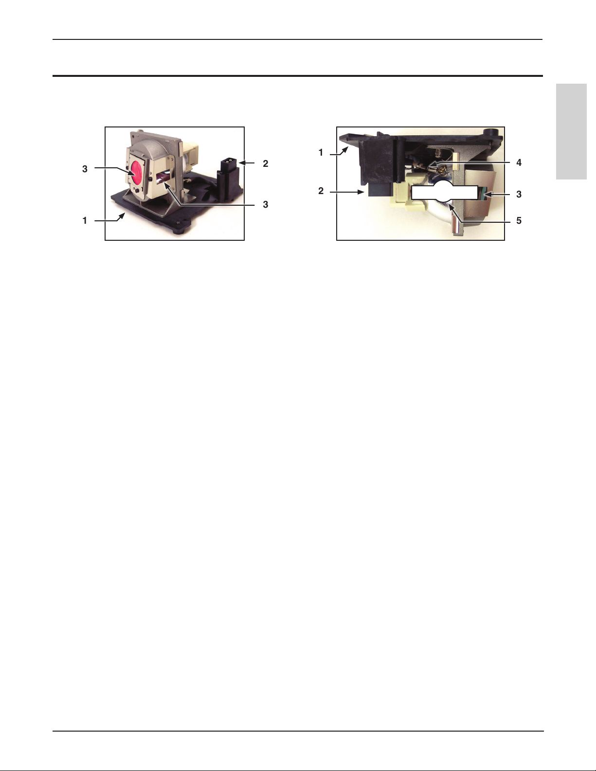
Identifying an Expired Lamp Module
Lamp Module Parts
1
3
1
1. Top of Lamp Module
2. Lamp Connector
3. Air Vents
4. Lamp Wires
5. Bulb Envelope - This is the shape of the bulb inside the lamp module.
Visible Indications of an Expired Lamp
The following five visible indicators help you recognize an expired lamp.
2
2
3
ENGLISH
4
3
5
1. Cloudy Bulb – A cloudy bulb may reduce the image brightness. The lamp will appear to have white or black
deposits on the inside of the bulb. These deposits are a sign of normal wear and tear. Replace the lamp if the
brightness is inadequate.
2. Disconnected or broken wires – If the lamp wires are broken, the lamp will not ignite. Replace the lamp if the
lamp wires are broken
3. Deformed Bulb – A deformed bulb will reduce the image brightness. A bulb is deformed when the bulb
envelope expands into an irregular, round shape. Replace the bulb if it becomes deformed.
4. Debris on Bulb End – If the lamp will not ignite, the bulb seal may have broken. When bulb seal is broken,
debris from the bulb will form at the break. Most of the times, this is at the bulb tip.
5. Broken Bulb – The lamp will not ignite if it is broken. Sometimes you will hear an abnormal sound when
you try to start the projector. Please refer to the Safety Instructions for more information about handling
broken bulbs.
© 3M 2011. All Rights Reserved.
35
Page 36

Operator’s Guide
3M™ Super Close Projection System SCP725
I/O Module Troubleshooting
Symptom Possible Cause Solution
The Standby button on the I/O
module does not light while the
projector is powered on.
ENGLISH
Projector Troubleshooting
Symptom Standby Button State Possible Cause Action
The projector will not turn
on
Off
The communication cable is not
connected or is damaged.
The projector does not have power. See projector troubleshooting
The power cord is not
connected to projector and
an electrical outlet.
The lamp door is not
installed, or is not
properly fastened down.
The projector has
overheated and has
automatically shut down.
The electrical outlet does
not have power
The projector’s power unit
has stopped working
Connect a communication cable (15
pin to 15 pin) from the projector to
the I/O module.
Insert the power cord into
electrical outlet.
Make sure the lamp
door is in place and
fastened down as shown
in the lamp replacement
instruction. See page 31.
Allow the projector cool
down. Once cooled down,
the projector will regain
power and the standby
button will light up. Clean
the projector’s air vents as
mention the maintenance
section.
Connect the projector to
an electric outlet that has
power. You can the test
the outlet using another
electrical appliance to
confirm that it has power.
Contact 3M for service.
36
© 3M 2011. All Rights Reserved.
Page 37

™
Super Close Projection System SCP725
3M
Symptom Standby Button State Possible Cause Action
The projector is cooling
down.
Red
Wait until the projector
completes its cooling
cycle. Once the Standby
button turns amber, you
can press the Standby
button again.
The lamp has expired Replace the Lamp and
press the Standby button
The lamp will not ignite
Orange
The lamp ballast may
to start the projector.
Contact 3M for service.
have stopped functioning.
There is a problem with
one of the cooling fans.
Flashes RED once every
second
Follow the maintenance
procedure on page 31 and
try starting the projector
again. If cleaning does
not resolve the problem,
contact 3M for service.
Flashes RED twice every
second
The projector has
overheated due to elevated
ambient temperature or
altitude, or blocked air
vents.
Follow the maintenance
procedure on page 31.
Unplug the power cord
and reconnect and then
try again. If cleaning does
not resolve the problem,
contact 3M for service.
The lamp will not ignite
or has turned off.
Flashes RED four times
every second
The projector’s
processor had a
communication error
due to electromagnetic
interference on the
communication cable
connecting the Control
port on the projector
and I/O module or poor
quality communication
cable.
Make sure the cable
connecting the Control
Port on the projector
to the I/O module does
not cross power cables
or other communication
cables. If it does, reroute
the cables so that they
do not cross. If the
communication cable
between the projector and
the I/O module is longer
than 4m (13 ft), consider
using the 3M I/O Module
Cable Extender P/N:
78-6972-0027-3.
Operator’s Guide
ENGLISH
© 3M 2011. All Rights Reserved.
37
Page 38

Operator’s Guide
Symptom Standby Button State Possible Cause Action
The desired input source
is not selected.
The cables from the input
source are not connected.
No image Green
ENGLISH
Noise in the image Green
Noise in the computer
image
No audio from speakers Green
The image is dark or dim Green
Green
The input source is
not turned on or not
displaying an image. (e.g.
If a notebook computer,
the external monitor port
is not turned on).
The video cable adds
noise to the signal
because it is not properly
terminated, too long
or lacks adequate
electromagnetic shielding.
The projector’s Frequency
and Phase settings are not
properly set.
The projector does not
have speakers.
The audio cable is
connected to the wrong
audio input.
The audio amplified in the
3M Folding Wall Mount
is not connected to a
power supply.
The audio source or the
speakers are muted
The brightness setting is
too low.
The lamp needs to be
replaced.
3M™ Super Close Projection System SCP725
Press the remote control
Input button to select a
desired input source.
Connect the cable to
correct input source.
Turn on input source.
Shorten the cable between
the video source and the
system or add a video
amplifier between the
video source and the long
cable.
Adjust Frequency and
Phase setting in the
Advanced Picture Menu
until noise is reduced or
eliminated.
Connect the audio cable
to correct input source or
change audio/video input
assignment settings in the
projector’s Audio menu
The I/O Module does
not supply power for
audio. The power adapter
included with the folding
wall mount must be
connected to the Audio
Power port on the bottom
of the I/O Module and
a cable from the Audio
Power port on the top
of the I/O Module to
the power input on the
folding wall mount.
Turn off mute on the
audio source
Adjust the brightness
Replace lamp.
38
© 3M 2011. All Rights Reserved.
Page 39

™
Super Close Projection System SCP725
3M
Symptom Standby Button State Possible Cause Action
Desired input source
cannot be detected
The input source is not
active. A signal must be
present for the input to be
selected.
The input device (e.g.
Connect an active input
source to unit.
Turn on input source.
computer, DVD player,
etc.) is not turned on.
The remote control does
not work
The remote control is not
facing the remote control
sensor.
The remote control is too
far from the sensor
An obstruction is between
the remote control and the
Face the remote control
toward the remote control
sensor.
Operate the remote
control within 5 meters.
Remove obstacle.
sensor.
The remote control’s
Correctly insert batteries.
batteries are exhausted or
inserted wrong.
Operator’s Guide
ENGLISH
Projector Indicator Lights
Mode Indicator Signal on Projector
Stand by Orange LED (always ON)
Lamp Strike Orange LED (Flashing)
Normal Operations Green LED (always ON)
Fan Error Red LED (One flash every second) (•••)
Thermal Error Red LED (Two flashes every second) ( •••••• )
Communication Error Red LED (Four flashes every second) ( •••••••••••• )
Cooling (Lock Out) Red LED (Solid light)
I/O Module Indicator Lights
Mode Indicator Signals on I/O Model Box
Stand by Orange LED (always ON)
Normal Operations Green LED (always ON)
Cooling (Lock Out) Red LED (Solid light)
© 3M 2011. All Rights Reserved.
39
Page 40

Operator’s Guide
3M™ Super Close Projection System SCP725
Replacement Parts and Accessories
Replacement Parts
Name of Part 3M Part Number
VGA Cable, 1.8 m 78-8134-7029-7
Remote Control 78-8134-7200-4
ENGLISH
SCP725/SCP725W Lamp Replacement 78-6969-9996-6
Optional Accessories (not shown)
Name of Part 3M Part Number
3M Fixed Wall Mount SCPFXW.V2 78-6969-9986-7
3M Folding Wall Mount with Speakers SCPWMS.V2 78-6969-9988-3
3M I/O Module V3 78-6972-0012-5
RS232 Adapter for projector control without the I/O Module 78-6969-9934-7
3M Security Kit 78-6969-9961-0
Wall Mount Bracket for Block and Stud Walls 78-6969-9962-8
VGA Cable, 3.5 m (11.5 ft) 78-8134-7218-6
USB Cable, 3.5 m (11.5 ft) 78-8134-7219-4
Control Cable 15 pin DB, 3.5 m (11.5 ft) 78-8134-7220-2
40
© 3M 2011. All Rights Reserved.
Page 41

™
Super Close Projection System SCP725
3M
Operator’s Guide
ENGLISH
© 3M 2011. All Rights Reserved.
41
Page 42

Operator’s Guide
ENGLISH
3M™ Super Close Projection System SCP725
42
© 3M 2011. All Rights Reserved.
Page 43

™
Super Close Projection System SCP725
3M
Operator’s Guide
ENGLISH
© 3M 2011. All Rights Reserved.
43
Page 44

ENGLISHENGLISH
Important Notice
All statements, technical information, and recommendations related to 3M’s products are based on information believed to be reliable, but the accuracy or completeness is not guaranteed. Before using this
product, you must evaluate it and determine if it is suitable for your intended application. You assume all
risks and liability associated with such use. Any statements related to the product which are not contained in 3M’s current publications, or any contrary statements contained on your purchase order shall
havenoforceoreffectunlessexpresslysetforthinawrittenagreementsignedbyanauthorizedofcer
of 3M.
Technical Support Contact:
3M Austin Center 3M Canada 3M Mexico, S.a. de C.V. 3M Europe
Building A145-5N-01 P.O. box 5757 Apartado Postal 14-139 Boulevard de l'Oise
6801 River Place Blvd. London, Ontario Mexico, D.F. 07000 95006 Cerge Pontoise Cedex
Austin, TX 78726-9000 N6A 4TI Mexico France
Please recycle.
Litho in USA
@3M 2011
 Loading...