

Page 1
3
FUNCTION
VIEW
OUT WBGT
start
SELECT
MONITOR / log
°C/°F
time base
°F
WIBGET™ Heat Stress Monitor RSS-214
User Instructions
(Keep these User Instructions for reference)
Moniteur de stress thermique RSS-214 WIBGET
Directives d’utilisation
(Conserver ces directives à titre de référence)
Monitor de estrés térmico WIBGET™ RSS-214
Instrucciones de uso
(Conserve estas Instrucciones de uso para referencia futura.)
™
WIBGET
Instruções de Uso
(Guarde estas Instruções de Uso para referência futura)
RSS-214 Monitor de Sobrecarga Térmica
™
Page 2

2
Page 3

TABLE OF CONTENTS
GENERAL SAFETY INFORMATION 4
Intended Use 4
List of Warnings and Cautions 4
USE INSTRUCTIONS AND LIMITATIONS 5
General Description 5
SPECIFICATIONS 6
WBGT 7
SETUP 7
Sensor Installation 7
Wet Bulb Preparation 7
Location and Environment 7
OPERATING INSTRUCTIONS 7
Power On/Off 8
Self-Diagnostics 8
Monitor Mode 8
Analog/Recorder Output (monitor mode only) 8
DATA LOGGING (Optional) 8
Setting and Viewing Calendar/Clock 9
Log Mode 9
Demand Logging 9
View While Logging 9
Exit Data Logging 9
DOWNLOADING DATA 9
System Requirements 9
Installing WIBGET Heat Stress Monitor Software 9
Downloading Data 10
MAINTENANCE 11
Wet Bulb 11
Wick Replacement 11
Water Treatment 11
Cleaning 11
Storage 11
BATTERY 11
Charging 11
Replacement 11
CALIBRATION 11
TROUBLESHOOTING 12
PRODUCTS, ACCESSORIES AND PARTS 12
WARRANTY 13
FOR MORE INFORMATION 13
Exit Data Logging Mode
and Return to Monitor Mode 9
3
Page 4

GENERAL SAFETY INFORMATION
Intended Use
™
The 3M
WIBGET™ Heat Stress Monitor RSS-214 is designed to measure environmental factors that can contribute to heat stress.
List of Warnings and Cautions within these User Instructions
WARNING
This monitor helps to measure certain environmental factors that can contribute to heat stress. Misuse may result in sickness or death. For proper use, see
supervisor or User Instructions, or call 3M in U.S.A., 1-800-243-4630. In Canada, call Technical Service at 1-800-267-4414.
Each person using this equipment must read and understand the information in these User Instructions. Use of this equipment by untrained or unqualified persons, or use
that is not in accordance with these User Instructions, may adversely affect product performance and result in sickness or death.
Use only for monitoring environmental factors which the sensors and instrument are designed to monitor. Failure to do so may adversely affect product performance and result
in sickness or death. For proper use, see supervisor or User Instructions, or call 3M in U.S.A., 1-800-243-4630. In Canada, call Technical Service at 1-800-267-4414.
Each time the unit is turned on, it performs a self-test. If the self-test fails, or an error code is displayed, do not use. Doing so may adversely affect product performance
and result in sickness or death.
The RSS-214DL RS 232 serial data output port must be used in a non-hazardous area only. Using the data output port is not an intrinsically safe operation.
Failure to
do so may result in sickness or death.
Never alter or modify this instrument. Substitution of components may impair intrinsic safety. Doing so may adversely affect product performance and result in sickness or death.
Repair or replace parts only with the 3M components approved for this unit.
Failure to do so may adversely affect product performance and result in sickness or death.
Battery must be replaced in a non-hazardous area only. Battery replacement is not an intrinsically safe operation. Use only approved battery. Failure to do so may
result in sickness or death.
Only charge the instrument in non-hazardous areas using a 3M battery charger (AC adapter). Battery charging and operating with AC adapter is not an intrinsically safe
operation. Do not attempt to charge alkaline batteries. Doing so may adversely affect product performance and result in sickness or death.
CAUTION
Do not twist sensors once inserted into the base unit. Doing so may damage the sensor or sensor connector.
The wet bulb wick must remain wet during operation to help maintain the accuracy of the sensor.
Keep all connectors clean and dry. If a connector becomes wet, it must be thoroughly dried prior to instrument usage. Condition of the sensor receptacles may be tested by
removing all sensors, turning the unit on and checking that all functions read 0.0 ± 0.3 °C or 32.0 ± 0.5 °F. If these are not the readings, do not use until the reason has
been determined and corrected.
Do not expose dry bulb (DB) to temperatures above 65 °C (150 °F). This may damage the base unit. To monitor environments above 65 °C (150 °F), use a remote sensor
set accessory and relocate the base unit to a cooler area.
Avoid the use of harsh cleaning materials, abrasives and other organic solvents. Such materials may permanently scratch the surfaces and damage the display window,
labels, or monitor housing.
Observe proper polarity when inserting the battery. Polarity is marked on the inside of the battery compartment.
This instrument may contain a nickel metal hydride (NiMH) battery. Dispose of battery in accordance with local regulations.
4
Page 5
USE INSTRUCTIONS AND LIMITATIONS
FUNCTION
VIEW
OUT WBGT
start
SELECT
MONITOR / log
°C/°F
time base
°F
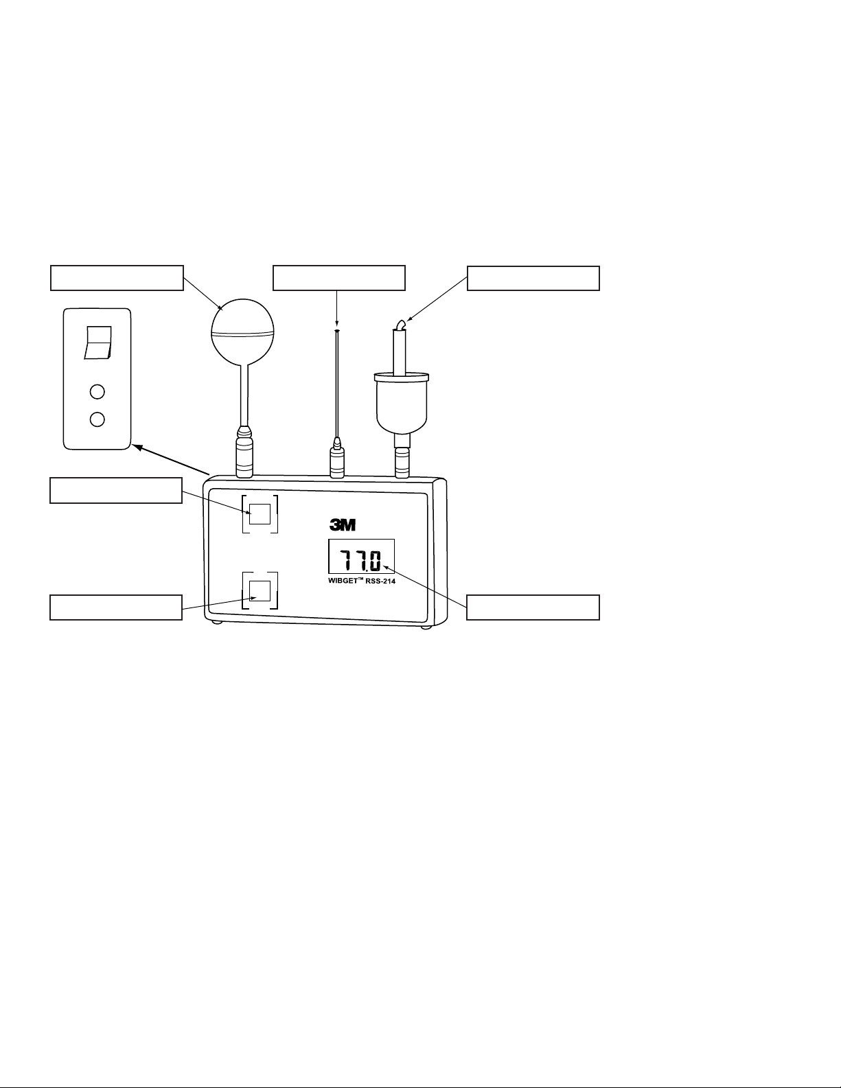
Function Button
Globe Sensor Dry Bulb Sensor
Wet Bulb Sensor
LCD DisplaySelect Button
ON
OFF
Analog
Output
0-1V
Charger
12vdc
Important
Before use, each person using this equipment must read and understand these User Instructions. Keep these User Instructions for reference.
General Description
These User Instructions apply to the 3M™ WIBGET Heat Stress Monitor RSS-214. It is a hand held microprocessor-based Wet Bulb Globe Thermometer designed to
measure certain environmental factors that can contribute to heat stress. An internal microprocessor controls the indication and response to the signals received from the
sensors mounted on top of the unit. When turned on it continuously monitors the ambient air.
The WIBGET monitor is a battery-powered unit utilizing a 9-volt rechargeable nickel metal hydride (NiMH) battery or replaceable 9-volt non-rechargeable alkaline battery. It is
designed to be intrinsically safe when powered by batteries. The WIBGET monitor is CSA certified intrinsically safe for Class I, Div. I, Groups A,B,C,and D Hazardous Locations.
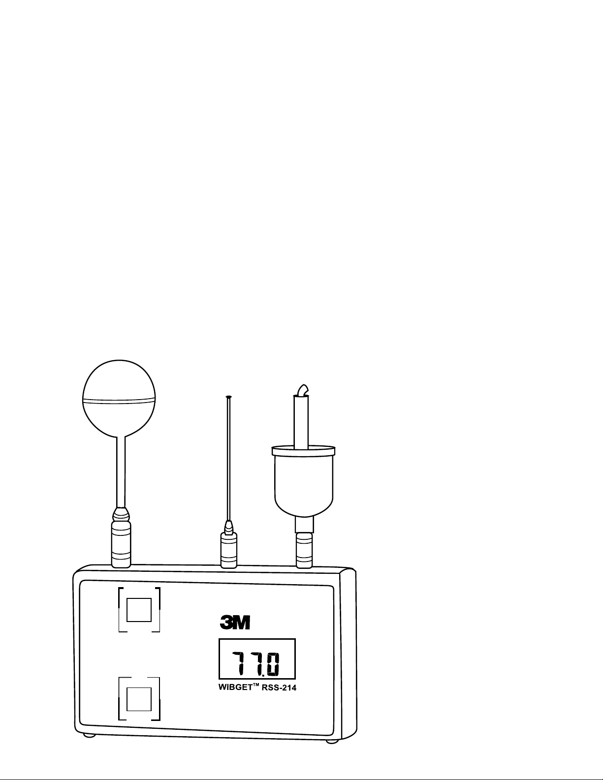
The components of the WIBGET monitor are assembled in a plastic housing 3.75 H x 6.2 W x 1.75 D in. (Fig. 1). Located on the front face of the unit are the display (LCD)
and the FUNCTION and SELECT buttons. On the left side of the unit are the On/Off switch, analog output, and charger jacks. On top of the unit are the sensor connector
pins for the Globe (GT), Dry Bulb (DB), and Wet Bulb (WB) sensors. On the back of the unit is a label containing the intrinsic safety information and serial number.
Fig. 1
5
Page 6
SPECIFICATIONS
Size 6.2 x 3.75 x 1.75 (inches), 15.8 x 9.5 x 4.5 (cm)
Height with sensors 8.5 (inches), 21.6 (cm)
Weight 12 oz. (350g)
Readout Direct read LCD
Readings · Indoor Wet Bulb Globe Temperature (IN WBGT)
· Outdoor Wet Bulb Globe Temperature (OUT WBGT)
· Wet Bulb (WB)
· Dry Bulb (DB)
· Globe Temperature (GT)
WBGT Value Calculations · WBGT (outdoor) = 0.7 WB + 0.2 GT + 0.1DB
· WBGT (indoor) = 0.7 WB + 0.3 GT
WB = Wet Bulb; GT = Vernon Globe Equivalent Temperature; DB = Dry Bulb)
Reading Resolution 0.1 °C/0.1 °F
Calibrated Ranges 25 °C (77 °F); 45 °C (113°F); 60 °C (140 °F)
Response · Electronics < 3 seconds (provided sensors are acclimatized)
· Sensors (90% accuracy) <2.2 minutes
· Sensors (95% accuracy) <4.5 minutes
Sensors · Globe Temperature (GT) - Construction provides characteristics identical to 6" Vernon Globe
· Dry Bulb (DB) - Ambient air temperature
· Wet Bulb (WB) - Wick-covered sensor with reservoir, wetted with deionized or distilled water
Intrinsic Safety* CSA – Std C22.2 No. 157-M1987, EXIA LR84375
Approved Batteries/Power Source · Rechargeable 9-volt NiMH battery (Varta™ V7/8H)
· 9-volt non-rechargeable alkaline battery (Duracell
®
MN1604 or Eveready® 522)
· Operate continuously on 3M supplied charger (AC adapter)
Battery Life Approximately 17 hours – continuous operation
Battery Recharge Time (NiMH) Approximately 14 hours
Operating Temperature Range 0 °C to 65 °C (32 °F to 149 °F)
Instrument Storage Temperature -25 °C to 65 °C (-13 °F to 140 °F)
Accuracy +/-0.4 °C (+/-0.7 °F) of actual temperature at 25.0 °C, 45 °C and 60.0 °C (77.0 °F, 113 °F, 140.0 °F)
@ air speed = 180 fpm minimum.
Analog/Recorder Output 10mV/ °C ± 1mV
Warranty 1 year (See WARRANTY section)
Data Logger (Optional)
Data Logger Optional add-in Data Logger/RS232C Port accessory
Memory Nonvolatile
Data Logging Storage 511 records
Data Logging output Record number, date, time, WB, DB, GT, In-WBGT, Out-WBGT
Data Logging Interval Manually or preselected intervals of 0.5, 1, 2, 5, 6, 10, 20, or 30 minutes
*The RSS-214 and RSS-214DL are intrinsically safe when used with the DB, WB, and GT sensors only.
Varta is a trademark of Spectrum Brands. Duracell is a registered trademark of Proctor & Gamble. Eveready is a registered trademark of Eveready.
6
Page 7

WBGT
According to the American Conference of Governmental Industrial Hygienists (ACGIH), the Wet Bulb Globe Temperature (WBGT) can be a useful, first-order index of the
environmental contribution to heat stress. It is influenced by air temperature, radiant heat, and humidity. WBGT is a weighted sum of DRY BULB, WET BULB and VERNON
GLOBE temperatures.
• Dry Bulb Temperature (DB) - provides a measure of simple “ambient temperature.”
• Wet Bulb Temperature (WB) -provides a measure of evaporative cooling including effects of airspeed and humidity. WB is always lower than DB.
• VERNON (6" black) GLOBE Temperature (GT) - provides a measure of radiant heat load including air speed effects.
Note: The 3M
™
Heat Stress Monitor’s Mini Globe is a Vernon Globe equivalent MINI GLOBE provides gt where gt = 2/3 GT + 1/3 DB.
The above temperatures (GT, WB, DB) are summed to generated WBGT as follows:
WHERE GT = 6" VERNON GLOBE
WHERE gt = 1.63" MINI GLOBE
With Direct Exposure to Sunlight
WBGT
= 0.7 WB + 0.2 GT + 0.1 DB = 0.7 WB + 0.3 gt
out
Without Direct Exposure to the Sun
WBGT
= 0.7 WB + 0.3 GT = 0.7 WB + 0.45 gt – 0.15 DB
in
Note: For more information on using WBGT reading in the assessment of both heat stress and strain when evaluating the risk to worker safety and health, the American
Conference of Governmental Industrial Hygienists Thermal Stress TLV should be consulted.
SETUP
Sensor Installation
Remove the WIBGET monitor and its Dry Bulb, Wet Bulb and Globe sensors from the carrying case. Holding each sensor in turn by its connector plug, align it vertically and
rotationally with its receptacle (as indicated by symbols on top of the unit), then push it firmly into place. An audible ‘click’ indicates full engagement.
CAUTION
Do not twist sensors once inserted into the base unit. Doing so may damage the sensor or sensor connector.
Wet Bulb Preparation
The Wet Bulb sensor requires careful attention to help maintain accuracy. The wick (or sock) must be replaced at the first sign of discoloration, stiffness or poor wetting (see
MAINTENANCE section). Fill the reservoir and wet the wick using distilled (or demineralized) water. A bottle and demineralizer are provided with the instrument. The Wet
Bulb reservoir may be filled, without impacting instrument readings, by adding room temperature water to the sponge (not to the wick). Refilling is normally required daily.
Conditions of low humidity, high temperature or high air speed may require more frequent refilling.
CAUTION
The wet bulb wick must remain wet during operation to help maintain the accuracy of the sensor.
Location and Environment
For optimum accuracy the sensors should be positioned in an open space and approximately three to six feet (one to two meters) above the floor or ground within the work
area. When radiant loading is high {GT = DB + 20 °C (68 °F)}, careful consideration must be given to shielding the Dry Bulb sensor.
Note: For additional information and guidance on assessing heat stress in the work environment consult the American Conference of Government Industrial Hygienists – Thermal
Stress TLV’s.
CAUTION
Keep all connectors clean and dry. If a connector becomes wet, it must be thoroughly dried prior to instrument usage. Condition of the sensor receptacles may be tested
by removing all sensors, turning the unit on and checking that all functions read 0.0 ± 0.3°C or 32.0 ± 0.5°F. If these are not the readings, do not use until the reason has
been determined and corrected.
Do not expose dry bulb (DB) to temperatures above 65°C (150°F). This may damage the base unit. To monitor environments above 65°C (150°F), use a remote sensor set
accessory and relocate the base unit to a cooler area.
OPERATING INSTRUCTIONS
The following instructions are intended to serve as a guideline for the use of the 3M
™
WIBGET™ Heat Stress Monitor RSS-214. It is not to be considered all-inclusive, nor is
it intended to replace the policy and procedures for each facility.
WARNING
This monitor helps to measure certain environmental factors that can contribute to heat stress. Misuse may result in sickness or death. For proper use, see
supervisor or User Instructions, or call 3M in U.S.A., 1-800-243-4630. In Canada, call Technical Service at 1-800-267-4414.
Each person using this equipment must read and understand the information in these User Instructions. Use of this equipment by untrained or unqualified persons, or use
that is not in accordance with these User Instructions, may adversely affect product performance and result in sickness or death.
Use only for monitoring environmental factors which the sensors and instrument are designed to monitor. Failure to do so may adversely affect product performance and result
in sickness or death. For proper use, see supervisor or User Instructions, or call 3M in U.S.A., 1-800-243-4630. In Canada, call Technical Service at 1-800-267-4414.
If you have any doubts about the applicability of the equipment to your job situation, consult an industrial hygienist or call 3M’s Occupational Health and Environmental
Safety Division Technical Service Department at 1-800-243-4630. In Canada, call Technical Service at 1-800-267-4414.
7
Page 8

Power On/Off
I N O U T D B W B G T R H %
L O
B AT
° F
° C
FUNCTION
VIEW
OUT WBGT
start
SELECT
MONITOR / log
°C/°F
time base
°F
Function Button
Globe Sensor Dry Bulb Sensor
Wet Bulb Sensor
LCD DisplaySelect Button
ON
OFF
Analog
Output
0-1V
Charger
12vdc
Turn the ON/OFF switch (located on unit’s upper left side) to its ON position. To turn off, switch it to the OFF position.
Self-Diagnostics
WARNING
Each time the unit is turned on, it performs a self-test. If the self-test fails, or an error code is displayed, do not use. Doing so may adversely affect product performance
and result in sickness or death.
Each time the unit is turned on it will perform a self-diagnostic of the unit. This will activate all the LCD display segments (Fig. 2). After five seconds, the display will indicate
“OUT WBGT” in °C. If the LCD display remains blank (or fades), any segment fails to activate, an “E #” code appears (even momentarily), or if the “LO BAT” indicator
appears anytime during operation do not use the instrument until the reason for the message or condition has been determined and corrected.
Fig. 2
Monitor Mode
Press SELECT to toggle between temperature scales (°C/°F).
Press VIEW to scroll through the individual sensor readings (WB, DB, GT) and WBGT readings. Press the VIEW button until the desired reading is displayed.
Analog/Recorder Output (monitor mode only)
An analog signal proportional to the display value [0 mV at 0. °C (32.0 °F) to 1000 mV at 100.0 °C (212.0 °F)] is provided via a mini phone jack located on the monitor’s
lower left side. This can be connected to a compatible strip chart recorder. The recording device must have a minimum input impedance of 1000 ohms. Error is less than
0.1 °C relative to the display value.
DATA LOGGING (Optional)
WARNING
The RSS-214DL RS 232 serial data output port must be used in a non-hazardous area only. Using the data output port is not an intrinsically safe operation. Failure to
do so may result in sickness or death.
The Data Logger/RS232C serial data output port accessory is an option providing nonvolatile digital data storage and communications capabilities (Fig. 3). Up to 511 data
sets (record #, time, date and the five monitor functions) may be logged and downloaded to a computer. Logged data will not be lost if the unit is turned off, the sensors are
removed, a battery failure occurs, or the memory becomes full.
Fig. 3
8
Page 9

Setting and Viewing Calendar/Clock
While turning power ON, hold SELECT button down until self-diagnostics is complete and the year is displayed (2000 is displayed as “00”). To adjust a parameter press
VIEW, to enter a value press SELECT.
Once a parameter has been entered the next one is displayed sequentially, the sequence is: year, month, date, day of the week (1 = Sunday, 7 = Saturday), hour (24 hour clock),
minutes. Seconds are set to zero if the clock is changed but not if the clock is only viewed. The clock runs continuously when the unit is off and has the same security and life
expectancy as the data in the logger.
Log Mode
To enter Data Log Mode and save previous data logging sessions already in memory:
1. After turning the instrument on, press and hold VIEW, then press SELECT, then release both. The display will show “AP.” (APPEND).
2. To append (add) data to that already in memory, press SELECT again. The time interval from the previous data logging session will be displayed.
3. If desired, the time interval may be changed at this time by pressing VIEW (time base) to select a different time interval. Time intervals available are 0.5, 1.0, 2.0, 5.0,
6.0, 10.0, 20.0, and 30.0 minutes.
4. Press SELECT again to resume data logging without erasing any previous records stored in memory.
To enter Log Mode and erase all previous data logging sessions in memory:
1. Press and hold VIEW, then press SELECT, then release both. The display will show “AP.” (APPEND).
2. Choose a time interval by pressing VIEW (time base) until the desired time interval is displayed. Refer to step 3. above for available time intervals.
3. Press SELECT to begin data logging and erase all previous data logging sessions in memory.
Note: The WIBGET monitor resets itself to monitor mode when the memory is full.
Demand Logging
Pressing SELECT at any time during data logging will cause the immediate addition in memory of a data set other than those data sets logged at the preselected time
interval. This feature is useful if an unusual event occurs at a time other than at the preselected time intervals. As an example, if data logging is occurring at 30 minute time
intervals, and an unusual event occurs 14 minutes after the last 30 minute logging, pressing SELECT will capture that event in memory 14 minutes after the last 30 minute
logging has occurred without affecting the pre selected 30 minute time interval.
To perform Demand Data Logging only:
1. Press and hold VIEW, then press SELECT, then release both. The display will show “AP.” (APPEND).
2. Press View until the display shows “.0”.
3. Pressing SELECT at any time will immediately add a data set in memory with time noted. Since no time interval has been selected, data logging occurs only when
SELECT is pressed.
View While Logging
To view function while data logging press and hold VIEW to observe a current FUNCTION (OUT WBGT, WB, DB, etc.). By releasing and pressing VIEW, each FUNCTION may
be observed.
Exit Data Logging
Simply turn off power to the WIBGET with the ON/OFF switch. Any data in memory will remain stored in memory.
Exit Data Logging Mode and Return to Monitor Mode
Press and hold VIEW, press SELECT, then release both. The display will now be in monitor mode showing OUT WBGT on the display. Alternately pressing and releasing VIEW
will display each FUNCTION (OUT WBGT, WB, DB, etc.) in turn.
DOWNLOADING DATA
System Requirements
The following minimum system requirements are necessary to install, set up, and operate the 3M
Windows 98, 2000 or XP with available RS-232 Com Port.
Note: A DB-9 to DB-25 adapter may be needed to connect the RS-232 cable to the computer’s serial port.
™
WIBGET™ Heat Stress Monitor software program: PC or laptop running
Installing WIBGET Heat Stress Monitor Software
1. Exit all programs currently running in Windows.
2. Insert the WIBGET Heat Stress Monitor Software CD into the PC or laptop CD ROM drive.
3. In Microsoft Explorer (or My Computer), double click on your CD drive (often drive D:) and locate the Setup.exe file.
4. Double click on the Setup.exe file or icon to begin the installation.
5. Follow instructions on the menu screens to initialize the WIBGET Heat Stress Monitor Software program. It is recommended that you retain the default folders and file names.
9
Page 10

Downloading Data
Data may be downloaded to a computer while the WIBGET monitor is logging without disruption of either activity. A menu driven program contained on the CD provides
the ability to manipulate and store data using a PC. Note: WIBGET temperature data is recorded in Celsius. If Fahrenheit readings are desired, press SELECT just prior to
downloading the data to the computer. To download data:
1. Turn on the WIBGET monitor.
2. Connect the WIBGET monitor to your computer via the serial interface cable provided.
3. Open the WIBGET Heat Stress Monitor Software program.
4. On the File tab, select Read WIBGET
5. A download menu will open. Select Download from this menu.
6. The WIBGET monitor will begin sending data. Once the download has been completed, exit the download menu. A table of data will now appear on the screen (similar
to the one shown in Table 1 below).
7. Use the other menu functions to analyze, save and print the data.
RSS-214 WIBGET DATA File: :\WBGT\DATA\SAMPLE.WBG
Upload Date: 2006/09/17 Time: 13.46
Record Number Time
(hh:mm)
Test: 2006/09/17
Wet Bulb Dry
Globe WBGT
Bulb
Location: Floor CLO Value: 1.0 TWM: IN - 1 hour
In Out
Desc: Sample
Metabolic - TWM
TWM RATE
2 11:12 16.7 21.6 38.0 23.1 21.4 0.0
3 11:17 19.4 27.4 49.8 28.5 26.3 0.0
4 11:22 19.6 27.7 51.9 29.3 26.9 0.0
5 11:27 19.9 27.8 52.3 29.6 27.2 0.0
6 11:32 19.6 27.3 51.4 29.1 26.7 0.0
7 11:37 19.6 27.6 51.4 29.2 26.8 0.0
8 11:42 19.6 27.5 51.3 29.1 26.8 28.5
9 11:47 19.6 27.5 50.8 28.9 26.6 29.0
10 11:52 19.5 27.3 50.9 28.9 26.5 29.0
11 11:57 19.4 27.2 50.6 28.8 26.4 29.0
12 12:02 19.3 27.1
13 12.07
14 12:12
19.5 27.2 51.2 29.0 26.6 28.9
19.5 27.4 51.2 29.0 26.6 28.9
50.5 28.7 26.3 28.9
15 12:17 19.3 27.3 51.2 20.9 26.5 28.8
16 12:22 19.5 27.3 50.8 20.9 26.5 28.9
17 12.27 19.5 27.3 51.0 28.9 26.6 28.9
18 12:32 19.4 27.6 51.2 28:9 26.6 28.9
19 12:37 19.4 27.4 50.7 28.8 26.4 28.9
20 12:42
21 12:47 19.4 97.4
19:6 27.7 51.3 29.1 26.7 28.9
51.1 28.9 26.5 28.9
22 12:52 19.5 27.4 51.2 29.0 26.6 29.0
23 12:57 19.5 27.5 50.9 29.9 26.5 29.0
24 13:02 19.6 27.6 51.2 29.0 26.7 29.0
25 13:07
26 13:12
27 13:17
28 13:22
29 13:27 19.4 27.3 51.4 29.0 26.6
30 13:32 19.3 27.3 51.2 28.9 26.5
31 13:37 19.4 27.5 51.4 29.0 26.6
19.6 27.8 51.5 29.2 26.8 29.0
19.6 28.0 51.3 29.1 26.8 0.0
19.5 27.8 51.5 29.1 26.7 0.0
10.7 27.9 51.7 29.3 26.9 0.0
0.0
0.0
0.0
Table 1 (Typical Printer/Screen Output)
10
Page 11

MAINTENANCE
WARNING
Never alter or modify this instrument. Substitution of components may impair intrinsic safety. Doing so may adversely affect product performance and result in sickness or death.
Repair or replace parts only with the 3M components approved for this unit.
Failure to do so may adversely affect product performance and result in sickness or death.
Wet Bulb
Operation of the Wet Bulb with a fouled wick (e.g. discolored, stiff or will not wet) may lead to errant (high) readings.
Wick Replacement
To replace a fouled wick, pull it and its sponge straight upward over the sensor. Slide a new proper fitting 3M wick over the sensor such that it is snug over the tip and
reaches the bottom of the reservoir. To prevent water spillage, a snug fitting 3M sponge should be placed over the wick encased sensor and positioned in the mouth of the
reservoir. Dampening the sponge and wick facilitates removal and replacement.
Water Treatment
For maximum accuracy and extended wick life, distilled water should be used (available from most pharmacies). Alternately, demineralized tap water may be used. Be sure
to follow instructions supplied with the demineralizer carefully.
Cleaning
CAUTION
Avoid the use of harsh cleaning materials, abrasives and other organic solvents. Such materials may permanently scratch the surfaces and damage the display window,
labels, or monitor housing.
To clean external surfaces, use a soft wipe/tissue dampened with a mild detergent in warm water solution.
Storage
Remove each sensor by pulling straight up (DO NOT TWIST) on its connector collar. Empty the Wet Bulb reservoir and squeeze excess water from its sponge. Return all
items to their proper location in the carrying case.
BATTERY
WARNING
Battery must be replaced in a non-hazardous area only. Battery replacement is not an intrinsically safe operation. Use only approved battery. Failure to do so may
result in sickness or death.
Only charge the instrument in non-hazardous areas using a 3M battery charger (AC adapter). Battery charging and operating with AC adapter is not an intrinsically safe
operation. Do not attempt to charge alkaline batteries. Doing so may adversely affect product performance and result in sickness or death.
CAUTION
Observe proper polarity when inserting the battery. Polarity is marked on the inside of the battery compartment.
This instrument may contain a nickel metal hydride (NiMH) battery. Dispose of battery in accordance with local regulations.
The WIBGET monitor is powered by a rechargeable 9v (8.4v) Ni-MH battery and comes with an external charger. In addition the WIBGET monitor can operate on a nonrechargeable 9v alkaline battery or the charger (AC adapter).
Charging
When the battery nears full discharge, “LOBAT” appears in the upper right-hand corner of the display. For continued/continuous operation or to simply recharge the battery,
connect the charger via its receptacle (12vdc) located on the lower left side of the monitor. Recharging requires a minimum of 12 hours. Although Ni-MH batteries may be
recharged many times, they eventually degrade, requiring replacement.
Replacement
With the power ‘OFF’, remove all four screws from the rear case and open the instrument. Noting the battery’s location, replace it. Reinstall the rear case using the reverse process.
CALIBRATION
The WIBGET monitor base unit and all three sensors can be returned to 3M for calibration to NIST standards. A CERTIFICATE OF INSTRUMENT CALIBRATION will be issued
only if the WIBGET base unit along with all three of its sensors have passed calibration. Traceable certification and before/after data can also be provided at an additional
cost. It is recommended that the WIBGET monitor be calibrated yearly.
11
Page 12

TROUBLESHOOTING
Use the following table to help identify possible causes and corrective actions for problems you may experience. If you need further assistance, contact your 3M Service
Center or call 3M Technical Service in U.S.A., 1-800-243-4630. In Canada, call Technical Service at 1-800-267-4414.
Problem Possible Cause Possible Solution
Unit doesn’t respond when switched on Battery/charger failing. Replace battery
Battery doesn’t last long enough Battery/charger failing. Replace battery
Very high reading(s). Connector wet. Rinse connector with iso-propyl alcohol and dry.
WIBGET monitor sends data but PC does not receive. RSS-214 internal switch #4 setting incorrect. Reset switch #4 then reboot PC to reset com port.
Computer produces nonsense. RSS-214 internal switch #1 setting incorrect. Set to alternate position (switch baud rates are 300 or 1200).
Computer locks up RSS-214 internal switch #3 setting incorrect. Set to alternate position.
If an ‘E’Code appears on the display (even momentarily) during POWER ON/SELF DIAGNOSTICS, refer to the following:
Code Displayed Possible Cause Possible Solution
E1, E2, E3
E4, E5
Component failure Return for repair
Analog O/P out of calibration Adjust Trim R to 250 mv at 25.0°C.
E6GT, E6WB, E6DB Sensor specific malfunction Plug in, clean or replace affected sensor(s)
E7, E8 Memory failure or low battery Return for repair, or recharge/replace battery
PRODUCTS, ACCESSORIES AND PARTS
WARNING
Never alter or modify this instrument. Substitution of components may impair intrinsic safety. Doing so may adversely affect product performance and result in sickness or death.
Repair or replace parts only with the 3M components approved for this unit.
Failure to do so may adversely affect product performance and result in sickness or death.
WIBGET Heat Stress Monitors
Part # Description
RSS-214 3M
™
WIBGET™ Heat Stress Monitor
RSS-214DL 3M™ WIBGET™ Heat Stress Monitor with Data Logging
Replacement Parts and Accessories
Part # Description
323-1402 3M
™
Dry Bulb Sensor
323-1203 3M™ Wet Bulb Sensor
323-5020 3M™ Wet Bulb Kit (contains demineralizer, 6 wicks & 2 sponges)
323-1003 3M
323-5025 3M
™
Globe Sensor
™
9 Volt NiMH Battery and Charger
227-0500 3M™ 9 Volt NiMH Battery
229-0102 3M™ Water bottle
323-2220 3M
™
Personal Sensor Set (with hardhat clip attachment)
323-2200 3M™ 10 ft Sensor Assembly Cable
323-2201 3M
™
20 ft Sensor Assembly Cable
323-2202 3M™ 50 ft Sensor Assembly Cable
323-2203 3M
™
100 ft Remote Sensor Assembly Cable
323-2202wp 3M™ 50 ft Weatherproof Remote Sensor Assembly Cable
323-2203wp 3M
™
100 ft Weatherproof Remote Sensor Assembly Cable
12
Page 13

IMPORTANT NOTICE
WARRANTY
3M warrants its Heat Stress Monitors RSS-214 and RSS-214DL, to be free from defects in material and workmanship in normal service and under normal conditions for 1
year from date of manufacture.
This warranty is void if the 3M Heat Stress Monitor has been damaged by accident, misuse, neglect, improper service, or other causes not arising out of defects in
material or workmanship. This warranty does not include replaceable items, such as wicks, sponges, demineralizer, and batteries, which are considered part of a regular
maintenance program. Any implied warranties arising out of the sale of 3M’s Heat Stress Monitors including but not limited to the implied warranties of merchantability and
fitness for a particular purpose, are limited in duration to the periods stated above. 3M shall not be liable for loss of use of any of its products or incidental or consequential
costs, expenses, or damages incurred by the purchaser or any other user.
REMEDY
Should the 3M Heat Stress Monitor fail in normal service under normal conditions through no fault of the purchaser or any other user during the warranty period, return the
detector or monitor to a 3M authorized warranty repair service center. For the location of 3M authorized repair service centers, call 3M in U.S.A. at, 1-800-243-4630. In
Canada, call Technical Service at 1-800-267-4414. No charges will be made for repair or replacement. Each repaired unit is warranted for sixty (60) days or the remaining
portion of the original equipment’s warranty, whichever is longer.
EXCLUSIONS TO WARRANTY: THE FOREGOING WARRANTY IS EXCLUSIVE AND IS IN LIEU OF ALL OTHER WARRANTIES EXPRESS, IMPLIED, OR STATUTORY, INCLUDING
WARRANTY OF MERCHANTABILITY, FITNESS FOR A PARTICULAR PURPOSE OR OTHER WARRANTY OF QUALITY.
LIMITATION OF LIABILITY: THE FOREGOING CONSTITUTES THE SOLE AND EXCLUSIVE REMEDY AND IS LIEU OF ANY AND ALL OTHER REMEDIES WHICH MAY BE
AVAILABLE. This warranty becomes void immediately should any repair of or alterations to the warranted equipment be made without authorization by 3M.
FOR MORE INFORMATION
In United States, contact:
Internet: www.3M.com/OccSafety
Technical Assistance: 1-800-243-4630
For other 3M products:
1-800-3M-HELPS or 1-651-737-6501
In Canada, contact :
Internet : www.3M.com/CA/OccSafety
Technical Assistance : 1-800-267-4414
For other 3M products :
1-800-364-3577
13
Page 14

3
FUNCTION
VIEW
OUT WBGT
start
SELECT
MONITOR / log
°C/°F
time base
°F
Moniteur de stress thermique RSS-214 WIBGET
Directives d’utilisation
(Conserver ces directives à titre de référence)
™
14
Page 15

TABLE DES MATIÈRES
RENSEIGNEMENTS GÉNÉRAUX
SUR LA SÉCURITÉ 16
Usage prévu 16
Liste des mises en garde
et des avertissements 16
DIRECTIVES ET LIMITES D’UTILISATION 17
Description générale 17
SPÉCIFICATIONS
WIBGT
INSTALLATION 19
Installation des capteurs 19
Préparation du réservoir humide 19
Emplacement et environnement 19
DIRECTIVES D’UTILISATION
Mise sous tension/hors tension 20
Autodiagnostics 20
Mode de surveillance 20
Sortie analogique/d’enregistreur
(mode de surveillance seulement) 20
ENREGISTREMENT DES DONNÉES (optionnel)
19
18
20
21
TÉLÉCHARGEMENT DES DONNÉES
Configuration nécessaire 22
Installation du logiciel du moniteur
de stress thermique WIBGET 22
Téléchargement des données 22
ENTRETIEN 24
Réservoir humide 24
Remplacement des mèches 24
Traitement de l’eau 24
Nettoyage 24
Entreposage 24
PILE
24
Chargement 24
Remplacement 24
ÉTALONNAGE
DÉPANNAGE
PRODUITS, ACCESSOIRES ET PIÈCES 25
GARANTIE 26
RENSEIGNEMENTS SUPPLÉMENTAIRES
24
25
22
26
FRANÇAIS
Configuration et affichage du
calendrier/de l’horloge 21
Mode d’enregistrement 21
Enregistrement à la demande 22
Affichage en cours d’enregistrement 22
Arrêt d’enregistrement des données 22
Arrêt du mode d’enregistrement des
données et retour au mode de surveillance 22
15
Page 16

RENSEIGNEMENTS GÉNÉRAUX SUR LA SÉCURITÉ
Usage prévu
Le moniteur de stress thermique RSS-214 WIBGET
™
de 3M
™
est conçu pour mesurer les facteurs environnementaux qui peuvent contribuer au stress thermique.
Liste des mises en garde et des avertissements énoncés dans les présentes Directives d’utilisation
MISE EN GARDE
Ce moniteur aide à mesurer certains facteurs environnementaux qui peuvent contribuer au stress thermique. Une mauvaise utilisation peut provoquer des
problèmes de santé ou la mort. Pour tout renseignement sur l‘utilisation adéquate de ce produit, consulter son superviseur, lire les Directives d‘utilisation ou
communiquer, au Canada, avec le Service technique au 1-800-267-4414.
Chaque utilisateur de ce matériel doit lire et comprendre les présentes Directives d‘utilisation. L‘utilisation de ce matériel par des personnes qui n’ont pas reçu la
formation nécessaire ou qui n’ont pas les qualifications requises, ou l’utilisation non conforme aux présentes Directives d’utilisation, peut nuire au bon fonctionnement du
produit et provoquer des problèmes de santé ou la mort.
N’utiliser ces capteurs et cet instrument que pour la surveillance des facteurs environnementaux pour lesquels ils sont conçus. Tout manquement à ces directives peut
nuire au bon fonctionnement du produit et provoquer des problèmes de santé ou la mort. Pour tout renseignement sur l‘utilisation adéquate de ce produit, consulter
son superviseur, lire les Directives d‘utilisation ou communiquer, au Canada, avec le Service technique au 1-800-267-4414.
Chaque fois que l’appareil est mis sous tension, ce dernier effectue un auto-test. En cas d’échec de l’auto-test ou d’affichage d’un code d’erreur, ne pas utiliser cet
appareil. Cela risque de nuire au bon fonctionnement du produit et provoquer des problèmes de santé ou la mort.
Le port de sortie de données en série RSS-214DL RS 232 ne doit être utilisé que dans un endroit non dangereux. L’utilisation du port de sortie des données n’est pas
une opération intrinsèquement sécuritaire. Tout manquement à ces directives peut provoquer des problèmes de santé ou la mort.
Ne jamais modifier cet instrument. La substitution de composants risque de compromettre la sécurité intrinsèque. Cela risque de nuire au bon fonctionnement du produit
et provoquer des problèmes de santé ou la mort.
Ne réparer l’instrument et n’en remplacer les composants qu‘avec des composants 3M approuvés pour l‘appareil.
Tout manquement à ces directives peut nuire au
bon fonctionnement du produit et provoquer des problèmes de santé ou la mort.
Ne remplacer la pile que dans un endroit non dangereux. Le remplacement de la pile n’est pas une opération intrinsèquement sécuritaire. N’utiliser que des piles
approuvées. Tout manquement à ces directives peut provoquer des problèmes de santé ou la mort.
Ne recharger l’instrument que dans des zones sans danger à l’aide d’un bloc d’alimentation 3M (adaptateur c.a.). Le chargement et le fonctionnement de piles au
moyen d’un adaptateur c.a. ne sont pas des opérations intrinsèquement sécuritaires. Ne pas tenter de recharger des piles alcalines. Cela risque de nuire au bon
fonctionnement du produit et provoquer des problèmes de santé ou la mort.
AVERTISSEMENT
Ne pas tordre les capteurs une fois que ceux-ci sont insérés dans l’unité principale. Cela risque d’endommager le capteur ou son connecteur.
Pour aider à maintenir l’exactitude du capteur, la mèche du réservoir humide doit rester humide pendant le fonctionnement de l’instrument.
Conserver tous les connecteurs propres et secs. Si un connecteur devient humide, il doit être séché à fond avant l’utilisation de l’instrument. L’état des compartiments des
capteurs peut être vérifié en retirant tous les capteurs, en mettant l’appareil sous tension, puis en examinant si toutes les fonctions indiquent 0,0 ± 0,3 °C or 32,0 ± 0,5 °F. Si
les lectures sont différentes, alors ne pas utiliser l’instrument jusqu’à ce que la cause soit déterminée et corrigée.
Ne pas exposer le réservoir sec à des températures supérieures à 65 °C (150 °F). Cela risque d’endommager l’unité principale. Pour surveiller les environnements dont la
température est supérieure à 65 °C (150 °F), utiliser un accessoire doté d’un capteur à distance et déplacer l’unité principale dans un endroit plus frais.
Éviter d’utiliser des agents de nettoyage forts, des abrasifs et d’autres solvants organiques. De tels produits peuvent égratigner les surfaces de façon permanente et
endommager la fenêtre d’affichage, les étiquettes ou le boîtier du moniteur.
Insérer la pile selon la polarité appropriée. La polarité est indiquée à l’intérieur du compartiment de la pile.
Cet instrument peut contenir une pile à hydrure métallique de nickel (NiMh). Mettre la pile au rebut conformément aux règlements locaux.
16
Page 17
DIRECTIVES ET LIMITES D‘UTILISATION
FUNCTION
VIEW
OUT WBGT
start
SELECT
MONITOR / log
°C/°F
time base
°F
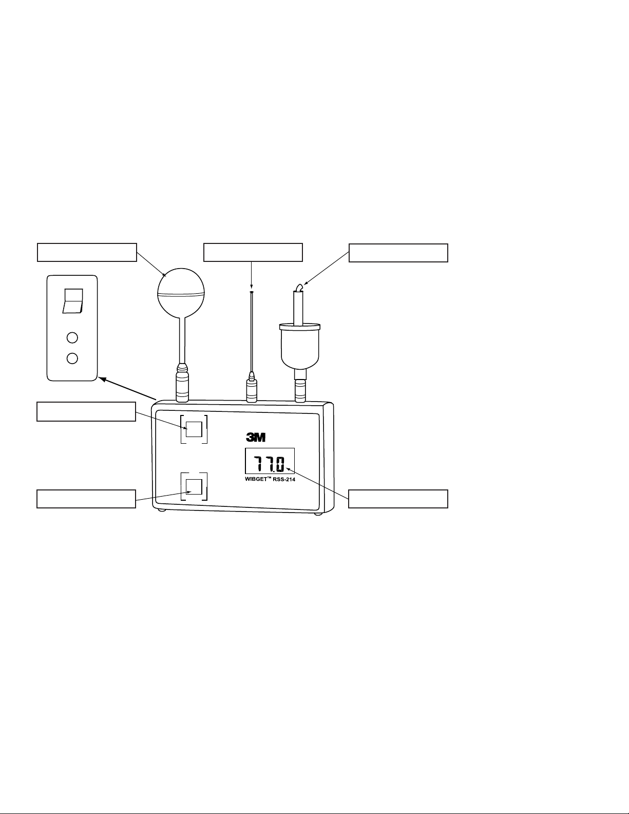
Touche des fonctions (Function)
Capteur du globe Capteur du réservoir sec
Capteur du réservoir humide
Affichage ACLTouche de sélection (Select)
ON
OFF
Analog
Output
0-1V
Charger
12vdc
Important
Avant d‘utiliser cet instrument, chaque utilisateur doit lire et comprendre les présentes Directives d‘utilisation. Conserver ces Directives d‘utilisation à
titre de référence.
Description générale
Les présentes Directives d’utilisation s’appliquent au moniteur de stress thermique RSS-214 WIBGET de 3M™. Cet instrument est un thermomètre globe mouillé portatif
doté d’un microprocesseur, conçu pour mesurer certains facteurs environnementaux qui peuvent contribuer au stress thermique. Un microprocesseur interne commande
les indications et les réponses aux signaux reçus par les capteurs fixés sur le dessus de l’appareil. Lorsqu’il est sous tension, il surveille de façon continue l’air ambiant.
Le moniteur WIBGET est alimenté par une pile rechargeable à hydrure métallique de nickel (NiMh) de 9 volts ou une pile alcaline non rechargeable de 9 volts. Il est conçu
pour être intrinsèquement sécuritaire lorsqu’il est alimenté par des piles. Le moniteur WIBGET est homologué intrinsèquement sécuritaire par la CSA pour les endroits
dangereux de classe 1, division I, groupes A, B, C et D.
Les composants du moniteur WIBGET sont montés dans un boîtier en plastique de 12,2 x 6,9 x 3,6 cm - haut./larg./prof. (3,75 x 6,2 x 1,75 po - haut./larg./prof.) (Fig. 1).
L’écran (ACL) et les touches de fonctions (FUNCTION) et de sélections (SELECT) se trouvent sur la face avant de l’appareil. L’interrupteur On/Off, la sortie des données
analogiques et la prise du chargeur se trouvent sur le côté gauche de l’appareil. Sur le dessus de l’appareil se trouvent les broches de connecteur des capteurs du globe, du
réservoir sec et du réservoir humide. Une étiquette sur laquelle figurent l’information en matière de sécurité intrinsèque et le numéro de série se trouve à l’arrière de l’appareil.
Fig. 1
17
Page 18

SPÉCIFICATIONS
Taille 15,8 x 9,5 x 4,5 cm / 6,2 x 3,75 x 1,75 po
Hauteur avec capteurs – 21,6 cm / 8,5 po
Poids 350 g (12 oz)
Affichage ACL à lecture directe
Lecture · Température intérieure du thermomètre à globe mouillé (IN WBGT)
· Température extérieure du thermomètre à globe mouillé (OUT WBGT)
· Réservoir humide (WB)
· Réservoir sec (DB)
· Température du globe (GT)
Calculs des valeurs WBGT · WBGT (extérieure) = 0,7 WB + 0,2 GT + 0,1 DB
· WBGT (intérieur) = 0,7 WB + 0,3 GT
(WB = réservoir humide; GT = température équivalente du globe Vernon; DB = réservoir sec)
Résolution de l’affichage 0,1 °C/0,1 °F
Intervalles gradués 25 °C (77 °F); 45 °C (113 °F); 60 °C (140 °F)
Réponse · Électronique < 3 secondes (à condition que les capteurs soient acclimatés)
· Capteurs (90 % d’exactitude) <2,2 minutes
· Capteurs (95 % d’exactitude) <4,5 minutes
Capteurs · Température du globe (GT) – la construction présente des caractéristiques identiques au globe Vernon de 6 po
· Réservoir sec (DB) – Température de l’air ambiant
· Réservoir humide (WB) – Capteur recouvert d’une mèche avec un réservoir mouillé avec de l’eau
désionisée ou distillée
Sécurité intrinsèque* CSA – Norme C22.2, nº 157-M1987, EXIA LR84375
Piles/sources d’énergie approuvées · Pile NiMh rechargeable de 9 volts (Varta™ V7/8H)
· Pile alcaline non rechargeable de 9 volts (Duracell
®
MN1604 ou Eveready® 522)
· Fonctionnement continu sur un bloc d’alimentation fourni par 3M (adaptateur c.a.)
Durée utile des piles Environ 17 heures – fonctionnement continu
Temps de recharge des piles (NiMh) Environ 14 heures
Plage des températures de fonctionnement De 0 à 65 °C (de 32 à 149 °F)
Température d’entreposage de l’instrument De -25 à 65 °C (de -13 à 140 °F)
Exactitude +/-0,4 °C (+/-0,7 °F) de la température réelle à 25,0 °C, 45°C et 60,0 °C (77,0 °F, 113 °F, 140,0 °F) à la
vitesse de l’air = 180 pi/min au minimum.
Sortie analogique/d’enregistreur 10mV/°C ± 1mV
Garantie 1 an (voir la section GARANTIE)
Journal de données (optionnel)
Journal de données Journal de données supplémentaire/accessoire de port RS232C optionnels
Mémoire Non volatile
Stockage d’enregistrement des données 511 enregistrements
Sortie d’enregistrement des données Numéro d’enregistrement, date, heure, WB, DB, GT, In-WBGT, Out-WBGT
Intervalle d’enregistrement des données Manuellement ou à des intervalles présélectionnés de 0,5, 1, 2, 5, 6, 10, 20 ou 30 minutes
* Les appareils RSS-214 et RSS-214DL sont intrinsèquement sécuritaires seulement lorsqu’ils sont utilisés avec les capteurs DB, WB et GT.
Varta est une marque de commerce de Spectrum Brands. Duracell est une marque de commerce déposée de Proctor & Gamble. Eveready est une marque de commerce déposée d’Eveready.
18
Page 19

THERMOMÈTRE GLOBE MOUILLÉ (WBGT)
Selon l’American Conference of Governmental Industrial Hygienists (ACGIH), la température adiabatique du thermomètre à globe mouillé (WBGT) peut s’avérer un indice
utile de premier ordre de la contribution environnementale au stress thermique. Elle est influencée par la température de l’air, la chaleur rayonnante et l’humidité. L’indice
WBGT correspond à la somme pondérée des températures du RÉSERVOIR SEC, du RÉSERVOIR HUMIDE et du GLOBE VERNON.
• Température du réservoir sec (DB) – procure une mesure de la « température ambiante ».
• Température adiabatique du thermomètre mouillé (WB) – procure une mesure du refroidissement par évaporation, incluant les effets de la vitesse de l’air et de
l’humidité. WB est toujours inférieure à DB.
• Température mesurée par thermomètre globe (GT) VERNON (noir, 6 po) – procure une mesure de la charge thermique rayonnante, incluant les effets de la vitesse de l’air.
Remarque : Le mini-globe du moniteur de stress thermique 3M
™
est l’équivalent du globe Vernon; le mini-globe procure la gt, où gt = 2/3 GT + 1/3 DB.
Les températures susmentionnées (GT, WB, DB) sont additionnées à l’indice WBGT généré comme suit :
OÙ GT = GLOBE VERNON DE 6 PO
OÙ gt = MINI-GLOBE DE 1,63 PO
Avec insolation directe
WBGT
= 0,7 WB + 0,2 GT + 0,1 DB = 0,7 WB + 0,3 gt
out
Sans insolation directe
WBGT
Remarque :
= 0,7 WB + 0,3 GT = 0,7 WB + 0,45 gt – 0,15 DB
in
Pour en savoir davantage sur la lecture de l’indice WBGT dans l’appréciation du stress thermique et de la contrainte thermique lors de l’évaluation du risque sur la
santé et de la sécurité au travail, la valeur limite d’exposition (VLE) au stress thermique de l’American Conference of Governmental Industrial Hygienists doit servir de référence.
INSTALLATION
Installation du capteur
Retirer le moniteur WIBGET et son réservoir sec, son réservoir humide et ses capteurs de globe de l’étui de transport. En tenant tour à tour chaque capteur par la prise de
connecteur, l’aligner verticalement et transversalement avec son récipient (comme il est indiqué sur le dessus de l’appareil), puis le pousser fermement en place. Un « clic »
sonore indique un engagement complet.
AVERTISSEMENT
Ne pas tordre les capteurs une fois que ceux-ci sont insérés dans l’unité principale. Cela risque d’endommager le capteur ou son connecteur.
Préparation du réservoir humide
Le capteur du réservoir humide requiert une attention vigilante pour aider à maintenir l’exactitude. La mèche doit être remplacée au premier signe de décoloration, de
rigidité ou de d’humectation insuffisante (voir la section ENTRETIEN). Remplir le réservoir et humidifier la mèche avec de l’eau distillée (ou déminéralisée). Une bouteille
et un déminéraliseur sont inclus avec l’instrument. Le réservoir humide peut être rempli sans affecter la lecture de l’instrument en ajoutant de l’eau à la température
ambiante à l’éponge (et non pas à la mèche). Un remplissage est normalement nécessaire à tous les jours. Des conditions d’humectation insuffisante, de température
élevée ou de vitesse de l’air élevée peuvent nécessiter des remplissages plus fréquents.
AVERTISSEMENT
Pour aider à maintenir l’exactitude du capteur, la mèche du réservoir humide doit rester humide pendant le fonctionnement de l’instrument.
Emplacement et environnement
Pour une exactitude optimale, les capteurs doivent être positionnés dans un espace ouvert et à environ un à deux mètres (de trois à six pieds) du plancher ou du sol dans la
zone de travail. Lorsque la charge rayonnante est élevée {GT = DB + 20 °C (68 °F)}, il faut apporter une attention particulière au blindage du capteur du réservoir sec.
Remarque :
Pour des renseignements et des directives supplémentaires sur l’appréciation du stress thermique en milieu de travail, se reporter à la VLE au stress
thermique de l’American Conference of Governmental Industrial Hygienists.
AVERTISSEMENT
Conserver tous les connecteurs propres et secs. Si un connecteur devient humide, il doit être séché à fond avant l’utilisation de l’instrument. L’état des compartiments des
capteurs peut être vérifié en retirant tous les capteurs, en mettant l’appareil sous tension, puis en examinant si toutes les fonctions indiquent 0,0 ± 0,3 °C or 32,0 ± 0,°F.
Si les lectures sont différentes, alors ne pas utiliser l’instrument jusqu’à ce que la cause soit déterminée et corrigée.
Ne pas exposer le réservoir sec à des températures supérieures à 65 °C (150 °F). Cela risque d’endommager l’unité principale. Pour surveiller les environnements dont la
température est supérieure à 65 °C (150 °F), utiliser un accessoire doté d’un capteur à distance et déplacer l’unité principale dans un endroit plus frais.
19
Page 20

DIRECTIVES D‘UTILISATION
I N O U T D B W B G T R H %
L O
B AT
° F
° C
Les directives suivantes sont destinées à l’utilisation du moniteur de stress thermique RSS-214 WIBGET
complètes et ne remplacent pas les politiques et procédures de chaque établissement.
MISE EN GARDE
Ce moniteur aide à mesurer certains facteurs environnementaux qui peuvent contribuer au stress thermique. Une mauvaise utilisation peut provoquer des
problèmes de santé ou la mort. Pour tout renseignement sur l‘utilisation adéquate de ce produit, consulter son superviseur, lire les Directives d‘utilisation ou
communiquer, au Canada, avec le Service technique au 1-800-267-4414.
Chaque utilisateur de ce matériel doit lire et comprendre les présentes Directives d‘utilisation. L‘utilisation de ce matériel par des personnes qui n’ont pas reçu la
formation nécessaire ou qui n’ont pas les qualifications requises, ou l’utilisation non conforme aux présentes Directives d’utilisation, peut nuire au bon fonctionnement du
produit et provoquer des problèmes de santé ou la mort.
N’utiliser ces capteurs et cet instrument que pour la surveillance des facteurs environnementaux pour lesquels ils sont conçus. Tout manquement à ces directives peut
nuire au bon fonctionnement du produit et provoquer des problèmes de santé ou la mort. Pour tout renseignement sur l‘utilisation adéquate de ce produit, consulter
son superviseur, lire les Directives d‘utilisation ou communiquer, au Canada, avec le Service technique au 1-800-267-4414.
S‘il y a des doutes concernant l‘utilisation du matériel dans le cadre de votre travail, consultez un hygiéniste industriel ou communiquez avec le service technique du
Service de santé au travail et de sécurité environnementale de 3M au 1-800-243-4630 et, au Canada, communiquer avec le Service technique au 1-800-267-4414.
Mise sous tension / hors tension
Faire pivoter l’interrupteur ON/OFF (situé sur le côté supérieur gauche de l’appareil) en position ON. Pour mettre l’appareil hors tension, faire pivoter cet interrupteur en
position OFF.
Autodiagnostics
MISE EN GARDE
Chaque fois que l’appareil est mis sous tension, ce dernier effectue un auto-test. En cas d’échec de l’auto-test ou d’affichage d’un code d’erreur, ne pas
utiliser cet appareil. Cela risque de nuire au bon fonctionnement du produit et provoquer des problèmes de santé ou la mort.
Chaque fois que l’appareil est mis sous tension, un autodiagnostic de l’appareil est effectué. Tous les segments de l’affichage ACL sont alors activés (Fig. 2). Après
cinq secondes, l’affichage indiquera « OUT WBGT » en °C. Si l’affichage ACL demeure vierge (ou s’estompe), qu’un segment ne s’active pas, qu’un un code « E # »
s’affiche (même temporairement) ou, si l’indicateur « LO BAT » s’affiche au cours du fonctionnement,
message ou de l’état soit déterminée et corrigée.
™
de 3M™. Elles ne doivent pas être considérées comme étant
ne pas utiliser l’instrument jusqu’à ce que la cause du
Fig. 2
Mode de surveillance
Appuyer sur la touche SELECT pour passer d’une échelle de température à une autre (°C/°F).
Appuyer sur la touche VIEW pour parcourir la lecture individuelle des capteurs (WB, DB, GT) et la lecture de l’indice WBGT. Appuyer sur la touche VIEW jusqu’à ce que la
lecture souhaitée apparaisse.
Sortie analogique/d’enregistreur (mode de surveillance seulement)
Un signal analogique proportionnel à la valeur d’affichage [0 mV à 0,0 °C (32,0 °F) à 1000 mV à 100,0 °C (212,0 °F)] est émis par l’entremise d’une petite prise
pour écouteurs située sur le côté inférieur gauche du moniteur. Un enregistreur à bande déroulante compatible peut y être branché. Cet enregistreur doit posséder une
impédance d’entrée minimale de 1 000 ohms. L’erreur est inférieure à 0,1 °C par rapport à la valeur affichée.
20
Page 21

ENREGISTREMENT DES DONNÉES (optionnel)
FUNCTION
VIEW
OUT WBGT
start
SELECT
MONITOR / log
°C/°F
time base
°F
ON
OFF
Analog
Output
0-1V
Charger
12vdc
Touche des fonctions (Function)
Capteur du globe Capteur du réservoir sec
Capteur du réservoir humide
Affichage ACLTouche de sélection (Select)
MISE EN GARDE
Le port de sortie de données en série RSS-214DL RS 232 ne doit être utilisé que dans un endroit non dangereux. L’utilisation du port de sortie des données n’est pas
une opération intrinsèquement sécuritaire. Tout manquement à ces directives peut provoquer des problèmes de santé ou la mort.
Le journal de données/accessoire de port de sortie de données en série RS232C est une option qui offre des fonctions de stockage non volatile de données numériques et
de communications. Jusqu’à 511 jeux de données (numéro d’enregistrement, heure, date et cinq fonctions de surveillance) peuvent être enregistrés et téléchargés sur un
ordinateur. Les données enregistrées ne sont pas perdues en cas d’arrêt de l’appareil, de retrait des capteurs, de faiblesse de la pile ou de saturation de la mémoire.
Fig. 3
Configuration et affichage du calendrier/de l’horloge
Tout en mettant l’appareil sous tension, appuyer sur la touche SELECT jusqu’à ce que l’autodiagnostic soit terminé et que l’année soit affichée (l’an 2000 est affichée sous
le format « 00 ») Pour régler un paramètre, appuyer sur la touche VIEW et, pour entrer une valeur, appuyer sur SELECT.
Dès qu’un paramètre est entré, le paramètre suivant s’affiche. La séquence d’affichage est la suivante :
Année, mois, date, jour de la semaine (1 = dimanche, 7 = samedi), heure (horloge de 24 heures), minutes. Les secondes sont remises à zéro si les paramètres de l’horloge
sont modifiés, mais pas si l’horloge n’est qu’affichée. L’horloge fonctionne de façon continue lorsque l’appareil est éteint et offre la même sécurité ainsi que la même durée
utile que les données du journal.
Mode d’enregistrement
Pour passer au mode d’enregistrement des données actuelles et des données précédentes déjà en mémoire :
1. Après la mise sous tension de l’instrument, appuyer sur la touche VIEW et la maintenir, puis appuyer sur SELECT et relâcher les deux touches. L’affichage indique
« AP ». (APPEND).
2. Pour joindre (ajouter) des données à celles qui sont déjà en mémoire, appuyer de nouveau sur SELECT. L’intervalle de temps depuis la session d’enregistrement des
données précédente s’affiche.
3. Au besoin, l’intervalle de temps peut alors être modifié en appuyant sur la touche VIEW (time base) pour sélectionner un intervalle de temps différent. Les intervalles de
temps disponibles sont 0,5; 1,0; 2,0; 5,0; 6,0; 10,0; 20,0 et 30,0 minutes.
4. Appuyer de nouveau sur SELECT pour reprendre l’enregistrement des données sans effacer les enregistrements précédents stockés en mémoire.
Pour passer au mode d’enregistrement et effacer toutes les sessions d’enregistrement des données précédentes en mémoire :
1. Appuyer sur la touche VIEW et la maintenir, puis appuyer sur SELECT et relâcher les deux touches. L’affichage indique « AP ». (APPEND).
2. Choisir un intervalle de temps en appuyant sur la touche VIEW (time base) jusqu’à ce que l’intervalle de temps souhaité apparaisse. Se reporter à l’étape 3 ci-dessus
pour connaître les intervalles de temps disponibles.
3. Appuyer sur SELECT pour commencer à journaliser les données et effacer toutes les sessions d’enregistrement des données précédentes stockées en mémoire.
Remarque :
Le moniteur WIBGET se remet automatiquement en mode de surveillance lorsque la mémoire est pleine.
21
Page 22

Enregistrement à la demande
La sélection de la touche SELECT permet en tout temps durant l’enregistrement des données d’ajouter immédiatement en mémoire un jeu de données différent des jeux
de données enregistrés en fonction de l’intervalle de temps prédéfini. Cette fonction est pratique si un événement inhabituel survient à un moment différent des intervalles
de temps prédéfinis. Par exemple, si l’enregistrement des données est effectuée à toutes les 30 minutes et qu’un événement inhabituel survient 14 minutes après le
dernier enregistrement, la sélection de la touche SELECT enregistre cet événement en mémoire 14 minutes après l’enregistrement de la dernière tranche de 30 minutes,
sans affecter l’intervalle de temps prédéfini de 30 minutes.
Pour effectuer un enregistrement des données à la demande seulement :
1. Appuyer sur la touche VIEW et la maintenir, puis appuyer sur SELECT et relâcher les deux touches. L’affichage indique « AP ». (APPEND).
2. Appuyer sur la touche VIEW jusqu’à ce que l’affiche indique « 0 ».
3. La sélection la touche SELECT permet en tout temps d’ajouter immédiatement un jeu de données en mémoire avec une indication de l’heure. Comme aucun intervalle
de temps n’est sélectionné, l’enregistrement des données n’est effectué que lorsque la touche SELECT est sélectionnée.
Affichage en cours d’enregistrement
Pour afficher une fonction au cours de l’enregistrement des données, appuyer sur la touche VIEW et la maintenir afin d’afficher une fonction en cours (indice OUT WBGT,
WB, DB, etc.). En relâchant la touche VIEW et en appuyant sur cette dernière, chaque fonction peut être affichée.
Arrêt d’enregistrement des données
Simplement mettre l’appareil WIBGET hors tension au moyen de l’interrupteur ON/OFF. Toutes les données en mémoire restent stockées en mémoire.
Arrêt du mode d’enregistrement des données et retour au mode de surveillance
Appuyer sur la touche VIEW et la maintenir, puis appuyer sur SELECT et relâcher les deux touches. L’affichage est alors en mode de surveillance et indique OUT WBGT.
D’autre part, la sélection successive de la touche VIEW affiche tour à tour chaque fonction (indice OUT WBGT, WB, DB, etc.).
TÉLÉCHARGEMENT DES DONNÉES
Configuration nécessaire
La configuration minimum suivante est requise pour installer, configurer et utiliser le logiciel du moniteur de stress thermique WIBGET™ de 3M™. Un ordinateur personnel
ou un ordinateur portatif exploité par Windows 98, 2000 ou XP et doté d’un port de communication RS-232 disponible. Remarque : Un adaptateur DB-9 à DB-25 peut
être requis pour brancher le câble RS-232 au port série de l’ordinateur.
Installation du logiciel du moniteur de stress thermique WIBGET
1. Fermer tous les programmes en cours d’exécution dans Windows.
2. Insérer le CD du logiciel du moniteur de stress thermique WIBGET dans le lecteur de CD-ROM de l’ordinateur personnel ou de l’ordinateur portatif.
3. Dans Microsoft Explorer (ou Mon poste de travail), double-cliquer sur le lecteur de CD approprié (souvent le lecteur D:) et repérer le fichier Setup.exe.
4. Double-cliquer sur le fichier Setup.exe ou sur l’icône pour démarrer l’installation.
5. Suivre les directives des écrans de menu pour initialiser le programme logiciel du moniteur de stress thermique. Il est recommandé de conserver les noms de fichier et
de dossier par défaut.
Téléchargement des données
Les données peuvent être téléchargées sur un ordinateur pendant que le moniteur WIBGET effectue un enregistrement sans perturber l’une ou l’autre de ces activités. Un
programme piloté par menus inclus sur le CD offre la possibilité de manipuler et de stocker les données à partir d’un ordinateur. Remarque : Les données de température
du WIBGET sont enregistrées en degrés Celsius. Si une lecture en degrés Fahrenheit est souhaitée, appuyer sur SELECT juste avant de télécharger les données sur
l’ordinateur. Pour télécharger des données :
1. Mettre le moniteur WIBGET sous tension.
2. Raccorder le moniteur WIBGET à l’ordinateur au moyen du câble d’interface série inclus.
3. Ouvrir le programme logiciel du moniteur de stress thermique WIBGET.
4. Sur l’onglet File, sélectionner Read WIBGET.
5. Un menu de téléchargement s’affiche. Sélectionner l’élément Download du menu.
6. Le moniteur WIBGET commence alors à transmettre les données Lorsque le téléchargement est terminé, sortir du menu de téléchargement. Un tableau de données
s’affiche à l’écran (semblable au Tableau 1 ci-dessous).
7. Utiliser les autres fonctions de menu pour analyser, enregistrer et imprimer les données.
22
Page 23

RSS-214 WIBGET DATA File: :\WBGT\DATA\SAMPLE.WBG
Upload Date: 2006/09/17 Time: 13.46
Record Number Time
(hh:mm)
Test: 2006/09/17
Wet Bulb Dry
Bulb
Globe WBGT
In Out
Location: Floor CLO Value: 1.0 TWM: IN - 1 hour
2 11:12 16.7 21.6 38.0 23.1 21.4 0.0
3 11:17 19.4 27.4 49.8 28.5 26.3 0.0
4 11:22 19.6 27.7 51.9 29.3 26.9 0.0
5 11:27 19.9 27.8 52.3 29.6 27.2 0.0
6 11:32 19.6 27.3 51.4 29.1 26.7 0.0
7 11:37 19.6 27.6 51.4 29.2 26.8 0.0
8 11:42 19.6 27.5 51.3 29.1 26.8 28.5
9 11:47 19.6 27.5 50.8 28.9 26.6 29.0
10 11:52 19.5 27.3 50.9 28.9 26.5 29.0
11 11:57 19.4 27.2 50.6 28.8 26.4 29.0
12 12:02 19.3 27.1
13 12.07
14 12:12
19.5 27.2 51.2 29.0 26.6 28.9
19.5 27.4 51.2 29.0 26.6 28.9
50.5 28.7 26.3 28.9
15 12:17 19.3 27.3 51.2 20.9 26.5 28.8
16 12:22 19.5 27.3 50.8 20.9 26.5 28.9
17 12.27 19.5 27.3 51.0 28.9 26.6 28.9
18 12:32 19.4 27.6 51.2 28:9 26.6 28.9
19 12:37 19.4 27.4 50.7 28.8 26.4 28.9
20 12:42
21 12:47 19.4 97.4
19:6 27.7 51.3 29.1 26.7 28.9
51.1 28.9 26.5 28.9
22 12:52 19.5 27.4 51.2 29.0 26.6 29.0
23 12:57 19.5 27.5 50.9 29.9 26.5 29.0
24 13:02 19.6 27.6 51.2 29.0 26.7 29.0
25 13:07
26 13:12
27 13:17
28 13:22
19.6 27.8 51.5 29.2 26.8 29.0
19.6 28.0 51.3 29.1 26.8 0.0
19.5 27.8 51.5 29.1 26.7 0.0
10.7 27.9 51.7 29.3 26.9 0.0
29 13:27 19.4 27.3 51.4 29.0 26.6
30 13:32 19.3 27.3 51.2 28.9 26.5
31 13:37 19.4 27.5 51.4 29.0 26.6
Tableau 1 (sortie sur imprimante/écran typique)
Desc: Sample
Metabolic - TWM
TWM RATE
0.0
0.0
0.0
23
Page 24

ENTRETIEN
MISE EN GARDE
Ne jamais modifier cet instrument. La substitution de composants risque de compromettre la sécurité intrinsèque. Cela risque de nuire au bon fonctionnement du produit
et provoquer des problèmes de santé ou la mort.
Ne réparer l’instrument et n’en remplacer les composants qu‘avec des composants 3M approuvés pour l‘appareil.
Tout manquement à ces directives peut nuire au
bon fonctionnement du produit et provoquer des problèmes de santé ou la mort.
Réservoir humide
L’utilisation du réservoir humide avec une mèche abîmée (c.-à-d. décolorée, rigide ou non humectée) risque de fausser la lecture (élevée).
Remplacement des mèches
Pour remplacer une mèche abîmée, la retirer en tirant vers le haut avec son éponge par-dessus le capteur. Glisser une nouvelle mèche 3M compatible appropriée pardessus le capteur de sorte qu’elle soit bien ajustée par-dessus l’extrémité et qu’elle atteigne le fond du réservoir. Afin de prévenir les dégâts d’eau, une éponge 3M ajustée
doit être installée par-dessus le capteur et positionnée dans le bec du réservoir. L’humectation de l’éponge et de la mèche facilite leur retrait et leur remplacement.
Traitement de l’eau
Pour une exactitude et une durée utile optimales de la mèche, de l’eau distillée doit être utilisée (disponible dans la plupart des pharmacies). De l’eau potable déminéralisée
peut également être utilisée. Veiller à suivre attentivement les directives incluses avec le déminéraliseur.
Nettoyage
AVERTISSEMENT
Éviter d’utiliser des agents de nettoyage forts, des abrasifs et d’autres solvants organiques. De tels produits peuvent égratigner les surfaces de façon permanente et
endommager la fenêtre d’affichage, les étiquettes ou le boîtier du moniteur.
Pour nettoyer les surfaces externes, utiliser un linge/chiffon doux ainsi qu’un mélange d’eau chaude et de détergent doux.
Entreposage
Retirer chaque capteur en tirant vers le haut (NE PAS LE TORDRE) sur le collet de son connecteur. Vider le réservoir humide et essorer l’excès d’eau de son éponge. Ranger
tous les articles dans l’étui de transport, comme il se doit.
PILE
MISE EN GARDE
Ne remplacer la pile que dans un endroit non dangereux. Le remplacement de la pile n’est pas une opération intrinsèquement sécuritaire. N’utiliser que des piles
approuvées. Tout manquement à ces directives peut provoquer des problèmes de santé ou la mort.
Ne recharger l’instrument que dans des zones sans danger à l’aide d’un bloc d’alimentation 3M (adaptateur c.a.). Le chargement et le fonctionnement de piles au
moyen d’un adaptateur c.a. ne sont pas des opérations intrinsèquement sécuritaires. Ne pas tenter de recharger des piles alcalines. Cela risque de nuire au bon
fonctionnement du produit et provoquer des problèmes de santé ou la mort.
AVERTISSEMENT
Insérer la pile selon la polarité appropriée. La polarité est indiquée à l’intérieur du compartiment de la pile.
Cet instrument peut contenir une pile à hydrure métallique de nickel (NiMh). Mettre la pile au rebut conformément aux règlements locaux.
Le moniteur WIBGET est alimenté par une pile NiMh rechargeable de 9 volts (8,4 v) et comprend un bloc d’alimentation externe. De plus, le moniteur WIBGET peut
fonctionner au moyen d’une pile alcaline non rechargeable de 9 volts ou du bloc d’alimentation (adaptateur a.c.).
Chargement
Lorsque la pile est presque complètement déchargée, « LOBAT » s’affiche dans le coin supérieur droit de l’écran. Pour un fonctionnement continu ou simplement recharger
la pile, brancher le bloc d’alimentation dans sa prise (12 V c.c.) située dans le coin inférieur gauche du moniteur. Le chargement requiert 12 heures au minimum. Même si
les piles NiMh peuvent être rechargées de nombreuses fois, elles finissent tôt ou tard par se dégrader et doivent alors être remplacées.
Remplacement
Faire pivoter l’interrupteur à « OFF », dévisser les quatre vis du compartiment arrière et ouvrir l’instrument. Prendre note de l’emplacement de la pile, puis la remplacer.
Réinstaller le compartiment arrière en revissant les vis.
ÉTALONNAGE
L’unité principale du moniteur WIBGET et les trois capteurs peuvent être retournés à 3M pour fins d’étalonnage selon les normes NIST. Un CERTIFICAT D’ÉTALONNAGE
D’INSTRUMENT n’est émis que si l’étalonnage de l’unité principale de l’appareil WIBGET et des trois capteurs est réussi. Une certification identifiable et les données avant/
après sont également disponibles moyennant des frais supplémentaires. L’étalonnage annuel du moniteur WIBGET est recommandé.
24
Page 25

DÉPANNAGE
Consulter le tableau ci-dessous pour connaître les causes probables de problèmes et les mesures correctives à apporter. Pour de l’aide supplémentaire, au Canada,
communiquer avec le Service technique au 1-800-267-4414.
Anomalies Cause éventuelle Solution possible
L’appareil ne répond pas lorsque son interrupteur est
en position « ON ».
La pile ne dure pas assez longtemps. Faiblesse de la pile/défectuosité du bloc
Faiblesse de la pile/défectuosité du bloc
d’alimentation
Remplacer la pile.
Remplacer la pile.
d’alimentation
Lecture très élevée Le connecteur est humide. Rincer le connecteur avec de l’alcool isopropylique et le faire sécher.
Le moniteur WIBGET transmet les données vers un
ordinateur, mais ce dernier ne les reçoit pas.
Le paramètre nº 4 de l’interrupteur interne
RSS-214 est incorrect
L’ordinateur génère des résultats insensés. Le paramètre nº 1 de l’interrupteur interne
RSS-214 est incorrect.
Verrouillage de l’ordinateur Le paramètre nº 3 de l’interrupteur interne
Réinitialiser l’interrupteur nº 4, puis redémarrer l’ordinateur
pour réinitialiser le port de communication.
Définir à une position différente (le débit de transmission de
l’interrupteur est de 300 ou de 1 200).
Définir à une position différente.
RSS-214 est incorrect.
Si un code « E » s’affiche (même temporairement) durant LA MISE SOUS TENSION OU LE L’AUTODIAGNOSTIC, se reporter au tableau suivant :
Code affiché Cause éventuelle Solution possible
E1, E2, E3
E4, E5
Défaillance d’un composant Retourner pour fins de réparation.
Sortie analogique hors étalonnage Régler Trim R à 250 mv à 25,0 °C.
E6GT, E6WB, E6DB Défectuosité spécifique du capteur Brancher, nettoyer ou remplacer les capteurs défectueux.
E7, E8 Défaillance de la mémoire ou faiblesse de la pile Retourner pour fins de réparation ou recharger/remplacer la pile.
PRODUITS, ACCESSOIRES ET PIÈCES
MISE EN GARDE
Ne jamais modifier cet instrument. La substitution de composants risque de compromettre la sécurité intrinsèque. Cela risque de nuire au bon fonctionnement du produit
et provoquer des problèmes de santé ou la mort.
Ne réparer l’instrument et n’en remplacer les composants qu‘avec des composants 3M approuvés pour l‘appareil.
Tout manquement à ces directives peut nuire au
bon fonctionnement du produit et provoquer des problèmes de santé ou la mort.
Moniteurs de stress thermique WIBGET
Pièce n° Description
RSS-214 Moniteur de stress thermique WIBGET™ de 3M
RSS-214DL
Moniteur de stress thermique WIBGET™ de 3M avec enregistrement des données
Pièces de rechange et accessoires
Pièce n° Description
323-1402 Capteur de réservoir sec de 3M
323-1203 Capteur de réservoir humide de 3M
™
™
323-5020 Trousse de réservoir humide de 3M™ (contient un déminéraliseur, 6 mèches et 2 éponges)
323-1003 Capteur de globe de 3M
323-5025 Pile NiMh de 9 volts et bloc d’alimentation de 3M
227-0500 Pile NiMh de 9 volts de 3M
229-0102 Bouteille d’eau de 3M
™
™
™
™
323-2220 Trousse de capteur personnel de 3M™ (avec fixation pour casque de protection)
323-2200 Câble d’assemblage de capteur de 10 pi de 3M
323-2201 Câble d’assemblage de capteur de 20 pi de 3M
323-2202 Câble d’assemblage de capteur de 50 pi de 3M
323-2203 Câble d’assemblage de capteur à distance de 100 pi de 3M
323-2202wp Câble d’assemblage de capteur à distance étanche de 50 pi de 3M
323-2203wp Câble d’assemblage de capteur à distance étanche de 100 pi de 3M
™
™
™
™
™
™
25
Page 26

AVIS IMPORANT
GARANTIE
3M garantit que ses moniteurs de stress thermique RSS-214 et RSS-214DL sont exempts de défauts de matériau et de fabrication dans des conditions d’utilisation
normales pendant 1 an à compter de la date de fabrication.
Cette garantie est annulée si le moniteur de stress thermique 3M est endommagé en raison d‘un accident, d‘une mauvaise utilisation, d‘une négligence, d‘un entretien
inadéquat ou d‘autres causes non attribuables à un défaut de matériau ou de fabrication. Cette garantie exclut les pièces à remplacer, comme les mèches, les éponges, le
déminéraliseur et les piles, dont le remplacement fait partie de l‘entretien périodique. Toute garantie implicite résultant de la vente des moniteurs de stress thermique 3M, y
compris, mais sans s‘y limiter, toute garantie de qualité marchande et d‘adaptation à un usage particulier, est limitée aux durées indiquées ci-dessus. 3M ne saurait être tenue
responsable de la perte d‘utilisation d‘un de ses produits ou des coûts, dépenses ou dommages fortuits ou conséquents encourus par l‘acheteur ou tout autre utilisateur.
RECOURS
Si le moniteur de stress thermique 3M tombe en panne dans des conditions d‘utilisation normales sans que l‘acheteur ou un autre utilisateur n‘en soit la cause pendant
la période de garantie, retourner le détecteur ou moniteur à un centre de service autorisé en vertu de la garantie. Pour connaître l’emplacement des centres de service
autorisés 3M au Canada, communiquer avec le Service technique au 1-800-267-4414. Les réparations ou les remplacements seront effectués gratuitement. Chaque
appareil réparé est garanti pendant soixante (60) jours ou pendant la durée restante de la garantie d‘origine du matériel, selon la plus longue durée.
EXCLUSIONS DE LA GARANTIE :
LA GARANTIE QUI PRÉCÈDE EST EXCLUSIVE ET TIENT LIEU DE TOUTE GARANTIE EXPLICITE, IMPLICITE OU STATUAIRE, Y COMPRIS DE
TOUTE GARANTIE DE QUALITÉ MARCHANDE ET D‘ADAPTATION À UN USAGE PARTICULIER OU TOUTE AUTRE GARANTIE DE QUALITÉ.
LIMITATION DE LA RESPONSABILITÉ :
CE QUI PRÉCÈDE CONSTITUE LE SEUL ET UNIQUE RECOURS QUI TIENT LIEU DE TOUT AUTRE RECOURS POUVANT S‘APPLIQUER.
Toute réparation ou modification effectuée au matériel garanti sans l‘autorisation de 3M annule immédiatement la présente garantie.
RENSEIGNEMENTS SUPPLÉMENTAIRES
Aux États-Unis,
Internet : www.3M.com/OccSafety
Assistance technique : 1-800-243-4630
Pour les autres produits 3M :
contacter :
1-800-364-3577 or 1-651-737-6501
Au Canada, contacter :
Internet : www.3M.com/CA/OccSafety
Assistance technique : 1-800-267-4414
Pour les autres produits 3M :
1-800-364-3577
26
Page 27

3
FUNCTION
VIEW
OUT WBGT
start
SELECT
MONITOR / log
°C/°F
time base
°F
Monitor de estrés térmico WIBGET™ RSS-214
Instrucciones de uso
(Conserve estas Instrucciones de uso para referencia futura.)
ESPAÑOL
27
Page 28

ÍNDICE
INFORMACIÓN GENERAL DE SEGURIDAD 29
Uso 29
Lista de advertencias y precauciones 29
INSTRUCCIONES DE USO
Descripción general 30
ESPECIFICACIONES 31
WBGT
INSTALACIÓN 32
Instalación del sensor 32
Preparación del bulbo húmedo 32
Ubicación y ambiente 32
INSTRUCCIONES DE OPERACIÓN 33
Encendido/Apagado 33
Auto-diagnóstico 33
Modo de monitor 33
Salida análoga/a registrador (sólo modo de monitor) 33
REGISTRADOR DE DATOS (Opcional) 34
Programación y vista de calendario/reloj 34
Modo de registro 34
Registro en demanda 35
Vista durante el registro 35
Salida del registro de datos 35
32
Y LIMITACIONES 30
DESCARGA DE DATOS 35
Requerimientos del sistema 35
Instalación del programa para
el Monitor de estrés térmico WIBGET 35
Descarga de datos 36
MANTENIMIENTO 37
Bulbo húmedo 37
Reemplazo de la mecha 37
Tratamiento de agua 37
Limpieza 37
Almacenamiento 37
BATERÍA 37
Carga 37
Reemplazo 37
CALIBRACIÓN 37
LOCALIZACIÓN DE AVERÍAS 38
PRODUCTOS, ACCESORIOS Y PARTES 38
GARANTÍA 39
PARA MAYORES INFORMES 39
Salida del registro de datos y
regreso al modo de monitor 35
28
Page 29

INFORMACIÓN GENERAL DE SEGURIDAD
Uso
El Monitor de estrés térmico WIBGET™ 3M™ RSS-214 está diseñado para medir los factores ambientales que pueden contribuir al estrés térmico.
Lista de advertencias y precauciones incluidas en estas Instrucciones de uso
ADVERTENCIA
Este monitor ayuda a medir ciertos factores ambientales que puedenn contribuir al estrés térmico. El uso incorrecto puede ser causa de enfermedad o incluso la
muerte. Para su uso adecuado consulte a su supervisor o las Instrucciones de uso, o llame a 3M en EUA al 1-800-243-4630. En Canadá llame a Servicio Técnico al
1-800-267-4414. En México llame al 01-800-712-0646, o contacte a 3M en su país.
Antes de usar este respirador, cada usuario debe leer y comprender la información contenida en estas Instrucciones de uso. El uso de este equipo por personas no
capacitadas ni calificadas o su uso contrario a estas Instrucciones de uso puede afectar adversamente su funcionamiento y causar enfermedad o incluso la muerte.
Sólo utilice para monitorear factores ambientales para los cuales fueron diseñados los sensores y el equipo monitor. No hacerlo puede afectar adversamente el
desempeño del producto y ocasionar enfermedad o incluso la muerte. Para su uso adecuado consulte a su supervisor o las Instrucciones de uso, o llame a 3M en
EUA al 1-800-243-4630. En Canadá llame a Servicio Técnico al 1-800-267-4414. En México llame al 01-800-712-0646, o contacte a 3M en su país.
Cada vez que enciende el equipo, éste realiza un auto-prueba de verificación. No utilice el equipo, si falla la auto-prueba de verificación o si se despliega un código de
error. Hacerlo puede afectar adversamente el desempeño del producto y ocasionar enfermedad o incluso la muerte.
El puerto serial de salida de datos RSS-214DL RS 232 sólo debe utilizarse en un área no peligrosa. Usar el puerto de salida de datos no es una operación
intrínsicamente segura. No hacer lo indicado con anterioridad puede causar enfermedad o incluso la muerte.
Nunca altere ni modifique este equipo. La sustitución de los componentes puede dañar la seguridad intrínseca. Hacerlo puede afectar adversamente el desempeño del
producto y ocasionar enfermedad o incluso la muerte.
Sólo repare o reemplace las partes con los componentes 3M aprobados para este equipo.
No hacerlo puede afectar adversamente el desempeño del producto y
ocasionar enfermedad o incluso la muerte.
Sólo debe reemplazar la batería en un área segura. El reemplazo de la batería no es una operación intrínsecamente segura. Sólo use una batería aprobada. No hacerlo
puede causar enfermedad o incluso la muerte.
Sólo cargue el equipo en áreas seguras con un cargador para batería 3M (adaptador CA). Cargar y operar la batería con un adaptador CA no es una operación
intrínsecamente segura. No intente cargar las baterías alcalinas. Hacerlo puede afectar adversamente el desempeño del producto y ocasionar enfermedad o
incluso la muerte.
PRECAUCIÓN
No tuerza los sensores una vez que los haya insertado en el equipo base; hacerlo puede dañar el sensor o el conector de éste.
La mecha del bulbo debe permanecer húmeda durante la operación para mantener la exactitud del sensor.
Mantenga todos los conectores limpios y secos. Si un conector se moja, debe secarlo bien antes de usar el equipo. Puede probar la condición de los receptáculos de
sensor al quitar todos los sensores, encender el equipo y revisar que todas las funciones tengan la lectura de 0.0 ± 0.3°C ó 32.0 ± 0.5°F. Si las lecturas son distintas a
las mencionadas, no use el equipo hasta determinar y corregir la causa de la falla.
No exponga el bulbo seco a temperaturas mayores de 65 °C (150 °F), ya que puede dañar el equipo base. Para monitorear ambientes con temperaturas mayores de
65 °C (150 °F), use un accesorio de sensor remoto y reubique el equipo base en un área más fresca.
Evite el uso de materiales de limpieza fuertes, abrasivos y otros solventes orgánicos, ya que estos rayarán permanentemente las superficies y dañarán la ventana de la
pantalla, las etiquetas o la caja del monitor.
Inserte la batería de acuerdo con la polaridad correcta, marcada en el interior del compartimiento de batería.
Este equipo puede contener una batería de Níquel Metal Hidruro (NiMH). Elimine la batería de acuerdo con las regulaciones locales.
29
Page 30

INSTRUCCIONES DE USO Y LIMITACIONES
FUNCTION
VIEW
OUT WBGT
start
SELECT
MONITOR / log
°C/°F
time base
°F
Botón de función
Sensor de globo Sensor de bulbo seco
Sensor de bulbo húmedo
Pantalla LCDBotón de selección
ON
OFF
Analog
Output
0-1V
Charger
12vdc
Importante
Antes de usar este equipo, cada usuario debe leer y entender estas Instrucciones de uso. Conserve estas Instrucciones de uso para referencia futura.
Descripción general
Estas Instrucciones de uso aplican para el Monitor de estrés térmico WIBGET 3M™ RSS-214, termómetro de globo y bulbo húmedo con base en un microprocesador,
diseñado para medir ciertos factores ambientales que pueden contribuir al estrés térmico. Un microprocesador interno controla la indicación y respuesta a las señales
recibidas de los sensores montados en la parte superior del equipo, que al encenderse monitorea continuamente el aire del medio ambiente.
El monitor WIBGET es un equipo energizado con una batería recargable de níquel metal hidruro (NiMH) de 9 voltios o con una batería no recargable alcalina de 9 voltios. Es
intrínsicamente seguro cuando se energiza con estas baterías. El monitor WIBGET cuenta con la certificación de la Asociación Canadiense de Normas (CSA por sus siglas
en inglés) para seguridad intrínseca para Clase I, Div. I, Grupos A,B,C, y D de Locaciones peligrosas.
Los componentes del monitor WIBGET están ensamblados en una caja plástica de 9.5 cm (3.75 pulgs) de altura x 15.7 cm (6.2 pulgs) de ancho x 4.4 cm (1.75 pulgs) de
diámetro (Fig 1). En el frente del equipo se encuentra la pantalla (LCD) y los botones FUNCIÓN (FUNCTION) y SELECCIÓN (SELECT). En el lado izquierdo se encuentra el
interruptor de encendido/apagado (On/Off), la salida análoga y el enchufe para el cargador. En la parte superior se encuentran los broches para el conector del sensor para
los sensores de Globo (GT), Bulbo seco (DB) y Bulbo húmedo (WB). En la parte trasera está la etiqueta con la información sobre seguridad intrínseca y el número de serie.
Fig. 1
30
Page 31

ESPECIFICACIONES
Tamaño 6.2 x 3.75 x 1.75 (pulgadas), 15.8 x 9.5 x 4.5 (cm)
8.5 (pulgadas), 21.6 (cm) de altura con sensores
Peso 12 oz. (350g)
Impresión Lectura directa desde la pantalla LCD
Lecturas · Temperatura de globo y bulbo húmedo en interiores (IN WBGT)
· Temperatura de globo y bulbo húmedo en exteriores (OUT WBGT)
· Bulbo húmedo (WB)
· Bulbo seco (DB)
· Temperatura de globo (GT)
Cálculos de valor WBGT · WBGT (en exteriores) = 0.7 WB + 0.2 GT + 0.1DB
· WBGT (en interiores) = 0.7 WB + 0.3 GT
(WB = Bulbo húmedo; GT = Temperatura equivalente de globo de Vernon; DB = Bulbo seco)
Resolución de lectura 0.1 °C/0.1°F
Rangos calibrados 25 °C (77 °F); 45 °C (113 °F); 60 °C (140 °F)
Respuesta · Equipo eléctrico < 3 segundos (Los sensores incluidos están climatizados)
· Sensores (90% de exactitud) <2.2 minutos
· Sensores (95% de exactitud) <4.5 minutos
Sensores · Temperatura de globo (GT) – La construcción ofrece características idénticas a las del Globo de Vernon de 6"
· Bulbo seco (DB) – Temperatura de aire ambiente
· Bulbo húmedo (WB) – Sensor con mecha cubierta con depósito, húmedo con agua destilada o desionizada
Seguridad intrínseca* CSA – Norma C22.2 No. 157-M1987, EXIA LR84375
Baterías aprobadas/Fuente de energía · Batería NiMH recargable de 9 voltios (Varta™ V7/8H)
· Batería alcalina no recargable de 9 voltios (Duracell
®
MN1604 o Eveready® 522)
· Operación continua con cargador 3M incluido (adaptador CA)
Vida de la batería Aproximadamente 17 horas – operación continua
Tiempo de recarga de la batería (NiMH) Aproximadamente 14 horas
Rango de temperatura de operación 0 °C a 65 °C (32 °F a 149 °F)
Temperatura de almacenamiento del equipo -25 °C a 65 °C (-13 °F a 140 °F)
Exactitud +/-0.4 °C (+/-0.7 °F) de temperatura real a 25.0 °C, 45 °C y 60.0 °C (77.0 °F, 113 °F, 140.0 °F) @ velocidad del
aire = 180 pies/min mínimo.
Salida análoga/a registro 10mV/°C ± 1mV
Garantía 1 año (Consulte la sección de GARANTÍA)
Registrador de datos (Optional)
Registrador de datos Registrador opcional/Puerto RS232C
Memoria No volátil
Almacenamiento de registro de datos 511 registros
Salida de registro de datos Número de registro, fecha, hora, WB, DB, GT, En-WBGT, Salida-WBGT
Intervalo de registro de datos Manual o intervalos preseleccionados de 0.5, 1, 2, 5, 6, 10, 20 o 30 minutos
*Los monitores RSS-214 y RSS-214DL sólo son intrínsecamente seguros cuando se usan con sensores DB, WB y GT.
Varta es una marca registrada de Spectrum Brands. Duracell es una marca registrada de Procter & Gamble. Eveready es una marca registrada de Eveready.
31
Page 32

WBGT
De acuerdo con la Conferencia Americana de Higienistas Industriales Gubernamentales (ACGIH por sus siglas en inglés), la Temperatura de globo y bulbo húmedo (WBGT)
puede ser un índice útil de primer orden de la contribución ambiental para el estrés térmico. Está influenciada por la temperatura, el calor radiante y la humedad. WBGT es
una suma ponderada de las temperaturas del BULBO SECO, BULBO HÚMEDO y GLOBO DE VERNON.
• Temperatura de bulbo seco (DB) – Ofrece una medición de la “temperatura ambiente” simple.
• Temperatura de bulbo húmedo (WB) –Ofrece una medición de enfriamiento evaporante, incluyendo los efectos de la humedad y velocidad del aire. WB siempre es
menor que DB.
• Temperatura del GLOBO DE VERNON (6" negro) (GT) – Ofrece una medición de la carga del calor radiante, incluyendo los efectos de la velocidad del aire.
Nota: El mini-globo del Monitor de estrés térmico 3M™ es un Globo de Vernon equivalente, que ofrece gt, donde gt = 2/3 GT + 1/3 DB.
Las temperaturas antes mencionadas (GT, WB, DB) se suman para generar la WBGTC como se indica a continuación:
DONDE GT = 6" GLOBO DE VERNON
DONDE gt = 1.63" MINI-GLBO
Con exposición directa a la luz solar
WBGT
= 0.7 WB + 0.2 GT + 0.1 DB = 0.7 WB + 0.3 gt
fuera
Sin exposición directa a la luz solar
WBGT
= 0.7 WB + 0.3 GT = 0.7 WB + 0.45 gt – 0.15 DB
dentro
Nota: Para obtener mayores informes sobre el uso de la lectura WBGT en la valoración del estrés y la presión térmicos al evaluar el riesgo de la salud y seguridad del
trabajador, debe consultar el Valor Límite Umbral (TLV) de estrés recomendado por la ACGIH.
INSTALACIÓN
Instalación del sensor
Saque el monitor WIBGET y los sensores de bulbo seco, bulbo húmedo y globo del estuche transportador. Sujete cada sensor por el enchufe de conexión, alinee vertical y
rotativamente con su receptáculo (Como indican los símbolos en la parte superior del equipo), después empuje con firmeza para colocarlo en su lugar. Al escuchar un clic
sabrá que el sensor ha sido colocado.
PRECAUCIÓN
No tuerza los sensores una vez que los ha introducido en el equipo base, ya que si lo hace puede dañar a éste y su conector.
Preparación del bulbo húmedo
El sensor de bulbo húmedo requiere atención para ayudar a mantener su exactitud. A la primera muestra de decoloración, dureza o mala humectación, debe reemplazar
la mecha (Consulte la sección de MANTENIMIENTO). Llene el depósito y humedezca la mecha con agua destilada (o desmineralizada). El instrumento incluye una botella y
un desmineralizador. Puede llenar el depósito de bulbo húmedo, sin impactar las lecturas del instrumento, al agregar agua a temperatura ambiente a la esponja. Es normal
que tenga que rellenarlo diariamente. Las condiciones de baja humedad, alta temperatura o alta velocidad de viento pueden requerir un rellenado más frecuente.
PRECAUCIÓN
La mecha del bulbo húmedo debe permanecer húmeda durante la operación para mantener la exactitud del sensor.
Ubicación y ambiente
Para una exactitud optima, debe colocar los sensores en un espacio abierto y aproximadamente tres a seis pies (uno o dos metros) arriba del piso dentro del área de
trabajo. Cuando la carga radiante es alta {GT = DB + 20 °C (68 °F)}, debe tener cuidado con la protección del sensor de bulbo seco.
Nota Para mayores informes y guía sobre la evaluación del estrés térmico en el ambiente de trabajo, consulte el TLV para estrés térmico de la Conferencia Americana de
Higienistas Industriales Gubernamental.
PRECAUCIÓN
Mantenga todos los conectores limpios y secos. Si un conector se moja, debe secarlo bien antes del uso del equipo. Puede probar las condiciones de los receptáculos al
quitar todos los sensores, encender el equipo y revisar que todas las funciones lean 0.0 ± 0.3 °C or 32.0 ± 0.5 °F. Si no obtiene estas lecturas, no use el equipo hasta
que haya determinado y corregido la falla.
No exponga el bulbo seco (DB) a temperaturas mayores de 65 °C (150 °F), ya que esto puede dañar el equipo base. Para monitorear ambientes con temperaturas mayores
de 65 °C (150 °F), use un conjunto de sensores remoto y reubique el equipo en un área más fresca.
32
Page 33

INSTRUCCIONES DE OPERACIÓN
I N O U T D B W B G T R H %
L O
B AT
° F
° C
Las siguientes instrucciones son una guía para el uso del Monitor de estrés térmico WIBGET™ 3M™ RSS.214. No se deben considerar como totales, ni tienen el objetivo
de reemplazar la política y los procedimientos de cada lugar de trabajo.
ADVERTENCIA
Este monitor ayuda a medir ciertos factores ambientales que pueden contribuir al estrés térmico. El mal uso puede ocasionar enfermedad o incluso la muerte.
Para su uso correcto, consulte a sus supervisor o las Instrucciones de uso, o llame a 3M en EUA al 1-800-243-4630. En Canadá llame al 1-800-267-4414. En México
llame al 01-800-712-0646, o contacte a 3M en su país.
Cada usuario debe leer y entender la información de estas Instrucciones de uso. El uso de este equipo por personas no capacitadas o calificadas o su uso en
contravención de estas Instrucciones de uso puede afectar adversamente el funcionamiento del producto y ocasionar enfermedad o incluso la muerte.
Sólo use para monitorear factores ambientales para los que fueron diseñados los sensores y el monitor. No hacerlo puede afectar adversamente el funcionamiento del
producto y ocasionar enfermedad o incluso la muerte. Para su uso adecuado consulte a su supervisor o las Instrucciones de uso, o llame a 3M en EUA al 1-800-
243-4630. En Canadá llame a Servicio Técnico al 1-800-267-4414. En México llame al 01-800-712-0646, o contacte a 3M en su país.
Si tiene alguna duda sobre la aplicación del equipo a su situación de trabajo, consulte un higienista industrial o llame a 3M al Servicio Técnico en EUA de la División
de Salud Ocupacional y Seguridad Ambiental al 1-800-243-4630. En Canadá llame al Servicio Técnico al 1-800-267-4414. En México llame al 01-800-712-0646, o
contacte a 3M en su país.
Encedido/Apagado
Gire el interruptor de ENCENDIDO/APAGADO (ON/OFF), ubicado en la parte superior izquierda del equipo, a su posición de ENCENDIDO. Para apagarlo, gírelo a la posición
de APAGADO.
Auto-diagnóstico
ADVERTENCIA
Cada vez que enciende el equipo, éste realiza un auto-prueba de verificación. No utilice el equipo, si falla la auto-prueba de verificación o si se despliega un código de
error; hacerlo puede afectar adversamente el desempeño del producto y ocasionar enfermedad o incluso la muerte.
Cada vez que enciende el equipo, éste realizará un auto-diagnóstico, lo que activará todos los segmentos de la pantalla LCD (Fig. 2). Después de cinco segundos, la pantalla
indicará “OUT WBGT” en ºC. Si la pantalla LCD sigue en blanco (o se apaga), y si algún segmento no se activa, o aparece un código “E” (incluso por un momento), o si aparece el
indicador “LO BAT” (batería baja) en cualquier momento durante la operación, no use el equipo hasta que haya determinado y corregido la razón de la falla.
Fig. 2
Modo de monitor
Pulse SELECT para desplazarse en las escalas de temperatura (°C/°F).
Pulse VIEW (vista) para deslizarse a través de las lecturas de sensor individuales (WB, DB, GT) y las lecturas WBGT. Pulse el botón VIEW hasta desplegar la lectura deseada.
Salida de registrador/análoga (sólo modo de monitor)
Una seña análoga proporcional al valor de pantalla [0 mV at 0. °C (32.0 °F) al 1000 mV a 100.0 °C (212.0 °F)] es proporcionada vía la conexión del mini-teléfono, ubicada
en el lado izquierdo inferior del monitor, el cual se puede conectar a un registrador de papel continuo compatible. El registrador debe tener una impedancia de entrada de
1000 ohms. El error es menor a 0.1 ºC relativo al valor de pantalla.
33
Page 34

REGISTRO DE DATOS (Opcional)
FUNCTION
VIEW
OUT WBGT
start
SELECT
MONITOR / log
°C/°F
time base
°F
ON
OFF
Analog
Output
0-1V
Charger
12vdc
Botón de función
Sensor de globo Sensor de bulbo seco
Sensor de bulbo húmedo
Pantalla LCDBotón de selección
ADVERTENCIA
El puerto serial de salida de datos RSS-214DL RS 232 sólo debe utilizarse en un área no peligrosa. El uso del puerto de salida de datos no es una operación
intrínsicamente segura; no hacerlo puede ocasionar enfermedad o incluso la muerte.
El Puerto de serial de salida de datos/RS232C es una opción que ofrece almacenamiento de datos digital no volátil y características de comunicación (Fig. 3). Puede
registrar y bajar a una computadora hasta 511 conjuntos de datos (# de registro, hora, fecha y las cinco funciones del monitor). Los datos registrados no se perderán si
apaga el equipo, quita los sensores, hay una falla de batería o si se llena la batería.
Fig. 3
Instalación y vista de calendario/reloj
Al encender el equipo, pulse el botón SELECT hasta que se haya completado el auto-diagnóstico y se haya desplegado el año (Se despliega 2000 como “00”). Para ajustar
un parámetro pulse VIEW, para introducir un valor pulse SELECT.
Una vez que ha introducido un parámetro, el siguiente se desplegará en secuencia, la cual es: año, mes, fecha, día de la semana (1 = domingo, 7 = sábado), hora (24
horas), minutos. Los segundos son establecidos a cero si se cambia el reloj, no sí el reloj se ve. El reloj corre continuamente cuando el equipo está apagado y tiene la
misma seguridad y vida útil que los datos en el registrador.
Modo de registro
Para entrar al Modo de registro de datos y guarder sesiones de registro de datos previas ya almacenadas en la memoria:
1. Después de encender el equipo pulse y mantenga oprimido el botón
(APPEND) (agregar).
2. Para agregar los datos a los ya almacenados en la memoria, pulse de nuevo
3. Si lo desea, en este paso puede cambiar el intervalo de tiempo al pulsar
VIEW, después pulse SELECT, luego suelte ambos. La pantalla mostrará la leyenda “AP”
SELECT. Se desplegará el intervalo de tiempo de la sesión de registro de datos anterior.
VIEW (base tiempo) para seleccionar un intervalo de tiempo diferente. Los intervalos de
tiempo disponibles son 0.5, 1.0, 2.0, 5.0, 6.0, 10.0, 20.0 y 30.0 minutos.
4. Pulse SELECT otra vez para resumir el registro de datos sin borrar ningún registro previo almacenado en la memoria.
Para entrar al Modo de registro y borrar todos las sesiones de registro de datos anteriores almacenadas en la memoria:
1. Pulse y mantenga orpimido
2. Elija un intervalo de tiempo al pulsar
3. Pulse
Nota: El monitor WIBGET se resetea al modo monitor cuando la memoria está llena.
SELECT para empezar el registro de datos y borrar todas las sesiones de datos previas almacenadas en la memoria.
VIEW, después pulse SELECT, y luego libere ambos botones. La pantalla mostrará la leyenda “AP”.
VIEW (base tiempo) hasta que se despliegue el intervalo de tiempo deseado. En la pantalla aparecerá la leyenda “AP”.
34
Page 35

Registro de demanda
Si pulsa SELECT en cualquier momento durante el registro de datos, se hará una adición inmediata en la memoria de un conjunto de datos distintos a los registrados en el
intervalo de tiempo seleccionado. Esta función es útil si ocurre un evento inusual en un momento distinto al seleccionado en los intervalos de tiempo. Ejemplo, si el registro
de datos es a intervalos de 30 minutos, y ocurre un evento inusual 14 minutos después del último registro de 30 minutos, pulse SELECT para grabar ese evento en la
memoria 14 minutos después del registro de 30 minutos, sin afectar el intervalo de tiempo seleccionado.
Sólo para realizar Registro de datos en demanda:
1. Pulse y mantenga oprimido el botón
2. Pulse
VIEW hasta que la pantalla muestre “.0”.
3. Si pulsa
SELECT en cualquier momento, inmediatamente agregará un conjunto de datos en la memoria con el tiempo anotado. Debido a que no se ha seleccionado
VIEW, después pulse SELECT y libere ambos botones. La pantalla mostrará la leyenda “AP”.
ningún intervalo de tiempo, el registro de datos sólo sucederá cuando pulse SELECT.
Vista durante el registro
Para ver la función durante el registro de datos, pulse y mantenga oprimido VIEW para observar una FUNCIÓN actual (OUT WBGT, WB, DB, etc.). Al soltar y pulsar VIEW
podrá observar cada FUNCIÓN.
Salida de registro de datos
Sólo apague el WIBGET con el interruptor de encendido/apagado. Cualquier dato en la memoria se quedará almacenado.
Salida del Modo de registro de datos y Regreso al Modo de monitor
Pulse y mantenga oprimido el botón VIEW, pulse SELECT, luego suelte ambos botones. Ahora la pantalla estará el modo de monitor, mostrando la leyenda OUT WBGT
(FUERA DE WBGT) en la pantalla. Al pulsar y soltar alternamente VIEW desplegará cada FUNCIÓN (OUT WBGT, WB, DB, etc).
DESCARGA DE DATOS
Requerimientos del sistema
Para instalar, programar y operar el programa del Monitor de estrés térmico WIBGET™ 3M™ debe contar mínimo con los siguientes requerimientos de sistema: PC o laptop
con Windows 98, 2000 o XP, con puerto com RS-232 disponible.
Nota: Puede ser necesario un adaptador DB-9 a DB-25 para conectar el cable RS-232 al puerto serial de
la computadora.
Instalación del software para el Monitor de estrés térmico WIBGET
1. Salga de todos los programas que esté corriendo en Windows.
2. Introduzca el CD del software del Monitor de estrés térmico WIBGET en la unidad de CDROM de la PC o laptop.
3. En el Explorador de Microsoft (o My computer), dé doble clic en el drive de CD (por lo regular D:), y ubique el archive Setup.exe.
4. Dé doble clic en el archivo Setup.exe para empezar la instalación.
5. Siga las instrucciones en las pantallas de menú para iniciar el programa de software del Monitor de estrés térmico WIBGET. Se recomienda mantener los fólder y los
nombres de archivos establecidos desde fábrica.
35
Page 36

Descarga de datos
Puede descargar los datos a una computadora mientras el monitor WIBGET está registrando sin interrumpir ninguna actividad. Un menú contenido en el CD ofrece la
capacidad de manipular y almacenar datos con una PC. Nota: Los datos de temperatura del WIBGET están registrados en Celsius; si desea las lecturas en Fahrenheit pulse
el botón SELECT justo antes de descargar los datos a la computadora. Para descargar los datos:
1. Encienda el monitor WIBGET.
2. Conecte el monitor WIBGET a su computadora por medio de cable serial incluido.
3. Abra el programa del Monitor de estrés térmico WIBGET.
4. En la pestaña
5. Se abrirá un menú de descarga; seleccione
File (archivo), seleccione Read WIBGET (leer WIBGET)
Download (descarga).
6. El monitor WIBGET empezará a enviar datos. Una vez que se ha completado la descarga, salga del menú de descarga. En la pantalla aparecerá una tabla de datos
Similar a la mostrada en la Tabla 1 mostrada a continuación).
7. Use las otras funciones para analizar, guardar e imprimir los datos.
RSS-214 WIBGET DATA File: :\WBGT\DATA\SAMPLE.WBG
Upload Date: 2006/09/17 Time: 13.46
Record Number Time
(hh:mm)
Test: 2006/09/17
Wet Bulb Dry
Globe WBGT
Bulb
Location: Floor CLO Value: 1.0 TWM: IN - 1 hour
In Out
Desc: Sample
Metabolic - TWM
TWM RATE
2 11:12 16.7 21.6 38.0 23.1 21.4 0.0
3 11:17 19.4 27.4 49.8 28.5 26.3 0.0
4 11:22 19.6 27.7 51.9 29.3 26.9 0.0
5 11:27 19.9 27.8 52.3 29.6 27.2 0.0
6 11:32 19.6 27.3 51.4 29.1 26.7 0.0
7 11:37 19.6 27.6 51.4 29.2 26.8 0.0
8 11:42 19.6 27.5 51.3 29.1 26.8 28.5
9 11:47 19.6 27.5 50.8 28.9 26.6 29.0
10 11:52 19.5 27.3 50.9 28.9 26.5 29.0
11 11:57 19.4 27.2 50.6 28.8 26.4 29.0
12 12:02 19.3 27.1
13 12.07
14 12:12
19.5 27.2 51.2 29.0 26.6 28.9
19.5 27.4 51.2 29.0 26.6 28.9
50.5 28.7 26.3 28.9
15 12:17 19.3 27.3 51.2 20.9 26.5 28.8
16 12:22 19.5 27.3 50.8 20.9 26.5 28.9
17 12.27 19.5 27.3 51.0 28.9 26.6 28.9
18 12:32 19.4 27.6 51.2 28:9 26.6 28.9
19 12:37 19.4 27.4 50.7 28.8 26.4 28.9
20 12:42
21 12:47 19.4 97.4
19:6 27.7 51.3 29.1 26.7 28.9
51.1 28.9 26.5 28.9
22 12:52 19.5 27.4 51.2 29.0 26.6 29.0
23 12:57 19.5 27.5 50.9 29.9 26.5 29.0
24 13:02 19.6 27.6 51.2 29.0 26.7 29.0
25 13:07
26 13:12
27 13:17
28 13:22
29 13:27 19.4 27.3 51.4 29.0 26.6
30 13:32 19.3 27.3 51.2 28.9 26.5
31 13:37 19.4 27.5 51.4 29.0 26.6
19.6 27.8 51.5 29.2 26.8 29.0
19.6 28.0 51.3 29.1 26.8 0.0
19.5 27.8 51.5 29.1 26.7 0.0
10.7 27.9 51.7 29.3 26.9 0.0
0.0
0.0
0.0
Tabla 1 (Salida típica de pantalla/impresión)
36
Page 37

MANTENIMIENTO
ADVERTENCIA
Nunca altere ni modifique este equipo. La sustitución de los componentes puede dañar la seguridad intrínseca. Hacerlo puede afectar adversamente el desempeño del
producto y ocasionar enfermedad o incluso la muerte.
Sólo repare o reemplace las partes con los componentes 3M aprobados para este equipo.
No hacerlo puede afectar adversamente el desempeño del producto y
ocasionar enfermedad o incluso la muerte.
Bulbo húmedo
La operación del bulbo húmedo con una mecha en mal estado (decolorada, dura o seca), puede ocasionar lecturas erróneas (altas).
Reemplazo de mecha
Para reemplazar la mecha en mal estado, jálela junto con su esponja sobre el sensor. Deslice una nueva mecha 3M sobre el sensor, de modo que quede bien ajustada y
alcance el fondo del depósito. Para evitar el derrame de agua, debe colocar una esponja 3M sobre la mecha del sensor y colocarla en la boca del depósito. Si humedece la
esponja y la mecha facilitará su remoción y reemplazo.
Tratamiento de agua
Para una máxima exactitud y mayor vida útil de la mecha, debe utilizar agua destilada (Disponible en farmacias); también puede utilizar agua desmineralizada. Asegúrese
de seguir las instrucciones incluidas con el desmineralizador.
Limpieza
PRECAUCIÓN
Evite el uso de materiales de limpieza fuertes, abrasivos y otros solventes orgánicos. Tales materiales pueden rayar permanentemente la superficie, dañar la pantalla, las
etiquetas o la caja del monitor.
Para limpiar las superficies externas, use un paño suave y húmedo con un detergente suave y agua tibia.
Almacenamiento
Quite cada sensor jalándolo (NO LO TUERZA) sobre el collar conector. Vacíe el depósito del bulbo húmedo y exprima el exceso de agua de la esponja. Regrese todos los
artículos a su ubicación adecuda en el estuche transportador.
BATERÍA
ADVERTENCIA
Sólo debe reemplazar la batería en un área segura. El reemplazo de la batería no es una operación intrínsecamente segura. Sólo use una batería aprobada. No hacerlo
puede causar enfermedad o incluso la muerte.
Sólo cargue el equipo en áreas seguras con un cargador para batería 3M (adaptador CA). Cargar y operar la batería con un adaptador CA no es una operación
intrínsecamente segura. No intente cargar las baterías alcalinas. Hacerlo puede afectar adversamente el desempeño del producto y ocasionar enfermedad o
incluso la muerte.
PRECAUCIÓN
Siga la polaridad correcta al introducir la batería. La polaridad está marcada en el interior del compartimento para batería.
Este equipo puede contener una batería de níquel metal hidruro (NiMH). Deséchela de acuerdo con las regulaciones locales.
El monitor WIBGET está energizado por una batería recargable Ni-MH de 9v e incluye un cargador externo. Además, el monitor WIBGET puede operar con una batería
alcalina no recargable de 9v en el cargador (adaptador CA).
Carga
Cuando la batería casi está descargada, aparece la leyenda “LOBAT” en la esquina superior derecha de la pantalla. Para una operación continua o para recargar la batería,
conecte el cargador a través del receptáculo (12vdc) ubicado en el lado izquierdo inferior del monitor. La recarga de la batería requiere un mínimo de 12 horas. Aunque las
baterías Ni-MH pueden recargarse muchas veces, con el tiempo se degradas, y es necesario reemplazarlas.
Reemplazo
Con el monitor APAGADO, quite los cuatros tornillos de la parte trasera de la caja y abra el equipo. Observe la ubicación de la batería y reemplácela. Vuelva a instalar la caja.
CALIBRACIÓN
Usted puede enviar el equipo base del monitor WIBGET y los tres sensores a 3M para su calibración de acuerdo con las normas del Instituto Nacional de Normas y
Tecnología (NIST por sus siglas en inglés). Se emitirá un CERTIFICADO DE CALIBRACIÓN DEL EQUIPO sólo si el equipo base y los sensores pasan la calibración. También se
puede proporcionar una certificación y los datos antes/después con un costo adicional. Se recomienda calibrar el monitor WIBGET cada año.
37
Page 38

LOCALIZACIÓN DE AVERÍAS
Use la siguiente tabla para identificar las causas posibles y acciones correctivas para los problemas que puede enfrentar. Si requiere más ayuda, contacte al Centro de
Servicio 3M o llame al Servicio Técnico 3M en EUA al 1-800-243-4630. En Canadá llame al Servicio Técnico al 1-800-267-4414. En México llame al 01-800-712-0646,
o contacte a 3M en su país.
Problema Causa posible Solución posible
La unidad no responde al encenderla Falla de la batería o del cargador Reemplace la batería.
La batería no dura lo suficiente Falla de la batería o del cargador Reemplace la batería.
Lecturas muy altas Conector húmedo Limpie el conector con alcohol isopropílico y séquelo.
El monitor WIBGET envía datos, pero la PC no los recibe. Interruptor interno RSS-214 #4 incorrecto Resetee el interruptor #4 y luego reseete la PC para
resetear el puerto com.
La computadora no despliega los datos correctamente. Interruptor interno RSS-214 #1 incorrecto Establezca a una posición alterna
(cambia los rangos a 300 ó 1200).
La computadora se bloquea Interruptor interno RSS-214 #3 incorrecto Establezca a una posición alterna.
Si durante el ENDENDIDO/AUTO-DIGNÓSTICO en la pantalla aparece un código ´E´ (incluso monentáneo) remítase a los siguiente:
Código desplegado Causa posible Solución posible
E1, E2, E3
E4, E5
Falla de componente Regrese el equipo para su reparación.
O/P análoga fuera de calibración Ajuste R a 250 mv a 25.0 °C.
E6GT, E6WB, E6DB Malfuncionamiento de un sensor específico Conecte, limpie o reemplace los sensores afectados.
E7, E8 Falla de la memoria o batería baja Regrese el equipo para su reparación, o recargue/
reemplace la batería.
PRODUCTOS, ACCESORIOS Y PARTES
ADVERTENCIA
Nunca altere ni modifique este equipo. La sustitución de los componentes puede dañar la seguridad intrínseca. Hacerlo puede afectar adversamente el desempeño del
producto y ocasionar enfermedad o incluso la muerte.
Sólo repare o reemplace las partes con los componentes 3M aprobados para este equipo.
FNo hacerlo puede afectar adversamente el desempeño del producto
y ocasionar enfermedad o incluso la muerte.
Monitores de estrés térmico WIBGET
# de parte Descripción
RSS-214 Monitor de estrés térmico 3M™ WIBGET
™
RSS-214DL Monitor de estrés térmico 3M™ WIBGET™ con registro de datos
Partes de repuesto y accesorios
# de parte Descripción
323-1402 Sensor de bulbo seco 3M
323-1203 Sensor de bulbo húmedo 3M
™
™
323-5020 Kit de bulbo húmedo 3M™ (contiene desmineralizador, 6 mechas & 2 esponjas)
323-1003 Sensor de globo 3M
323-5025 Batería NiMH de 9 voltios y cargador 3M
227-0500 Batería NiMH de 9 voltios 3M
229-0102 Botella de agua 3M
™
™
™
™
323-2220 Sensor personal 3M™ (con anexo de clip para casco)
323-2200 Cable para sensor 3M™ 3 m (10 pies)
323-2201 Cable para sensor 3M
™
6 m (20 pies)
323-2202 Cable para sensor 3M™ 15 m (50 pies)
323-2203 Cable para sensor remoto 3M
™
30.4 m (100 pies)
323-2202wp Cable para sensor remoto resistente al agua 3M™ 15 m (50 pies)
323-2203wp Cable para sensor remoto resistente al agua 3M
™
30.4 m (100 pies)
38
Page 39

AVISO IMPORTANTE
GARANTÍA
3M garantiza que los Monitores de estrés térmico RSS-214 y RSS-214DL están libres de defectos en el material y la mano de obra en condiciones normales de servicio
por un año a partir de la fecha de manufactura.
Esta garantía no es válida si el Monitor de estrés térmico 3M ha sido dañado por accidente, mal uso, negligencia, servicio inadecuado u otras causas no ocasionadas por
defectos en el material o la mano de obra. Esta garantía no incluye artículos de repuesto, como mechas, esponjas, desmineralizador y baterías, considerados parte de
un programa regular de mantenimiento. Cualquier garantía implícita que surja de la venta de los Monitores de estrés térmico 3M, entre otras las garantías implícitas de
comercialización y adecuación para un propósito particular, está limitada a los periodos establecidos con anterioridad. 3M no será responsable por ninguna pérdida por el
uso de sus equipos o por costos, gastos, daños o perjuicios incidentales o consiguientes incurridos por el comprador u otro usuario.
RECURSO
En caso de que el Monitor de estrés térmico 3M presente alguna falla durante el periodo de garantía bajo condiciones normales de servicio, y ésta no haya sido ocasionada
por algún error del comprador o usuario, podrá solicitar su reemplazo/reparación a 3M, devolviendo el presunto detector o monitor defectuoso, a un centro de servicio de
reparación autorizado 3M. Para la ubicación de un centro de servicio de reparación autorizado 3M en EUA llame al 1-800-243-4630. En Canadá llame al Servicio Técnico
al 1-800-267-4414. En México llame al 01-800-712-1646. O contacte a 3M en su país. No se hará ningún cargo por la reparación o el reemplazo. Cada equipo reparada
está garantizado por 60 (sesenta) días o por el resto del periodo de la garantía original del equipo, lo que sea mayor.
EXCLUSIONES A LA GARANTÍA: LA GARANTÍA ANTERIOR ES EXCLUSIVA Y SE OTORGA EN LUGAR DE OTRAS GARANTÍAS EXPRESAS, IMPLÍCITAS O LEGALES, ENTRE
OTRAS LA GARANTÍA DE COMERCIABILIDAD, ADECUACIÓN PARA UN PROPÓSITO U OTRAS GARANTÍAS DE CALIDAD.
LIMITACIÓN DE RESPONSABILIDAD: LO ANTERIOR CONSTITUYE EL ÚNICO RECURSO EXCLUSIVO Y SE OTORGA EN LUGAR DE OTRAS GARANTÍAS DISPONIBLES. Esta
garantía pierde validez de inmediato si se realizó alguna reparación o alteración al equipo garantizado sin autorización de 3M.
PARA MAYORES INFORMES
En México contacte:
Información Técnica: 01-800-712-0646
Centro de Respuesta al Cliente: 52-70-20-42
ó 52-70-22-55
Internet: www.3m.com.mx/saludocupacional
O llame a 3M en su localidad.
En Estados Unidos, contacte:
Internet: www.3M.com/OccSafety
Asistencia Técnica: 1-800-243-4630
Para otros productos 3M:
1-800-3M-HELPS or 1-651-737-6501
Para otros productos 3M:
01-800-712-2527
39
Page 40

3
FUNCTION
VIEW
OUT WBGT
start
SELECT
MONITOR / log
°C/°F
time base
°F
™
WIBGET
Instruções de Uso
(Guarde estas Instruções de Uso para referência futura)
RSS-214 Monitor de Sobrecarga Térmica
40
Page 41

SUMÁRIO
INFORMAÇÃO GERAL DE SEGURANÇA 42
Indicação de Uso 42
Lista de Advertências e Precauções 42
INSTRUÇÕES E LIMITAÇÕES DE USO 43
Descrição Geral 43
ESPECIFICAÇÕES 44
IBUTG (WBGT) 45
CONFIGURAÇÃO 45
Instalação do Sensor 45
Preparação do Bulbo Úmido 45
Localização e Ambiente 45
INSTRUÇÕES DE OPERAÇÃO 46
Ligando e Desligando a Unidade 46
Auto-Diagnóstico 46
Modo Monitor 46
Saída Analógica/Gravador
(somente no modo monitor) 46
REGISTRO DE DADOS (DATA LOGGING) (Opcional) 47
Ajustando e Visualizando o Calendário/Relógio 47
Modo Registro
Solicitando Registro 48
Visualizando Durante o Registro 48
(Data Log) 47
DESCARREGANDO DADOS (DOWNLOADING) 48
Requisitos do Sistema 48
Instalando o
de Sobrecarga Térmica WIBGET 48
Fazendo Download de Dados 48
MANUTENÇÃO 50
Bulbo Úmido 50
Substituição do Pavio 50
Tratamento da Água 50
Limpeza 50
Armazenamento 50
BATERIA 50
Carregando 50
Substituição 50
CALIBRAÇÃO 50
SOLUÇÃO DE PROBLEMAS 51
PRODUTOS, ACESSÓRIOS E PEÇAS 51
GARANTIA 52
PARA MAIS INFORMAÇÕES 52
Software do Monitor
Saindo do Modo de
Registro de Dados (Data Logging) 48
Saindo do Modo de Registro
de Dados e Voltando ao Modo Monitor 48
PORTUGUÊS
41
Page 42

INFORMAÇÃO GERAL DE SEGURANÇA
Indicação de Uso
O Monitor de Sobrecarga Térmica 3M
™
WIBGET™ RSS-214 foi projetado para medir os fatores ambientais que possam contribuir para a sobrecarga térmica.
Lista de Advertências e Precauções destas Instruções de Uso
ADVERTÊNCIA
Este monitor ajuda a medir certos fatores ambientais que podem contribuir para a sobrecarga térmica. O uso inadequado poderá resultar em enfermidade ou
morte. Para uso adequado, consulte seu supervisor ou estas Instruções de Uso, ou ligue para a 3M nos Estados Unidos em 1-800-243-4630. No Canadá, ligue para o
Serviço Técnico em 1-800-267-4414. No Brasil, entre em contato com a 3M através do Disque-Segurança pelo 0800-0550705.
Antes de utilizar este equipamento, todos os usuários devem ler e entender as informações contidas nestas Instruções de Uso. O uso deste equipamento por pessoas
não treinadas ou não qualificadas, ou o uso em desacordo com estas Instruções de Uso, poderão afetar adversamente o desempenho do produto e resultar em
enfermidade ou morte.
Use somente para monitorar os fatores ambientais para os quais os sensores e o monitor foram projetados. Deixar de seguir esta advertência poderá afetar
adversamente o desempenho do produto e resultar em enfermidade ou morte. Para uso adequado, consulte seu supervisor ou estas Instruções de Uso, ou ligue
para a 3M nos Estados Unidos em 1-800-243-4630. No Canadá, ligue para o Serviço Técnico em 1-800-267-4414. No Brasil, entre em contato com a 3M através do
Disque-Segurança pelo 0800-0550705.
Cada vez que a unidade é ligada, esta realiza um auto-teste. Caso o auto-teste falhe, ou se um código de erro for exibido, não utilize a unidade. Esta ação poderá afetar
adversamente o desempenho do produto e resultar em enfermidade ou morte.
A porta serial de saída de dados RS 232 do RSS-214DL deve ser utilizada somente em área não classificada. A utilização da porta de saída de dados não é uma
operação intrinsecamente segura. Deixar de seguir esta advertência poderá resultar em enfermidade ou morte.
Nunca altere ou modifique este instrumento. A substituição de componentes poderá prejudicar a segurança intrínseca. Esta ação poderá afetar adversamente o
desempenho do produto e resultar em enfermidade ou morte.
Faça reparos ou substitua peças exclusivamente com os componentes 3M aprovados para esta unidade.
Deixar de seguir esta advertência poderá afetar
adversamente o desempenho do produto e resultar em enfermidade ou morte.
A substituição da bateria deve ser feita somente em área não classificada. A substituição da bateria não é uma operação intrinsecamente segura. Utilize somente
baterias aprovadas. Deixar de seguir esta advertência poderá resultar em enfermidade ou morte.
Somente carregue o instrumento em áreas não classificadas usando um carregador de bateria 3M (adaptador AC). A carga e a operação da bateria com um adaptador
AC não são operações intrinsecamente seguras. Não tente carregar baterias alcalinas. Deixar de seguir esta advertência poderá afetar adversamente o
desempenho do produto e resultar em enfermidade ou morte.
CUIDADO
Não gire os sensores depois de inseridos na unidade base. Esta ação poderá danificar o sensor ou o conector do sensor.
O pavio do bulbo úmido deve permanecer umedecido durante a operação a fim de manter a exatidão do sensor.
Mantenha todos os conectores limpos e secos. Se um conector ficar úmido, este deverá ser secado completamente antes da utilização do instrumento. A condição dos
receptáculos dos sensores pode ser testada removendo-se todos os sensores, ligando-se a unidade e verificando-se que todas as funções mostrem uma leitura de
0.0 ± 0.3 °C ou 32.0 ± 0.5 °F. Se as leituras não forem estas, não utilize o instrumento até determinar e corrigir a razão.
Não exponha o bulbo seco (DB) a temperaturas superiores a 65 °C (150 °F). Isto poderá danificar a unidade base. Para monitorar ambientes acima de 65 °C (150 °F),
utilize um acessório de conjunto de sensores remotos e transfira a unidade base para uma área com temperatura mais baixa.
Evite o uso de materiais de limpeza agressivos, abrasivos e outros solventes orgânicos. Esses materiais podem riscar permanentemente as superfícies e danificar o visor
do display, as etiquetas ou a caixa do instrumento.
Observe a polaridade correta ao inserir a bateria. A polaridade está indicada na parte interna do compartimento da bateria.
Este instrumento pode conter uma bateria de hidreto de níquel metálico (NiMH). Descarte a bateria de acordo com as regulamentações locais pertinentes.
42
Page 43

INSTRUÇÕES E LIMITAÇÕES DE USO
FUNCTION
VIEW
OUT WBGT
start
SELECT
MONITOR / log
°C/°F
time base
°F
Botão FUNCTION (Função)
Sensor de Globo Sensor de Bulbo Seco
Sensor de Bulbo Úmido
Display LCDBotão SELECT (Selecionar)
ON
OFF
Analog
Output
0-1V
Charger
12vdc
Importante
Antes do uso, toda pessoa que utilizar este equipamento deverá ler e entender estas Instruções de Uso. Guarde estas Instruções de Uso para referência futura.
Descrição Geral
Estas Instruções de Uso se aplicam ao Monitor de Sobrecarga Térmica 3M™ WIBGET RSS-214. Consiste em um Termômetro de Globo e Bulbo Úmido portátil com base
em um microprocessador, projetado para mensurar certos fatores ambientais que podem contribuir para a sobrecarga térmica. Um microprocessador interno controla a
indicação e a resposta aos sinais recebidos dos sensores montados na parte superior da unidade. Quando ligado, monitora continuamente o ar ambiente.
O monitor WIBGET é uma unidade acionada por bateria que utiliza uma bateria recarregável de 9 volts de hidreto de níquel metálico (NiMH), ou uma bateria alcalina
substituível de 9 volts não recarregável. Foi projetado para ser intrinsecamente seguro quando acionado por baterias. O monitor WIBGET é certificado na América do Norte
pela CSA como intrinsecamente seguro para uso em atmosferas perigosas Classe I, Divisão I, Grupos A, B, C e D. No Brasil, é certificado de acordo com os requisitos
da Portaria nº 83 do Instituo Nacional de Metrologia, Normalização e Qualidade Industrial - INMETRO, de 03/04/2006 ou versão posterior dessa regulamentação, a qual
estabelece que equipamentos elétricos para atmosferas potencialmente explosivas, comercializados e utilizados no Brasil, estão sujeitos a certificação compulsória no
âmbito do Sistema Brasileiro de Avaliação de Conformidade (SBAC).
Os componentes do monitor WIBGET estão montados em uma caixa de plástico medindo 9,5 cm de Alt. (3,75 pol.) x 15,8 cm de Larg. (6,2 pol.) x 4,5 cm de Prof. (1,75 pol.)
(Fig. 1). Na parte frontal da unidade estão localizados o display (LCD) e os botões FUNCTION (FUNÇÃO) e SELECT (SELECIONAR). No lado esquerdo da unidade encontra-se o
interruptor On/Off (Liga/Desliga), a saída analógica e as tomadas do carregador. Na parte superior da unidade encontram-se os pinos conectores para os sensores de Globo
(GT), de Bulbo Seco (DB), e de Bulbo Úmido (WB). Na parte traseira da unidade há uma etiqueta contendo a informação sobre segurança intrínseca e o número de série.
Fig. 1
43
Page 44

ESPECIFICAÇÕES
Dimensões 15,8 x 9,5 x 4,5 (cm) / 6,2 x 3,75 x 1,75 (pol.)
Altura com sensores: 21,6 cm / 8,5 pol.
Peso 350 g (12 oz.)
Modo de Leitura Leitura direta em display de cristal líquido (LCD)
Leituras · IBUTG-IN: Índice de Bulbo Úmido – Termômetro de Globo para Ambientes Internos (IN-WBGT)
· IBUTG-EX: Índice de Bulbo Úmido – Termômetro de Globo para Ambientes Externos (OUT-WBGT)
· Tbn: Temperatura de Bulbo Úmido Natural (WB)
· Tbs: Temperatura de Bulbo Seco (DB)
· Tg: Temperatura de Globo (GT)
Cálculos do IBUTG (WBGT) · Ambientes externos: IBUTG (WBGT) = 0,7 WB + 0,2 GT + 0,1 DB
· Ambientes internos: IBUTG (WBGT) = 0,7 WB + 0,3 GT
(WB = Temperatura de Bulbo Úmido Natural; GT = Temperatura Equivalente à do Globo de Vernon;
DB = Temperatura de Bulbo Seco)
Resolução de Leitura 0,1 °C / 0,1 °F
Faixas Calibradas 25 °C (77 °F); 45 °C (113 °F); 60 °C (140 °F)
Resposta · Partes eletrônicas < 3 segundos (desde que os sensores estejam aclimatados)
· Sensores (90% de exatidão) < 2,2 minutos
· Sensores (95% de exatidão) < 4,5 minutos
Sensores · Temperatura de Globo (GT) - Construção proporciona características idênticas ao Globo Vernon de 6"
· Bulbo Seco (DB) - Temperatura do ar ambiente
· Bulbo Úmido (WB) - Sensor coberto por pavio com reservatório, umedecido com água deionizada ou destilada
Segurança Intrínseca* CSA – Norma C22.2 No. 157-M1987, EXIA LR84375
Baterias/Fonte de Energia Aprovadas · Bateria NiMH recarregável de 9 volts (Varta™ V7/8H)
· Bateria alcalina não recarregável de 9 volts (Duracell
®
MN1604 ou Eveready® 522)
· Opera continuamente com carregador 3M fornecido (adaptador AC)
Vida Útil da Bateria Aproximadamente 17 horas – operação contínua
Tempo de Recarga da Bateria (NiMH) Aproximadamente 14 horas
Temperatura de Operação 0 °C a 65°C (32 °F a 149 °F)
Temperatura de Armazenamento do Instrumento -25 °C a 65 °C (-13 °F a 140 °F)
Exatidão +/-0,4 °C (+/-0,7 °F) da temperatura real a 25,0 °C, 45 °C e 60,0 °C (77,0 °F, 113 °F, 140,0 °F) a uma velocidade
do ar = 180 pés por minuto no mínimo.
Saída Analógica/Gravador 10 mV/°C ± 1 mV
Garantia 1 ano (Consulte a seção GARANTIA)
Registro de Dados (Data Logger) (Opcional)
Registro de Dados Acessório opcional complementar de Registro de Dados/Porta RS232C
Memória Não volátil
Armazenamento de Registros de Dados 511 registros
Saídas do Registro de Dados Número do registro, data, hora, WB, DB, GT, In-WBGT, Out-WBGT
Intervalo de Registro de Dados Intervalos determinados manualmente ou pré-selecionados de 0,5, 1, 2, 5, 6, 10, 20, ou 30 minutos
*Os modelos RSS-214 e RSS-214DL são intrinsecamente seguros somente quando utilizados com os sensores DB, WB, e GT.
Varta é uma marca comercial de Spectrum Brands. Duracell é uma marca registrada de Procter & Gamble. Eveready é uma marca registrada de Eveready.
44
Page 45

IBUTG (WBGT)
De acordo com a American Conference of Governmental Industrial Hygienists – ACGIH (Conferência Norte-Americana de Higienistas Industriais Governamentais), o Índice
de Bulbo Úmido Termômetro de Globo – IBUTG (Wet Bulb Globe Temperature – WBGT) pode ser considerado um índice primário útil da contribuição ambiental para a
sobrecarga térmica. Ele sofre influência da temperatura do ar, do calor radiante e da umidade. O IBUTG é uma soma ponderada das temperaturas de bulbo seco (DRY
BULB), de bulbo úmido natural (WET BULB) e de globo (VERNON GLOBE).
• Temperatura de Bulbo Seco
• Temperatura de Bulbo Úmido Natural
(Dry Bulb Temperature – DB) - fornece uma medida simples da “temperatura ambiente”.
(Wet Bulb Temperature – WB) – fornece uma medida do resfriamento por evaporação incluindo os efeitos da velocidade do ar e
da umidade. WB é sempre menor que DB.
• Temperatura de Globo (
Nota: O Mini-Globo do Monitor de Sobrecarga Térmica 3M
6" black VERNON GLOBE Temperature – GT) - fornece uma medida da carga de calor radiante incluindo os efeitos da velocidade do ar.
™
é um MINI-GLOBO equivalente ao Globo de Vernon que fornece gt, onde gt = 2/3 GT + 1/3 DB.
As temperaturas acima (GT, WB, DB) são somadas para gerar o IBUTG conforme segue:
ONDE GT = GLOBO DE VERNON DE 6"
ONDE gt = MINI-GLOBO DE 1,63"
Com Exposição Direta à Radiação Solar
IBUTG
= 0,7 WB + 0,2 GT + 0,1 DB = 0,7 WB + 0,3 gt
externo
Sem Exposição Direta ao Sol
IBUTG
= 0,7 WB + 0,3 GT = 0,7 WB + 0,45 gt – 0,15 DB
interno
Nota: Para mais informações sobre o uso da leitura IBUTG na avaliação da sobrecarga térmica e da sobrecarga fisiológica por calor ao dimensionar o risco para a saúde e
segurança do trabalhador, os TLVs (Threshold Limit Values) para Estresse Térmico da ACGIH devem ser consultados. No Brasil, deve-se considerar os limites de tolerância
estabelecidos no Anexo 3 da Norma Regulamentadora NR 15 para caracterização da insalubridade por exposição ao calor.
CONFIGURAÇÃO
Instalação do Sensor
Retire o monitor WIBGET e seus sensores de Bulbo Seco, Bulbo Úmido e Globo da maleta de transporte. Segurando um sensor de cada vez por sua tomada de conexão,
alinhe-o com seu receptáculo (conforme indicado pelos símbolos na parte superior da unidade) verticalmente e através de rotação, e então encaixe-o firmemente em seu
lugar. Um clique audível indicará o encaixe completo.
CUIDADO
Não gire os sensores depois de inseridos na unidade base. Esta ação poderá danificar o sensor ou o conector do sensor.
Preparação do Bulbo Úmido
O sensor de Bulbo Úmido requer atenção cuidadosa para ajudar a manter sua exatidão. O pavio (ou camisa) deve ser substituído ao primeiro sinal de descoloração,
enrijecimento ou baixa capacidade de umidificação (consulte a seção MANUTENÇÃO). Encha o reservatório e umedeça o pavio usando água destilada (ou desmineralizada).
O instrumento é fornecido com uma garrafa e um desmineralizador. O reservatório de Bulbo Úmido pode ser preenchido, sem impactar as leituras do instrumento,
adicionando-se água a temperatura ambiente à esponja (não ao pavio). Normalmente é necessário completá-lo diariamente. Condições de baixa umidade, alta temperatura
ou alta velocidade do ar podem exigir que seja completado com maior freqüência.
CUIDADO
O pavio do bulbo úmido deve permanecer úmido durante a operação a fim de manter a exatidão do sensor.
Localização e Ambiente
Para uma exatidão ideal, os sensores devem estar posicionados em um espaço aberto e a uma distância de aproximadamente um a dois metros (três a seis pés) acima do chão
ou do piso da área de trabalho. Quando a carga de calor radiante for alta {GT = DB + 20 °C (68 °F)}, deve-se considerar uma proteção cuidadosa do sensor de Bulbo Seco.
Nota: Para informações adicionais e orientação sobre a avaliação da sobrecarga térmica no ambiente de trabalho, consulte os TLVs (Threshold Limit Values) para
Estresse Térmico da ACGIH. No Brasil, deve-se considerar os limites de tolerância estabelecidos no Anexo 3 da Norma Regulamentadora NR 15 para caracterização da
insalubridade por exposição ao calor.
CUIDADO
Mantenha todos os conectores limpos e secos. Se um conector ficar úmido, este deverá ser secado completamente antes da utilização do instrumento. A condição dos
receptáculos dos sensores pode ser testada removendo-se todos os sensores, ligando-se a unidade e verificando-se que todas as funções mostrem uma leitura de
0.0 ± 0.3 °C ou 32.0 ± 0.5 °F. Se as leituras não forem estas, não utilize o instrumento até determinar e corrigir a razão.
Não exponha o bulbo seco (DB) a temperaturas superiores a 65 °C (150 °F). Isto poderá danificar a unidade base. Para monitorar ambientes acima de 65 °C (150 °F),
utilize um acessório de conjunto de sensores remotos e transfira a unidade base para uma área com temperatura mais baixa.
45
Page 46

INSTRUÇÕES DE OPERAÇÃO
I N O U T D B W B G T R H %
L O
B AT
° F
° C
As instruções a seguir devem ser usadas como um guia para o uso do Monitor de Sobrecarga Térmica 3M
e não têm a intenção de substituir a política e os procedimentos internos de cada estabelecimento.
ADVERTÊNCIA
Este monitor ajuda a medir certos fatores ambientais que podem contribuir para a sobrecarga térmica. O uso inadequado poderá resultar em enfermidade ou
morte. Para uso adequado, consulte seu supervisor ou estas Instruções de Uso, ou ligue para a 3M nos Estados Unidos em 1-800-243-4630. No Canadá, ligue para o
Serviço Técnico em 1-800-267-4414. No Brasil, entre em contato com a 3M através do Disque-Segurança pelo 0800-0550705.
Antes de utilizar este equipamento, todos os usuários devem ler e entender as informações contidas nestas Instruções de Uso. O uso deste equipamento por pessoas
não treinadas ou não qualificadas, ou o uso em desacordo com estas Instruções de Uso, poderão afetar adversamente o desempenho do produto e resultar em
enfermidade ou morte.
Use somente para monitorar os fatores ambientais para os quais os sensores e o monitor foram projetados. Deixar de seguir esta advertência poderá afetar
adversamente o desempenho do produto e resultar em enfermidade ou morte. Para uso adequado, consulte seu supervisor ou estas Instruções de Uso, ou ligue
para a 3M nos Estados Unidos em 1-800-243-4630. No Canadá, ligue para o Serviço Técnico em 1-800-267-4414. No Brasil, entre em contato com a 3M através do
Disque-Segurança pelo 0800-0550705.
Se tiver dúvidas a respeito da aplicabilidade do equipamento à sua situação de trabalho, consulte um higienista industrial ou ligue para o Departamento de Serviço Técnico
da Divisão de Saúde Ocupacional e Segurança Ambiental da 3M em 1-800-243-4630. No Canadá, ligue para o Serviço Técnico em 1-800-267-4414. No Brasil, entre em
contato com a 3M através do Disque-Segurança pelo 0800-0550705.
Ligando e Desligando a Unidade
Acione o interruptor ON/OFF (LIGA/DESLIGA) (localizado no lado esquerdo superior da unidade) para a posição ON (LIGADO). Para desligar a unidade, acione-o para a
posição OFF (DESLIGADO).
Auto-Diagnóstico
ADVERTÊNCIA
Cada vez que a unidade é ligada, esta realiza um auto-teste. Caso o auto-teste falhe, ou se um código de erro for exibido, não utilize a unidade. Esta ação poderá afetar
adversamente o desempenho do produto e resultar em enfermidade ou morte.
™
WIBGET™ RSS-214. Não devem ser consideradas completas,
Cada vez que a unidade é ligada, esta realiza um auto-diagnóstico. Isto ativará todos os segmentos do display LCD (Fig. 2). Após cinco segundos, o display indicará
“OUT WBGT” em °C. No caso do display LCD permanecer em branco (ou se apagar lentamente), qualquer segmento deixar de ser ativado, um código “E #” aparecer
(mesmo que seja momentaneamente), ou se o indicador “LO BAT” aparecer em qualquer momento durante a operação, não use o instrumento até que o motivo da
mensagem ou condição tenha sido determinado e corrigido.
Fig. 2
Modo Monitor
Pressione SELECT (SELECIONAR) para alternar entre escalas de temperatura (°C/°F).
Pressione VIEW (VISUALIZAR) para navegar através das leituras individuais dos sensores (WB, DB, GT) e das leituras de IBUTG. Pressione o botão VIEW até que a leitura
desejada seja exibida.
Saída Analógica/Gravador (somente no modo monitor)
Um sinal analógico proporcional ao valor do display [0 mV a 0. °C (32,0 °F) até 1000 mV a 100,0 °C (212,0 °F)] é fornecido através de uma mini-tomada de telefone
localizada no lado esquerdo inferior do monitor. Esta pode ser conectada a um dispositivo gravador de gráficos de barras compatível. O dispositivo de gravação deve ter
uma impedância de entrada mínima de 1000 ohms. O erro é de menos de 0,1 °C com relação ao valor do display.
46
Page 47
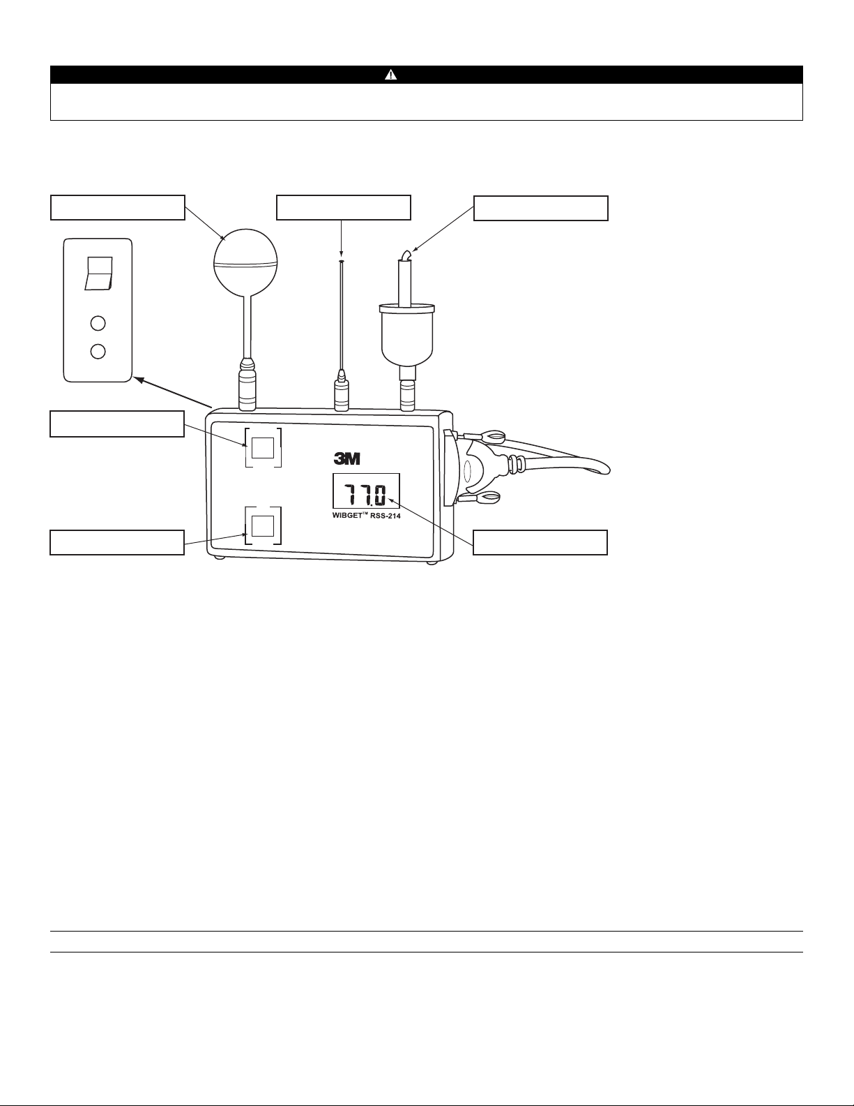
REGISTRO DE DADOS (DATA LOGGING) (Opcional)
FUNCTION
VIEW
OUT WBGT
start
SELECT
MONITOR / log
°C/°F
time base
°F
ON
OFF
Analog
Output
0-1V
Charger
12vdc
Botão FUNCTION (Função)
Sensor de Globo Sensor de Bulbo Seco
Sensor de Bulbo Úmido
Display LCDBotão SELECT (Selecionar)
ADVERTÊNCIA
A porta serial de saída de dados RS 232 do RSS-214DL deve ser utilizada somente em área não classificada. A utilização da porta de saída de dados não é uma
operação intrinsecamente segura. Deixar de seguir esta advertência poderá resultar em enfermidade ou morte.
O acessório de porta serial de saída de dados Data Logger/ RS232C é uma opção que proporciona capacidade de comunicação e de armazenamento de dados digitais não
voláteis (Fig. 3). Até 511 conjuntos de dados (número de registro, hora, data e as cinco funções do monitor) podem ser registrados e descarregados em um computador.
Os dados registrados não serão perdidos se a unidade for desligada, se os sensores forem removidos, na ocorrência de uma falha da bateria, ou se a memória ficar cheia.
Fig. 3
Ajustando e Visualizando o Calendário/Relógio
Ao acionar o interruptor na posição ON, mantenha o botão SELECT pressionado até que o auto-diagnóstico esteja completo e o ano seja exibido (2000 é exibido como “00”).
Para ajustar um parâmetro pressione VIEW, para inserir um valor pressione SELECT.
Uma vez um parâmetro tenha sido inserido, o parâmetro seguinte é exibido seqüencialmente, e a seqüência é:
ano, mês, dia, dia da semana (1 = Domingo, 7 = Sábado), hora (relógio de 24 horas), minutos. Os segundos são zerados se o relógio for alterado, mas não se o relógio for apenas
visualizado. O relógio funciona continuamente enquanto a unidade está desligada e tem a mesma segurança e expectativa de vida útil que os dados no dispositivo de registro.
Modo Registro (Data Log)
Para entrar no Modo de Registro de Dados (Data Log Mode) e salvar sessões de registro de dados anteriores já existentes na memória:
1. Depois de ligar o instrumento, pressione
display exibirá “AP.” (APPEND - ADICIONAR).
2. Para adicionar
(append) dados aos que já se encontram na memória, pressione SELECT (SELECIONAR) novamente. O intervalo de tempo desde a última sessão de
VIEW (VISUALIZAR) e mantenha pressionado, depois pressione SELECT (SELECIONAR), e então solte ambos os botões. O
registro de dados será exibido.
3. Se desejado, o intervalo de tempo poderá ser alterado neste momento, pressionando-se
intervalos de tempo disponíveis são 0,5, 1,0, 2,0, 5,0, 6,0, 10,0, 20,0, e 30,0 minutos.
4. Pressione
SELECT (SELECIONAR) novamente para reiniciar o registro de dados sem apagar quaisquer registros anteriores gravados na memória.
VIEW (base de tempo) para selecionar um intervalo de tempo diferente. Os
Para entrar no Modo de Registro (Log Mode) e apagar todas as sessões anteriores de registro de dados existentes na memória:
1. Pressione
- ADICIONAR).
2. Escolha um intervalo de tempo pressionando
intervalos de tempo disponíveis.
3. Pressione
VIEW (VISUALIZAR) e mantenha pressionado, depois pressione SELECT (SELECIONAR), e então solte ambos os botões. O display exibirá “AP.” (APPEND
VIEW (base de tempo) até que o intervalo de tempo desejado seja exibido. Consulte o passo 3 acima para verificar os
SELECT (SELECIONAR) para começar o registro de dados e apagar todas as sessões anteriores de registro de dados da memória.
Nota: O monitor WIBGET retorna automaticamente ao modo monitor quando a memória está cheia.
47
Page 48

Solicitando Registro
Pressionando-se SELECT (SELECIONAR) a qualquer momento durante o registro de dados ocasionará a adição imediata na memória de um conjunto de dados diferente
dos conjuntos de dados registrados no intervalo de tempo pré-selecionado. Este recurso é útil se um evento fora do comum ocorrer em um momento fora dos intervalos
de tempo pré-selecionados. A título de exemplo, se o registro de dados está sendo feito a intervalos de 30 minutos, e um evento foram do comum ocorrer 14 minutos após
o último registro de 30 minutos, pressionando-se
SELECT (SELECIONAR) esse evento será capturado na memória 14 minutos depois de ocorrido o último registro de 30
minutos, sem afetar o intervalo pré-selecionado de 30 minutos.
Para ativar somente o Registro de Dados por Solicitação:
1. Pressione
2. Pressione
3. Pressionando
VIEW (VISUALIZAR) e mantenha pressionado, depois pressione SELECT (SELECIONAR), e então solte ambos os botões. O display exibirá “AP.” (APPEND - ADICIONAR).
VIEW (Visualizar) até que o display exiba “.0”.
SELECT (SELECIONAR) a qualquer momento adicionará imediatamente um conjunto de dados à memória com anotação da hora. Como não foi
selecionado um intervalo de tempo, o registro de dados ocorre somente quando se pressiona SELECT (SELECIONAR).
Visualizando Durante o Registro
Para visualizar a função enquanto se realiza o registro de dados, pressione VIEW (VISUALIZAR) e mantenha-o pressionado para observar uma função (FUNCTION) em
curso (OUT WBGT, WB, DB, etc.). Soltando e pressionando VIEW (VISUALIZAR), cada uma das funções (FUNCTION) pode ser observada.
Saindo do Modo de Registro de Dados (Data Logging)
Simplesmente desligue o WIBGET com o interruptor ON/OFF (LIGA/DESLIGA). Os dados existentes na memória continuarão gravados na memória.
Saindo do Modo de Registro de Dados e Voltando ao Modo Monitor
Pressione VIEW (VISUALIZAR) e mantenha-o pressionado, depois pressione SELECT (SELECIONAR), e então solte ambos os botões. O display agora se encontrará no modo
monitor exibindo OUT WBGT no display. Pressionar e soltar VIEW (VISUALIZAR) alternadamente exibirá cada função (FUNCTION) (OUT WBGT, WB, DB, etc.) por vez.
DESCARREGANDO DADOS (DOWNLOADING)
Requisitos do Sistema
Os seguintes requisitos mínimos de sistema são necessários para instalar, configurar e operar o programa de software do Monitor de Sobrecarga Térmica 3M™ WIBGET™:
PC ou laptop com sistema operacional Windows 98, 2000 ou XP com Porta Com RS-232 disponível. Nota: Um adaptador DB-9 a DB-25 pode ser necessário para
conectar o cabo RS-232 à porta serial do computador.
Instalando o Software do Monitor de Sobrecarga Térmica WIBGET
1. Feche todos os programas em execução no Windows.
2. Insira o CD do
3. No
Microsoft Explorer (ou em Meu Computador), dê um duplo clique em seu drive de CD (geralmente drive D:) e localize o arquivo Setup.exe.
Software do Monitor de Sobrecarga Térmica WIBGET no drive de CD ROM do PC ou do laptop.
4. Dê um duplo clique no arquivo ou no ícone Setup.exe para iniciar a instalação.
5. Siga as instruções nas telas de
menu para inicializar o programa de Software do Monitor de Sobrecarga Térmica WIBGET. É recomendável manter as pastas e os
nomes de arquivo padrão.
Fazendo Download de Dados
Pode-se fazer o download de dados para um computador enquanto o monitor WIBGET está realizando o registro, sem interrupção de qualquer dessas atividades. Um
programa acionado por menu, contido no CD, proporciona a capacidade de manipular e armazenar dados usando um PC. Nota: Os dados de temperatura do WIBGET são
registrados em graus Celsius. Se desejar leituras em Fahrenheit, pressione SELECT (SELECIONAR) imediatamente antes de descarregar os dados para o computador. Para
fazer o download de dados:
1. Ligue o monitor WIBGET.
2. Conecte o monitor WIBGET ao seu computador através do cabo serial de interface fornecido.
3. Abra o programa de
4. Na tela
5. Um
File (Arquivo), selecione Read WIBGET (Ler WIBGET).
menu de download se abrirá. Selecione Download nesse menu.
6. O monitor WIBGET iniciará o envio de dados. Uma vez completado o
Software do Monitor de Sobrecarga Térmica WIBGET.
download, saia do menu de download. Uma tabela de dados será exibida na tela (semelhante à
da Tabela 1 a seguir).
7. Utilize as outras funções do
menu para analisar, salvar e imprimir os dados.
48
Page 49

RSS-214 WIBGET DATA File: :\WBGT\DATA\SAMPLE.WBG
Upload Date: 2006/09/17 Time: 13.46
Record Number Time
(hh:mm)
Test: 2006/09/17
Wet Bulb Dry
Bulb
Globe WBGT
In Out
Location: Floor CLO Value: 1.0 TWM: IN - 1 hour
2 11:12 16.7 21.6 38.0 23.1 21.4 0.0
3 11:17 19.4 27.4 49.8 28.5 26.3 0.0
4 11:22 19.6 27.7 51.9 29.3 26.9 0.0
5 11:27 19.9 27.8 52.3 29.6 27.2 0.0
6 11:32 19.6 27.3 51.4 29.1 26.7 0.0
7 11:37 19.6 27.6 51.4 29.2 26.8 0.0
8 11:42 19.6 27.5 51.3 29.1 26.8 28.5
9 11:47 19.6 27.5 50.8 28.9 26.6 29.0
10 11:52 19.5 27.3 50.9 28.9 26.5 29.0
11 11:57 19.4 27.2 50.6 28.8 26.4 29.0
12 12:02 19.3 27.1
13 12.07
14 12:12
19.5 27.2 51.2 29.0 26.6 28.9
19.5 27.4 51.2 29.0 26.6 28.9
50.5 28.7 26.3 28.9
15 12:17 19.3 27.3 51.2 20.9 26.5 28.8
16 12:22 19.5 27.3 50.8 20.9 26.5 28.9
17 12.27 19.5 27.3 51.0 28.9 26.6 28.9
18 12:32 19.4 27.6 51.2 28:9 26.6 28.9
19 12:37 19.4 27.4 50.7 28.8 26.4 28.9
20 12:42
21 12:47 19.4 97.4
19:6 27.7 51.3 29.1 26.7 28.9
51.1 28.9 26.5 28.9
22 12:52 19.5 27.4 51.2 29.0 26.6 29.0
23 12:57 19.5 27.5 50.9 29.9 26.5 29.0
24 13:02 19.6 27.6 51.2 29.0 26.7 29.0
25 13:07
26 13:12
27 13:17
28 13:22
19.6 27.8 51.5 29.2 26.8 29.0
19.6 28.0 51.3 29.1 26.8 0.0
19.5 27.8 51.5 29.1 26.7 0.0
10.7 27.9 51.7 29.3 26.9 0.0
29 13:27 19.4 27.3 51.4 29.0 26.6
30 13:32 19.3 27.3 51.2 28.9 26.5
31 13:37 19.4 27.5 51.4 29.0 26.6
Tabela 1 (Saída Típica de Impressora/Tela)
Desc: Sample
Metabolic - TWM
TWM RATE
0.0
0.0
0.0
49
Page 50

MANUTENÇÃO
ADVERTÊNCIA
Nunca altere ou modifique este instrumento. A substituição de componentes poderá prejudicar a segurança intrínseca. Esta ação poderá afetar adversamente o
desempenho do produto e resultar em enfermidade ou morte.
Faça reparos ou substitua peças exclusivamente com os componentes 3M aprovados para esta unidade.
Deixar de seguir esta advertência poderá afetar
adversamente o desempenho do produto e resultar em enfermidade ou morte.
Bulbo Úmido
A operação do Bulbo Úmido com um pavio danificado (por exemplo, descolorido, enrijecido ou que não se possa umedecer) pode resultar em leituras incorretas (altas).
Substituição do Pavio
Para substituir um pavio danificado, puxe-o juntamente com sua esponja diretamente para cima por sobre o sensor. Deslize um novo pavio 3M sobre o sensor de forma
que fique justo na ponta e que alcance o fundo do reservatório. Para evitar derramamento de água, uma esponja 3M bem ajustada deve ser colocada sobre o sensor do
pavio e posicionada na boca do reservatório. Umedecer a esponja e o pavio facilita a retirada e a substituição.
Tratamento da Água
Para máxima exatidão e vida útil mais longa do pavio, deve-se usar água destilada (disponível na maioria das farmácias). Alternativamente, pode-se utilizar água da
torneira desmineralizada. Assegure-se de seguir cuidadosamente as instruções fornecidas com o desmineralizador.
Limpeza
CUIDADO
Evite o uso de materiais de limpeza agressivos, abrasivos e outros solventes orgânicos. Esses materiais podem riscar permanentemente as superfícies e danificar o visor
do display, as etiquetas ou a caixa do instrumento.
Para limpar superfícies externas, utilize um tecido/pano macio umedecido com detergente neutro dissolvido em água morna.
Armazenamento
Retire cada um dos sensores puxando diretamente para cima (NÃO GIRE) pelo colarinho de seu conector. Esvazie o reservatório do Bulbo Úmido e retire o excesso de água
de sua esponja. Coloque todos os componentes de volta em seu devido lugar na maleta de transporte.
BATERIA
ADVERTÊNCIA
A substituição da bateria deve ser feita somente em área não classificada. A substituição da bateria não é uma operação intrinsecamente segura. Utilize somente
baterias aprovadas. Deixar de seguir esta advertência poderá resultar em enfermidade ou morte.
Somente carregue o instrumento em áreas não classificadas usando um carregador de bateria 3M (adaptador AC). A carga e a operação da bateria com um adaptador
AC não são operações intrinsecamente seguras. Não tente carregar as baterias alcalinas. Deixar de seguir esta advertência poderá afetar adversamente o
desempenho do produto e resultar em enfermidade ou morte.
CUIDADO
Observe a polaridade correta ao inserir a bateria. A polaridade está indicada na parte interna do compartimento da bateria.
Este instrumento pode conter uma bateria de hidreto de níquel metálico (NiMH). Descarte a bateria de acordo com as regulamentações locais pertinentes.
O monitor WIBGET é acionado por uma bateria recarregável Ni-MH de 9 V (8.4 V) e é fornecido com um carregador externo. Adicionalmente, o monitor WIBGET pode ser
operado com uma bateria alcalina de 9 V não recarregável ou pelo carregador (adaptador AC).
Carregando
Quando a bateria está perto de perder totalmente a carga, a mensagem “LOBAT” é exibida no canto superior direito do display. Para operação continuada/contínua, ou
simplesmente para recarregar a bateria, conecte o carregador através de seu receptáculo (12 V dc) localizado no lado esquerdo inferior do monitor. A recarga exige um
mínimo de 12 horas. Embora as baterias Ni-MH possam ser recarregadas muitas vezes, eventualmente se degradam, exigindo substituição.
Substituição
Com a alimentação de energia desligada (‘OFF’ ), retire os quatro parafusos da parte traseira da caixa e abra o instrumento. Observando a posição da bateria, substitua-a.
Reinstale a parte posterior da caixa usando o processo inverso.
CALIBRAÇÃO
A unidade base do monitor WIBGET e todos os seus três sensores podem ser enviados de volta à 3M para calibração de acordo com os padrões NIST/INMETRO. Somente
será emitido um CERTIFICADO DE CALIBRAÇÃO DO INSTRUMENTO se a unidade base WIBGET juntamente com todos os seus três sensores tiverem passado pela
calibração. Certificação rastreável e dados de antes/depois também podem ser fornecidos mediante um custo adicional. Recomenda-se que o monitor WIBGET seja
calibrado anualmente.
50
Page 51

SOLUÇÃO DE PROBLEMAS
Use a tabela a seguir para ajudar a identificar possíveis causas e ações corretivas para problemas que eventualmente ocorram. Se precisar de assistência adicional, entre em
contato com seu Centro de Serviços 3M ou ligue para o Serviço Técnico 3M nos EUA, 1-800-243-4630. No Canadá, ligue para o Serviço Técnico em 1-800-267-4414. No
Brasil, entre em contato com a 3M através do Disque-Segurança pelo 0800-0550705.
Problema Possível Causa Possível Solução
A unidade não responde quando é ligada Falha da bateria/carregador. Substitua a bateria
A bateria não dura o tempo adequado Falha da bateria/carregador. Substitua a bateria
Leitura(s) muito alta(s) Conector úmido. Enxágüe o conector com álcool isopropílico e seque-o.
O monitor WIBGET envia dados, mas o PC não os
recebe.
O computador produz dados sem sentido. Configuração incorreta do comutador interno #1
O computador trava Configuração incorreta do comutador interno #3
Configuração incorreta do comutador interno #4
do RSS-214.
do RSS-214.
Re-configure o comutador #4 e reinicie o PC para atualizar
a porta COM.
Ajuste para uma posição alternativa (as taxas de
transferência de dados são 300 ou 1200).
Ajuste para uma posição alternativa.
do RSS-214.
Se aparecer um código ‘E’ no display (mesmo que seja momentaneamente) durante POWER ON/SELF DIAGNOSTICS (LIGA/AUTO-DIAGNÓSTICO), consulte o seguinte:
Código Exibido Possível Causa Possível Solução
E1, E2, E3
E4, E5
E6GT, E6WB, E6DB
Falha de componente Devolver para reparo
Saída analógica fora de calibração Ajuste Trim R para 250 mv a 25,0 °C.
Mau funcionamento de um sensor específico Conecte, limpe ou substitua o(s) sensor(es) afetado(s)
E7, E8 Falha de memória ou bateria fraca Devolva para reparo, ou recarregue/substitua a bateria
PRODUTOS, ACESSÓRIOS E PEÇAS
ADVERTÊNCIA
Nunca altere ou modifique este instrumento. A substituição de componentes poderá prejudicar a segurança intrínseca. Deixar de seguir esta advertência poderá afetar
adversamente o desempenho do produto e resultar em enfermidade ou morte.
Faça reparos ou substitua peças exclusivamente com os componentes 3M aprovados para esta unidade.
Deixar de seguir esta advertência poderá afetar
adversamente o desempenho do produto e resultar em enfermidade ou morte.
Monitores de Sobrecarga Térmica WIBGET
Peça no. Descrição
RSS-214 Monitor de Sobrecarga Térmica 3M™ WIBGET
™
RSS-214DL Monitor de Sobrecarga Térmica 3M™ WIBGET™ com Registro de Dados (Data Logging)
Peças de Reposição e Acessórios
Peça no. Descrição
323-1402 Sensor de Bulbo Seco 3M
323-1203 Sensor de Bulbo Úmido 3M
™
™
323-5020 Kit de Bulbo Úmido 3M™ (contém desmineralizador, 6 pavios e 2 esponjas)
323-1003 Sensor de Globo 3M
323-5025 Bateria NiMH de 9 V e Carregador 3M
227-0500 Bateria NiMH de 9 V 3M
229-0102 Garrafa de água 3M
™
™
™
™
323-2220 Conjunto Pessoal de Sensores 3M™ (com clipe para capacete)
323-2200 Cabo de 3 metros (10 pés) para Montagem de Sensores 3M
323-2201 Cabo de 6 metros (20 pés) para Montagem de Sensores 3M
323-2202 Cabo de 15 metros (50 pés) para Montagem de Sensores 3M
323-2203 Cabo de 30 metros (100 pés) para Montagem de Sensores Remotos 3M
323-2202wp Cabo de 15 metros (50 pés) à prova de intempéries para Montagem de Sensores Remotos 3M
323-2203wp Cabo de 30 metros (100 pés) à prova de intempéries para Montagem de Sensores Remotos 3M
™
™
™
™
™
™
51
Page 52

GARANTIA DO MONITOR DE SOBRECARGA TÉRMICA 3M
™
GARANTIA
A 3M garante que seus Monitores de Sobrecarga Térmica RSS-214 e RSS-214DL estão livres de defeitos de material e mão de obra para o uso em aplicações normais e
sob condições normais, conforme descrito no manual dos produtos, por 1 ano a partir da data de fabricação.
Esta garantia ficará sem efeito se o Monitor de Sobrecarga Térmica da 3M tiver sido danificado por acidente, mau uso, negligência, manutenção inadequada, ou outras
causas não decorrentes de defeitos de material ou mão de obra. Esta garantia não inclui itens substituíveis, tais como pavios, esponjas, desmineralizador e baterias, que
são considerados como sendo parte de um programa regular de manutenção, conforme definido no manual do produto. Quaisquer garantias implícitas oriundas da venda
dos Monitores de Sobrecarga Térmica da 3M, incluindo porém não limitadas às garantias implícitas de comerciabilidade e adequação a uma finalidade específica, estão
limitadas em duração ao prazo estabelecido acima. A 3M não será responsável pela perda do uso de quaisquer de seus produtos ou por custos ou despesas incidentais ou
conseqüentes, ou por danos sofridos pelo comprador ou por qualquer outro usuário.
RECURSO: Se o Monitor de Sobrecarga Térmica da 3M apresentar defeitos no uso normal sob condições normais durante o período de garantia, sem que tal problema
resulte de falha do comprador ou de qualquer outro usuário, o monitor deverá ser devolvido a um centro de serviços de garantia e assistência técnica autorizado da 3M para
análise prévia. Para informações sobre a localização dos centros de serviços de garantia e assistência técnica autorizados da 3M nos EUA, ligue para 1-800-243-4630.
No Canadá, ligue para o Serviço Técnico em 1-800-267-4414. No Brasil, entre em contato com a 3M através do Disque-Segurança pelo 0800-0550705. Os reparos
ou a substituição serão realizados sem custo durante o prazo da garantia ora estabelecido. Cada unidade reparada estará garantida por sessenta (60) dias ou pelo prazo
remanescente da garantia original do equipamento, o que for maior.
EXCLUSÕES DA GARANTIA: A GARANTIA ACIMA É EXCLUSIVA E SUBSTITUI TODAS AS DEMAIS GARANTIAS, EXPRESSAS, IMPLÍCITAS, OU ESTATUTÁRIAS, INCLUINDO A
GARANTIA DE COMERCIABILIDADE, ADEQUAÇÃO PARA UM FIM ESPECÍFICO OU OUTRAS GARANTIAS DE QUALIDADE.
LIMITAÇÃO DE RESPONSABILIDADE: O RECURSO ACIMA CONSTITUI O ÚNICO E EXCLUSIVO RECURSO E SUBSTITUI QUALQUER E TODOS OS DEMAIS RECURSOS
EVENTUALMENTE DISPONÍVEIS. Esta garantia perderá o valor imediatamente caso quaisquer reparos ou alterações no equipamento garantido sejam efetuados sem a
autorização da 3M.
PARA MAIS INFORMAÇÕES
No Brasil, entre em contato:
Disque Segurança: 0800-0550705
Home Page: www.3m.com/br/seguranca
e-mail: faleconosco@3m.com.br
Para outros produtos 3M:
Nos Estados Unidos, entre em contato com:
Internet: www.3M.com/OccSafety
Assistência Técnica: 1-800-243-4630
Para outros produtos 3M:
1-800-3M-HELPS ou 1-651-737-6501
Linha Aberta: 0800-0132333
52
Page 53

535455
Page 54

Page 55

Page 56

3
Occupational Health and Environmental
Safety Division
3M Center, Building 0235-02-W-70
St. Paul, MN 55144-1000
Occupational Health
and Environmental Safety Division
3M Canada Company
P.O. Box 5757 London, Ontario N6A 4T1
Division des produits d’hygiène
industrielle et de sécurité
environnementale de 3M
Compagnie 3M Canada
C.P. 5757
London (Ontario) N6A 4T1
3M México S.A. de C.V.
Av. Santa Fe No. 190
Col. Santa Fe, Del. Álvaro Obregón
México D.F. 01210
3M do Brasil Ltda.
Via Anhangüera, km 110 - Sumaré - SP
CNPJ 45.985.371/0001-08
©3M 2007
34-8700-2541-7
 Loading...