

Page 1
ANSI Z359.4 - 2013
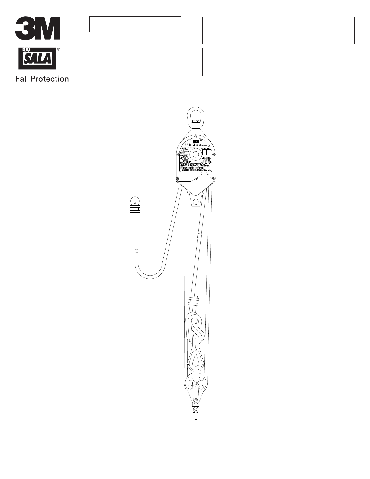
ROLLGLISSTM
Rescue-Positioning Device
USER INSTRUCTIONS
5902114 REv. F
© 3M 2021
Page 2
2
A
B
C
D
E
F
G
H
H
K
M
3 4
A B C
J
A. B. C. D.
E. F. G.
2
Page 3
5 6
FC
1
W
B
A
7 8
2
C
A
A
B
B
3
Page 4
9 10
11 12
A
4
Page 5
13 14
A
B
15
5
Page 6

SAFETY INFORMATION
EN
Please read, understand, and follow all safety information contained in these instructions, prior to the use of this product. FAILURE TO DO SO
COULD RESULT IN SERIOUS INJURY OR DEATH.
These instructions must be provided to the user of the equipment. Retain these instructions for future reference.
Intended Use:
This product is used as part of a complete Fall Protection system.
Use in any other application including, but not limited to, material handling, recreational or sports-related activities, or other activities not described in these
instructions, is not approved by 3M and could result in serious injury or death.
This product is only to be used by trained users in workplace applications.
! WARNING
This product is used as part of a complete Fall Protection system. All users must be fully trained in the safe installation and operation of their complete Fall
Protection system. Misuse of this product could result in serious injury or death. For proper selection, operation, installation, maintenance, and service,
refer to all instruction manuals and manufacturer recommendations. For more information, see your supervisor or contact 3M Technical Services.
• To reduce the risks associated with working with a Rescue Device which, if not avoided, could result in serious injury or death:
- Inspect the product before each use and after any fall event, in accordance with the procedures dened in these instructions.
- If inspection reveals an unsafe or defective condition, remove the product from service immediately and clearly tag it “DO NOT USE”. Destroy or
repair the product as required by these instructions.
- Any product that has been subject to fall arrest or impact force must be immediately removed from service. Destroy or repair the product as
required by these instructions.
- Ensure that Fall Protection systems assembled from components made by different manufacturers are compatible and meet the requirements of
applicable Fall Protection regulations, standards, or requirements. Always consult a Competent or Qualied Person before using these systems.
- Always maintain 100% tie-off.
- Ensure the lifeline is kept free from all hazards, including, but not limited to: entanglement with users, other workers, moving machinery, other
surrounding objects, or impact from overhead objects that could fall onto the lifeline or users.
- Use appropriate edge protection when the lifeline may contact sharp edges or abrasive surfaces.
- Do not twist, tie, knot, or allow slack in the lifeline.
- Do not touch parts of the system exposed to friction during or after a descent; these parts become hot and may cause burns.
- Follow all manufacturer recommendations when connecting a lifeline.
- Always follow your workplace rescue plan when performing rescue operations.
- Do not use this product unless you have received technical rescue training.
- Use caution when installing, using, or moving the product as moving parts may create pinch points.
- Always record descents as specied by these instructions and remove product from service as necessary in accordance with listed usage limits.
- The operator must always maintain control of the hand wheel while the system is under load.
- Always maintain control of the connecting device and descend at a controlled rate.
• To reduce the risks associated with working at height which, if not avoided, could result in serious injury or death:
- Your health and physical condition must allow you to safely work at height and to withstand all forces associated with a fall arrest event. Consult
your doctor if you have questions regarding your ability to use this equipment.
- Never exceed allowable capacity of your Fall Protection equipment.
- Never exceed the maximum free fall distance specied for your Fall Protection equipment.
- Do not use any Fall Protection equipment that fails inspection, or if you have concerns about the use or suitability of the equipment. Contact 3M
Technical Services with any questions.
- Some subsystem and component combinations may interfere with the operation of this equipment. Only use compatible connections. Contact 3M
Technical Services before using this equipment in combination with components or subsystems other than those described in these instructions.
- Use extra precautions when working around moving machinery, electrical hazards, extreme temperatures, chemical hazards, explosive or toxic
gases, sharp edges, abrasive surfaces, or below overhead materials that could fall onto you or your Fall Protection equipment.
- Ensure use of your product is rated for the hazards present in your work environment.
- Ensure there is sufcient fall clearance when working at height.
- Never modify or alter your Fall Protection equipment. Only 3M, or persons authorized in writing by 3M, may make repairs to 3M equipment.
- Before using Fall Protection equipment, ensure a written rescue plan is in place to provide prompt rescue if a fall incident occurs.
- If a fall incident occurs, immediately seek medical attention for the fallen worker.
- Only use a Full Body Harness for Fall Arrest applications. Do not use a body belt.
- Minimize swing falls by working as directly below the anchorage point as possible.
- A secondary Fall Protection system must be used when training with this product. Trainees must not be exposed to an unintended fall hazard.
- Always wear appropriate Personal Protective Equipment when installing, using, or inspecting the product.
- Never work below a suspended load or worker.
FORM NO: 5908259 REV: B
6
Page 7
Prior to installation and use of this equipment, record the product identication information from the ID label in the
;
Inspection and Maintenance Log (Table 2) at the back of this manual.
The user must read and follow the manufacturer’s instructions for each component of the complete system.
;
PRODUCT DESCRIPTION:
Figure 1 illustrates the 3M™ DBI-SALA® Rollgliss™ Rescue-Positioning Device. DBI-SALA rescue and positioning devices are
designed to be components of a rescue-positioning system. This equipment is used for applications where personnel need to be
raised or lowered over a vertical distance.
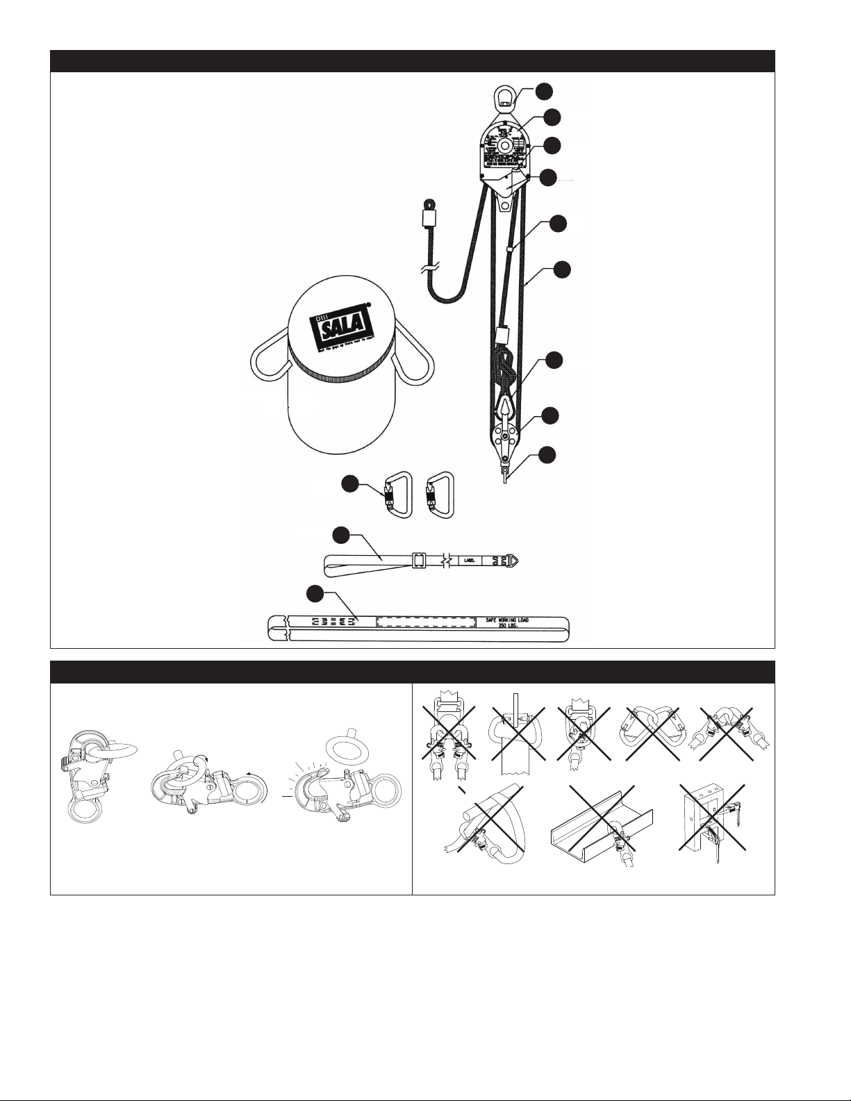
Figure 2 illustrates components of the Device. See Table 1 for Component Specications.
Table 1 – Specications
System Specications:
Capacity:
A maximum of one user can connect to a single Rescue-Positioning Device for rescue or
;
personnel riding applications. In emergency situations, a maximum of two users is allow with a
maximum capacity of 620 lb. (281.2 kg). See below.
Number of
Users
1 310 lb. (140 kg)
2 620 lb. (280 kg)
Lifting Ratio 3:1 - Models 3600000-3601410
4:1 - Models 3602000-3603560
Locking Speed 3 ft./second
Anchorage Strength: Anchorages selected for rescue or personnel riding systems shall have a strength capable of
Service Temperature Do not use where air temperatures exceed 300° F (145°C) or where the rope may come into contact
Anchorage Connector
Breaking Strength:
Standards: The Rescue-Positioning Device has been tested in accordance with the standards identied on the
sustaining static loads applied in the directions permitted by the Rescue Positioning Device of at
least 3,100 lbf (13.8 kN).
When more than one Rescue Positioning Device is attached to an anchorage, the strengths stated
above must be multiplied by the number of devices attached to the anchorage.
with material that is above 250° F (120°C).
5,000 lbf (22.2 kN)
front cover of these instructions.
Total Weight
(including tools, clothing, etc.)
7
Page 8

Component Specications:
Figure 2
Reference
A
B
C
D
E
F
G
H
J
K
L
M
N
P
Component Specications
Swivel Material: Aluminum/Steel
Labels
Indicator Flag
Housing Material: Aluminum
Override Ferrule Material: Stainless steel
Rope
9502091
Teardrop Thimble
Pulley
Carabiner
2000523
Rescue Sling
Connection Sling
3620001
Anchorage Strap
Rope Gripping Handle
9503008 - Optional (Right hand)
9503037 - Optional (Left Hand)
Rescue Cradle
3610000 - Optional
Table 1 – Specications
Material: Plastic
Width: 1/2 in. (1.27 cm)
Material: Kernmantle rope lifeline, braided polyester cover with nylon
lament core
Diameter: 3/8 in. (9.5 mm)
Calculating rope length:
(3:1): Multiply working travel length by 4 and add 10 ft. (3 m) for total.
(4:1): Multiply working travel length by 5 and add 10 ft. (3 m) for total.
Tensile Strength: 5,600 lbf (25 kN)
Material: Plastic
Width: 1/2 in. (1.27 cm)
Material: Zinc plated
Tensile Strength: 5,000 lbf (22 kN)
Material: Wide polyester web construction, drop forged alloy steel
hardware
Width: 1.75 in. (4.4 cm)
Material: Wide latex treated polyester web
Width: 1 in. (2.54 cm)
Length: 3 ft. (0.9 m)
Tensile Strength: 9,800 lbf. (43.6 kN)
Material: Polyester Webbing
Tensile Strength: 9,800 lbf (43.6 kN)
Material: Aluminum body, stainless steel pivots and springs, tempered
steel cam, insulated grip
Weight: 0.43 lb. (0.19 kg)
Material: Treated canvas with polyester web
Capacity: 350 lb. (160 kg)
8
Page 9

1.0 PRODUCT APPLICATION
1.1 PURPOSE: The Rescue-Positioning Device is designed to be a component of a rescue-positioning system. The device is
intended to lower one or two people simultaneously from an elevated height to a lower level in a positioning operation or
rescue situation.
1.2 STANDARDS: Your device conforms to the national or regional standard(s) identied on the front cover of these
instructions. If this product is resold outside the original country of destination, the re-seller must provide these
instructions in the language of the country in which the product will be used.
1.3 SUPERVISION: Use of this equipment must be supervised by a Competent Person¹.
1.4 TRAINING: This equipment must be installed and used by persons trained in its correct application. These instructions are to be used
as part of an employee training program as required by national, regional, or local standards. It is the responsibility of the users and
installers of this equipment to ensure they are familiar with these instructions, trained in the correct care and use of this equipment,
and are aware of the operating characteristics, application limitations, and consequences of improper use of this equipment.
1.5 RESCUE PLAN: When using this equipment and connecting subsystem(s), the employer must have a written rescue plan
and the means to implement and communicate that plan to users², authorized persons³, and rescuers4. A trained, on-site
rescue team is recommended. Team members should be provided with the equipment and techniques necessary to perform a
successful rescue. Training should be provided on a periodic basis to ensure rescuer prociency. Rescuers should be provided
with these instructions.
1.6 AFTER A FALL: If the device is subjected to the forces of arresting a fall, it must be removed from service immediately,
clearly tag it “DO NOT USE”, and then either destroyed or forwarded to 3M for replacement or repair.
2.0 SYSTEM REQUIREMENTS
2.1 CAPACITY: The user capacity of a complete Fall Protection system is limited by its lowest rated maximum capacity component.
For example, if your connecting subsystem has a capacity that is less than your harness, you must comply with the capacity
requirements of your connecting subsystem. See the manufacturer instructions for each component of your system for capacity
requirements.
2.2 DESCENT PATH AND LANDING AREA CLEARANCE: The planned descent path must be unobstructed. The landing
area must be clear of obstructions to permit safe landing of the user. Failure to provide an unobstructed descent path and
landing area may result in serious injury. Maintain a minimum distance of 1 ft. (31 cm) away from any vertical surface to
ensure safe descent.
2.3 ENVIRONMENTAL HAZARDS: Use of this equipment in areas with environmental hazards may require additional
precautions to prevent injury to the user or damage to the equipment. Hazards may include, but are not limited to: heat,
chemicals, corrosive environments, high voltage power lines, explosive or toxic gases, moving machinery, sharp edges, or
overhead materials that may fall and contact the user or device. Contact 3M Technical Services for further clarication.
2.4 SHARP EDGES: Avoid using this equipment where system components will be in contact with, or scrape against, sharp
edges and abrasive surfaces. All sharp edges and abrasive surfaces must be covered with protective material when
contact is unavoidable.
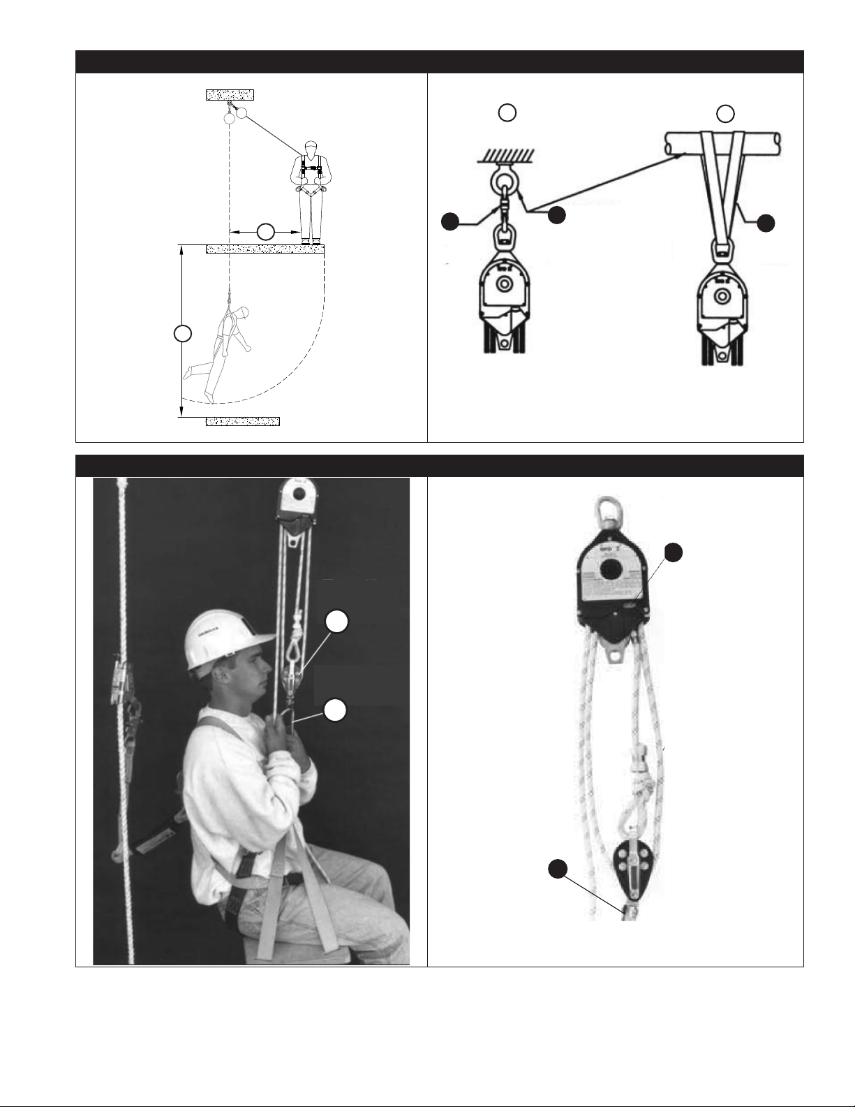
2.5 SWING FALLS: Swing Falls occur when the anchorage point is not directly above the point where a fall occurs (see Figure
5). The force of striking an object in a swing fall may cause serious injury or death. Do not permit a swing fall if injury
could occur. Minimize swing falls by working as directly below the anchorage point as possible. The required Fall Clearance
(FC) of the user increases as User Work Radius (W) increases, since the total fall distance will be greater than if the user
had fallen directly below the anchorage point.
2.6 COMPONENT COMPATIBILITY: 3M equipment is designed for use with 3M approved components and subsystems
only. Substitutions or replacements made with non-approved components or subsystems may jeopardize compatibility of
equipment and may affect the safety and reliability of the complete system.
2.7 CONNECTOR COMPATIBILITY: Connectors are compatible with connecting elements when the size and shape of either
component does not cause the connector to inadvertently open, regardless of orientation. Connectors must comply with
applicable standards. Connectors must be fully closed and locked during use. 3M Connectors (snap hooks and carabiners)
are designed to be used only as specied in each instruction manual. Ensure connectors are compatible with the
system components to which they are connected. Do not use equipment that is non-compatible. Use of non-compatible
components may cause the connector to unintentionally disengage (see Figure 3). If the connecting element to which a
connector attaches is undersized or irregular in shape, a situation could occur where the connecting element applies a
force to the gate of the connector (A). This force could then cause the gate to open (B), disengaging the connector from
the connecting element (C).
1 Competent Person: One who is capable of identifying existing and predictable hazards in the surroundings or working conditions which are
unsanitary, hazardous, or dangerous to employees, and who has authorization to take prompt corrective measures to eliminate them.
2 User: A person who performs activities while protected by a Fall Protection system.
3 Authorized Person: A person assigned by the employer to perform duties at a location where the person will be exposed to a fall hazard
4 Rescuer: A person using the Rescue system to perform an assisted rescue.
9
Page 10

2.8 MAKING CONNECTIONS: All connections must be compatible in size, shape, and strength. See Figure 4 for examples of
inappropriate connections. Do not attach snap hooks and carabiners:
A. To a D-ring to which another connector is attached.
B. In a manner that would result in a load on the gate. Large-throat snap hooks should not be connected to standard-
size D-Rings or other connecting elements, unless the snap hook has a gate strength of 3,600 lbf (16 kN) or greater.
C. In a false engagement, where size or shape of the connector or connecting element is not compatible and, without
visual conrmation, would seem to be fully engaged.
D. To each other.
E. Directly to webbing or rope lanyard or tie-back material, unless the instruction manuals for both the lanyard and
connector specically allow such a connection.
F. To any object whose size or shape does not allow the connector to fully close and lock, or that could cause connector
roll-out.
G. In a manner that does not allow the connector to align properly while under load.
10
Page 11

3.0 INSTALLATION
Installation of the Device must be supervised by a Qualied Person1. The installation must be certied by a
;
Competent Person as meeting the criteria for a Certied Anchorage, or that it is capable of supporting the potential
forces that could be encountered during a fall.
3.1 PLANNING: Plan your Device and how it will be used before starting your work. Account for all factors that may affect
your safety before, during, and after a fall. Consider all requirements, limitations, and specications dened in Section 2
and Table 1.
3.2 INSTALLING THE RESCUE-POSITIONING DEVICE: The anchorage point for the Rescue-Positioning Device must be
capable of supporting a 2,500 lb. minimum static load in the direction of operational pull. The anchor may be a tripod,
building structure, or other suitable anchoring point. The unit may be attached in the following manner:
• Through the top loop in the Rescue-Positioning Device housing using the connection hook. The hook
(A) can be connected directly to the anchor point (B) or to the connection sling which has been attached to the
anchorage via a straight loop, choker, or basket loop. See Figure 6.1.
• Through the top loop in the Rescue-Positioning Device housing using the connection sling. Use a choker or
basket loop to connect the sling to the Rescue-Positioning Device. Attachment can be made directly through the top
loop in the Rescue-Positioning Device housing using the connection sling provided. Use a choker or basket loop to
connect the sling to the Rescue-Positioning Device. See Figure 6.2.
• Rig the Rescue-Positioning Device system directly above the intended working area. If the Rescue-
Positioning Device is not rigged directly overhead, a swing fall situation could occur. Swing falls occur when a worker
swings and strikes an immovable object. See Figure 5.
• After attaching the Rescue-Positioning Device onto the proper anchorage over the working area, attach the travelling
pulley (A) to the personnel support device using a self-locking carabiner (B). See Figure 7.
An independent fall protection system is required by law (OSHA) when using this system during normal work
;
positioning operations. Do not connect fall protection equipment directly to the Rescue-Positioning Device system.
Fall protection systems must be connected to an independent anchor with a minimum tensile strength of 5,000 lbf
(22 kN), measured in direction of possible fall.
4.0 USE
4.1 BEFORE EACH USE: Verify that your work area and Fall Arrest System meet all criteria dened in Section 2 and that
a formal Rescue Plan is in place. Inspect the Rescue-Positioning Device per the ‘User’ inspection points dened on the
“Inspection and Maintenance Log” (Table 2). If inspection reveals an unsafe or defective condition, do not use the device.
Remove the device from service and destroy, or contact 3M regarding replacement or repair.
4.2 BODY SUPPORT: When using the Rescue-Positioning Device, it is recommended that a work-seat or boatswain’s chair be
used. A full body harness should also be worn for connection to the independent Fall Protection system. The D-ring on the
back between the shoulders (dorsal D-ring) should be used to connect the personal fall protection system.
Do not use a body belt with this equipment. Body belts do not support your entire body, which may result in
;
serious injury.
4.3 ANCHORAGE: Anchorage connections shall be stabilized to prevent unwanted movement or disengagement of the Rescue
System from the anchorage. Verify the system connection by pretensioning the system before applying the intended load.
Anchorage connectors must not be attached to anchorages where such attachment would reduce the anchorage system
strength below the anchorage specifcations in Table 1.
Anchorage requirements vary with the fall protection application. The mounting structure on which the equipment is placed
must meet the Anchorage specications dened in Table 1. A suitable anchorage connector shall be used for rigging the
connection of lanyards and lifelines to structural members. A lanyard shall not be connected back onto itself for use as an
anchorage connector unless designed for this purpose.
Anchorages used in fall arrest applications must conform to ANSI Z359.2. When an anchorage is used for both fall
;
arrest and rescue applications, the greater load requirements shall apply.
4.4 FALL CLEARANCE: Should the operator release the line while in the free mode, there must be sufcient clearance in the area
below to avoid hitting an obstruction or a lower level. Fall clearance is the measure of distance between a user and the next
obstruction below them. Before use of this product, the user should determine how much Fall Clearance is necessary to prevent
them from striking an obstruction should they fall. With the anchorage located directly overhead, it is recommended that a
minimum of 2 ft. (0.6 m) of clearance be maintained between the work level and the nearest obstruction in the fall path.
4.4 APPLICATIONS: The Device may be used in the following methods:
A. Positioning: In this application, the Rescue-Positioning Device is used as part of a complete positioning and personnel
riding system. Such systems typically include a full body harness, boatswain’s chair or work-seat, independent personal
fall protection system, and the Rescue-Positioning Device.
B. Rescue: In this application, the Rescue-Positioning Device is used as part of a complete rescue system. Such systems
typically include a full body harness or rescue sling, anchorage connector (i.e. carabiner, etc.) and the Rescue-Positioning
Device.
11
Page 12

When using this equipment for personnel, federal law (OSHA) requires a secondary or back-up Fall Protection
;
system be used. The back-up or secondary fall protection system is not required in applications where the RescuePositioning Device is only used to retrieve personnel (i.e. emergency rescue operations).
4.5 OPERATION OF THE RESCUE-POSITIONING DEVICE:
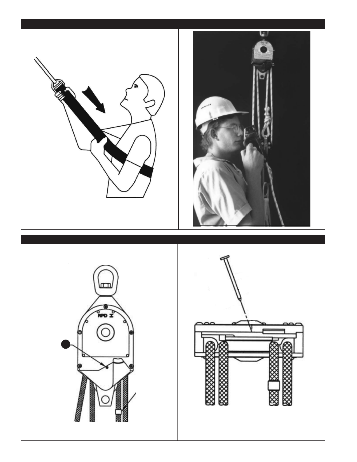
A. Before securing the Rescue-Positioning Device system, operate the unit so the silver indicator ag (A) is showing and
the unit is in a locked position. Pull down the connector (B) to ensure the device is locked. See Figure 8.
B. Connect yourself or other worker to the personnel support device. If the rescue sling is used, slip it over the shoulders.
Position the rescue sling below the arms and move the adjuster buckle to tighten. See Figure 9. If a work-seat, accident
cradle (3610000), or other support device is used, follow the instructions for that equipment.
C. To raise, pull on the free end of the rope with a smooth hand-over-hand action or use the optional rope gripping
handle. To lock it in position, raise until the silver indicator ag is showing. Gradually release the rope. See Figure 10.
D. To lower, grasp the free rope and raise it slightly until the orange indicator ag appears. This will occur approximately
every two inches (5 cm) of personnel travel. When the orange indicator appears, lowering may begin. Lower by using a
hand-over-hand action or the optional gripping handle. To position, raise slightly until the indicator ag is showing silver.
The unit will now be locked in position. Always maintain safe speeds when raising or lowering. See Figure 10.
An optional rope gripping handle (9503008 right hand, 9503037 left hand) may be used to aid in raising or lowering
operations. To operate, pull back on the spring loaded jaw and insert the rope. Raise or lower as required. To reposition,
release the jaw and move it to the desired location. Release the jaw to lock it in place. See Figure 10. An optional method
to aid in lowering yourself can be used; the free rope end can be passed through a D-ring and/or connecting hook and
then controlled easily by hand. Raising or lowering may be done by the user or an assistant.
If rope tension eases during lowering, the person being lowered may have reached a work level or obstruction.
;
Do not continue operation without communicating with the person being lowered. Always maintain tension on the
personnel line. Slack line could cause a free fall situation.
Do not use the Rescue-Positioning Device for lifting or lowering more than one person per trip.
;
Operate the device by manual power only. Do not use power winches or other similar devices to operate this
;
system.
4.6 AFTER A RESCUE: The Rescue-Positioning Device must be removed from service following use in a rescue event. The
Rescue-Positioning Device should then be destroyed or sent to an authorized service center for inspection and repair.
4.7 USE WITH A HORIZONTAL SYSTEM: In applications where the Rescue-Positioning Device is used in conjunction with
a horizontal system, compatibility between the Rescue-Positioning Device and horizontal system components must be
achieved. Horizontal systems must be designed and installed under the supervision of a qualied person.
5.0 INSPECTION
Inspection criteria must be set by the user or manufacturer and cannot be less than what is specied in these
;
intstructions.
5.1 INSPECTION FREQUENCY:
additionally, by a Competent Person other than the user monthly and annually. Extreme working conditions (harsh
environment, prolonged use, etc.) may require increasing the frequency of inspections. Annual servicing shall include, but
not be limited to, an intensive inspection and cleaning of all internal and external components. Failure to provide proper
service may considerably shorten product life and could endanger performance. A record of annual service dates can
be found on the face label of the Rescue-Positioning Device. Inspection procedures are described in the “Inspection and
Maintenance Log” (Table 2). Results of each User and Competent Person inspection should be recorded on copies of the
“Inspection and Maintenance Log”.
5.2 DEFECTS: If inspection reveals an unsafe or defective condition, remove the Rescue-Positioning Device from service
immediately and tag it “DO NOT USE”. Do not attempt to repair the device. Only 3M or parties authorized in writing by 3M
may make repairs to this equipment.
5.3 PRODUCT LIFE: The functional life of the Rescue-Positioning Device is determined by work conditions and maintenance.
As long as the product passes inspection criteria, it may remain in service.
The Rescue-Positioning Device shall be inspected by the user before each use and,
6.0 MAINTENANCE, SERVICING, STORAGE
6.1 CLEANING: Periodically clean the exterior of the device with water and mild detergent. Position the device so excess
water will drain out. Clean labels as required.
• Rope: Clean rope with water and mild detergent. Rinse and thoroughly air dry. Do not force dry with heat.
Immediately wash the entire rope assembly if it has been exposed to acidic vapors.
If the rope comes in contact with liquid or solid acids, remove it from service and wash it with a water and mild
;
detergent solution. Do not return the system to service without it rst being inspected by a qualied inspector.
Acids in contact with rope for extended periods of time can weaken the rope without visible evidence of damage.
Only a qualied inspector can determine rope status.
12
Page 13

6.2 SERVICE: Only 3M or parties authorized in writing by 3M may make repairs to this equipment. If the Rescue-Positioning
Device has been subject to fall force or inspection reveals an unsafe or defective conditions, remove the system from
service and destroy. Rope replacement, as well as additional maintenance and servicing procedures, must be completed
by a factory authorized service center.
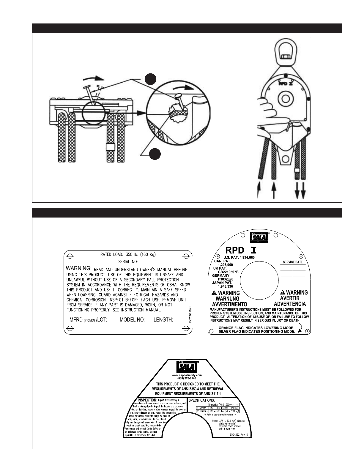
6.4 EMERGENCY RELEASE OF JAMMED ROPE: If the load has been raised very close to the Rescue-Positioning Device unit,
it may not appear possible to reach the lowering mode (orange indicator). However, an override system consisting of an
override ferrule and lever (see steps 1 & 3) is provided to release the brake. To override the brake, continue raising the
load and then lower it. Repeat as required until lowering mode is reached. If this does not work, remove the load and use
the procedure below:
Step 1: Remove the load and the screw or plug (A). See Figure 11.
Step 2: Insert a nail or similar object at an angle into the screw hole. The nail should be 2 in. (2.54 cm) long with 1/8
in. (.32 cm) diameter. See Figure 12.
Step 3: Tip the nail (A) as shown to activate the brake over-ride lever. The brake override lever (B) is located internally
on the side opposite the nail. The override lever may be partially visible through the screw hole. Some force
may be required to move the override lever. See Figure 13.
Step 4: While maintaining pressure on the nail, pull down on the line as shown. Pull out enough line to easily allow the
lowering mode to be reached. Replace the screw or plug. See Figure 14.
6.3 STORAGE AND TRANSPORT: Store and transport the Rescue Positioning Device in a cool, dry, clean environment out of
direct sunlight. Avoid areas where chemical vapors may exist. Thoroughly inspect the device after extended storage.
6.4 CHEMICAL HAZARDS: Solutions containing acids, alkali or other caustic chemicals, particularly at elevated
temperatures, may damage the Rescue-Positioning Device. When working with such chemicals, frequent inspection of
the Rescue-Positioning Device must be completed. Contact 3M if doubt exists concerning use of this equipment around
chemical hazards.
6.5 HEAT: The Rescue-Positioning Device is not intended for use in environments where incendiary sparking could cause an
explosion or re. Use of this equipment is prohibited where there the rope could come in contact with power lines, live
cables, etc. See Table 1 for maximum service temperature.
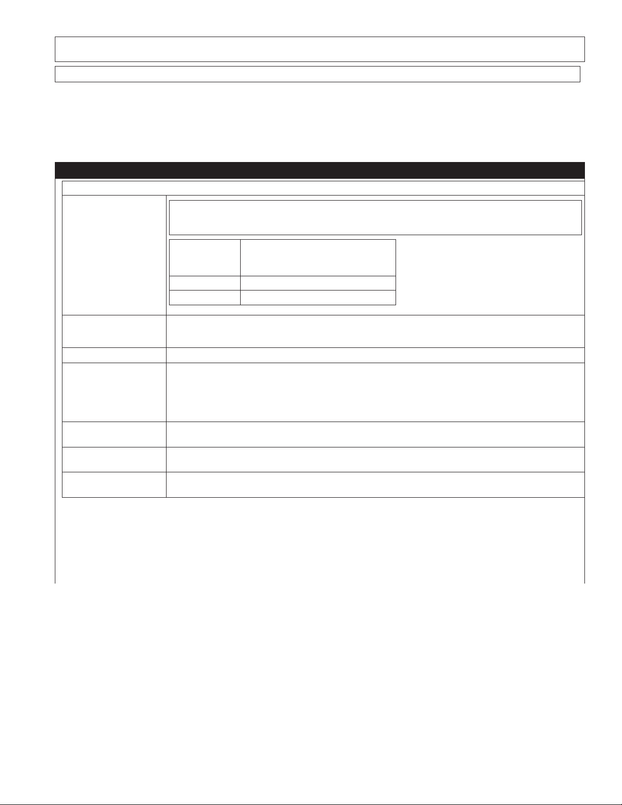
7.0 LABELS
Figure 15 illustrates labels present on the Device. Figure 2 (B) shows where the labels are located. Labels must be replaced if
they are not present and fully legible.
13
Page 14

Table 2 – Inspection and Maintenance Log
Inspection Date: Inspected By:
Component: Inspection: (See Section 5 for Inspection Frequency) User Competent
Person
Rescue-Positioning
Device
(Figure 2)
Labels
(Figure 15)
Fall Arrest System and
Other Equipment
Inspect hardware for cracks, sharp edges, deformation, corrosion,
chemical attack, excessive heating, alternation, or excessive wear. Inspect
loose fasteners and bent or damaged parts.
Inspect the housing for distortion, cracks or other damage. Ensure the
anchorage point is not damaged or distorted in any way (the RPD has a
swiveling anchorage point).
Inspect the rope for fraying, unsplicing, unlaying, kinking, knotting,
roping, broken or pulled stiches, excessive elongation, excessive soiling,
abrasion, alteration, needed or excessive lubrication, excessive aging or
wear. Check for contact with acids or other chemicals.
Inspect the compression sleeves on both ends of the rope. The rope
should fully pass through each sleeve twice. Ensure the compression
sleeve is not cracked.
Check the pulleys for any sign of wear or strain. Check for distortion in the
connecting loops.
Do not disassemble the Rescue-Positioning Device block. It is not user
serviceable. See section 6.
Inspect the entire unit for signs of corrosion.
With the unit properly mounted from a sturdy structure, test the overspeed protection system:
1. Position the travelling pulley approximately 4 ft. (1.2 m) below the
Rescue-Positioning block.
2. Position the system so the orange indicator ag can be seen
and is to the side nearest you.
3. With the right hand, grasp the rope exiting the right side of the RescuePositioning Device. Grip it near the bottom of the housing.
4. With the left hand, lightly restrain the free end of the rope.
5. Pull down sharply with the right hand to engage the over-speed
brake. The unit should lock up. If the brake fails to engage, immediately
remove the unit from service.
Operate the system in both directions. Keep a moderate back pressure on
the rope.
A. The indicator ag should cycle between the locking mode (silver)
and the lowering mode (orange) as the system is being raised.
B. The orange ag should be visible when the system is in lowering mode.
C. The silver ag should be visible when the system is in a locking
(positioning) mode.
Ensure that all labels are present and fully legible.
Additional Fall Arrest System equipment (harness, SRD, etc.) that are used
with the Rescue-Positioning Device should be installed and inspected per
the manufacturer’s instructions.
Serial Number(s): Date Purchased:
Model Number(s): Date of First Use:
Corrective Action/Maintenance: Approved By: Next inspection due:
Date:
Corrective Action/Maintenance: Approved By: Next inspection due:
Date:
Corrective Action/Maintenance: Approved By: Next inspection due:
Date:
Corrective Action/Maintenance: Approved By: Next inspection due:
Date:
Corrective Action/Maintenance: Approved By: Next inspection due:
Date:
14
Page 15
Corrective Action/Maintenance: Approved By: Next inspection due:
Date:
Corrective Action/Maintenance: Approved By: Next inspection due:
Date:
Corrective Action/Maintenance: Approved By: Next inspection due:
Date:
Corrective Action/Maintenance: Approved By: Next inspection due:
Date:
Corrective Action/Maintenance: Approved By: Next inspection due:
Date:
Corrective Action/Maintenance: Approved By: Next inspection due:
Date:
Corrective Action/Maintenance: Approved By: Next inspection due:
Date:
Model numbers:
3:1 4:1
3600000
3600001
3600002
3600008
3600009
3600010
3600012
3600015
3600016
3600018
3600019
3600020
3600022
3600023
3600025
3600026
3600029
3600030
3600032
3600035
3600039
3600040
3600041
3600043
3600045
3600050
3600050F
3600055
3600057
3600060
3600065
3600068
3600070
3600072
3600075
3600080
3600085
3600090
3600094
3600098
3600099
3600100
3600100F
3600110
3600115
3600120
3600120F
3600123
3600125
3600130
3600140
3600140F
3600150
3600160
3600165
3600170
3600170F
3600175
3600180
3600190
3600200
3600210
3600230
3600250
3600264
3600265
3600275
3600280
3600290
3600300
3600312
3600330
3600350
3600400
3600410
3600450
3600500
3600501
3600503
3600504
3600505
3600506
3600507
3600508
3600509
3602000
3602006
3602008
3602010
3602012
3602013
3602014
3602015
3602016
3602017
3602018
3602020
3602021
3602022
3602023
3602024
3602025
3602026
3602027
3602028
3602029
3602030
3602031
3602032
3602033
3602034
3602035
3602037
3602038
3602040
3602042
3602045
3602048
3602049
3602050
3602051
3602052
3602055
3602058
3602060
3602063
3602051
3602052
3602055
3602058
3602060
3602063
3602064
3602065
3602066
3602282
3602300
3602310
3602325
3602340
3602358
3602068
3602070
3602074
3602075
3602078
3602080
3602082
3602085
3602087
3602090
3602093
3602098
3602099
3602100
3602101
3602102
3602108
3602110
3602112
3602118
3602120
3602125
3602128
3602130
3602132
3602135
3602138
3602140
3602150
3602151
3602160
3602165
3602170
3602172
3602175
3602180
3602190
3602200
3602210
3602215
3602228
3602240
3602250
3602260
3602275
3602280
15
Page 16
USA
3833 SALA Way
Red Wing, MN 55066-5005
Toll Free: 800.328.6146
Phone: 651.388.8282
Fax: 651.388.5065
3Mfallprotection@mmm.com
Brazil
Rodovia Anhanguera, km 110
Sumaré
CEP: 13181-900
Brasil
Phone: 0800-013-2333
falecoma3m@mmm.com
Mexico
Av. Santa Fe No. 190
Col. Santa Fe, Ciudad de Mexico
CP 01219, Mexico
Phone: 01 800 120 3636
3msaludocupacional@mmm.com
GLOBAL PRODUCT WARRANTY, LIMITED REMEDY
AND LIMITATION OF LIABILITY
WARRANTY: THE FOLLOWING IS MADE IN LIEU OF ALL WARRANTIES OR CONDITIONS, EXPRESS
OR IMPLIED, INCLUDING THE IMPLIED WARRANTIES OR CONDITIONS OF MERCHANTABILITY OR
FITNESS FOR A PARTICULAR PURPOSE.
Unless otherwise provided by local laws, 3M fall protection products are warranted against factory
defects in workmanship and materials for a period of one year from the date of installation or fi rst use
by the original owner.
LIMITED REMEDY: Upon written notice to 3M, 3M will repair or replace any product determined by
3M to have a factory defect in workmanship or materials. 3M reserves the right to require product be
returned to its facility for evaluation of warranty claims. This warranty does not cover product damage
due to wear, abuse, misuse, damage in transit, failure to maintain the product or other damage beyond
3M’s control. 3M will be the sole judge of product condition and warranty options.
This warranty applies only to the original purchaser and is the only warranty applicable to 3M’s fall
protection products. Please contact 3M’s customer service department in your region for assistance.
LIMITATION OF LIABILITY: TO THE EXTENT PERMITTED BY LOCAL LAWS, 3M IS NOT LIABLE
FOR ANY INDIRECT, INCIDENTAL, SPECIAL OR CONSEQUENTIAL DAMAGES INCLUDING, BUT NOT
LIMITED TO LOSS OF PROFITS, IN ANY WAY RELATED TO THE PRODUCTS REGARDLESS OF THE
LEGAL THEORY ASSERTED.
– SP
WEBSITE:
3M.com/FallProtection
Canada
600 Edwards Blvd, Unit #2
Mississauga, ON L5T 2V7
Phone: 905.795.9333
Toll-Free: 800.387.7484
Fax: 888.387.7484
3Mfallprotection-ca@mmm.com
EME A (Europe, Middle East, Africa)
EMEA Headquarters:
Le Broc Center
Z.I. 1re Avenue - BP15
06511 Carros Le Broc Cedex
France
Phone: + 33 04 97 10 00 10
Fax: + 33 04 93 08 79 70
informationfallprotection@mmm.com
Australia & New Zealand
137 McCredie Road
Guildford
Sydney, NSW, 2161
Australia
Toll-Free : 1800 245 002 (AUS)
Toll-Free : 0800 212 505 (NZ)
3msafetyaucs@mmm.com
ISO
9001
FM534873
Asia
Singapore:
1 Yishun Avenue 7
Singapore 768923
Phone: +65-6450 8888
Fax: +65-6552 2113
TotalFallProtection@mmm.com
China:
38/F, Maxdo Center, 8 Xing Yi Rd
Shanghai 200336, P R China
Phone: +86 21 62753535
Fax: +86 21 52906521
3MFallProtecton-CN@mmm.com
Korea:
3M Koread Ltd
20F, 82, Uisadang-daero,
Yeongdeungpo-gu, Seoul
Phone: +82-80-033-4114
Fax: +82-2-3771-4271
TotalFallProtection@mmm.com
Japan:
3M Japan Ltd
6-7-29, Kitashinagawa, Shinagawa-ku, Tokyo
Phone: +81-570-011-321
Fax: +81-3-6409-5818
psd.jp@mmm.com
EU DECLARATION OF CONFORMITY:
3M.com/FallProtection/DOC
 Loading...