

Page 1
Page 2
JNPS-0813 B
目 次 / CONTENTS
頁 / PAGE
1. 機能 ·················································································································1
FUNCTION············································································································6
2. 適合対象 ········································································································· 1
COMPATIBLE OBJECTS ····················································································· 6
3. 関連仕様図 ·····································································································1
RELATED SPECIFICATION DRAWINGS ························································ 6
4. 関連規格類 ·····································································································1
RELATED TEST STANDARDS ········································································· 6
5. 適用 ·················································································································2
APPLICATION······································································································7
6. 品質特性 ·······································································································3
QUALITY PERFORMANCE·················································································8
7. 製品上めっき仕様識別表示 ··········································································5
PLATING SPEC INDICATION ON CONNECTOR············································10
8. 包装&表示 ·····································································································5
PACKAGE & IDENTIFICATION ······································································· 10
9. 保管 ·················································································································5
STORAGE············································································································10
10. 注意事項 ········································································································· 5
ATTENTIONS ····································································································· 10
i
Page 3
JNPS-0813 B
1. 機能
当該コネクタは、MDR ボードマウントリセプタクル ライトアングルタイプの一つとして、嵌合部は 1.27
mm ピッチ2列の雌コンタクトを持ち、コンタクトテール側は、4列千鳥格子(1.27mm×1.905mm)配列の
端子を有し、コネクタはそれに適するパターンを持つ基板に実装される。
そして、MDR プラグと嵌合することにより、電気信号を授受する機能を発揮する。
2. 適合対象
2-1 適合コネクタ
3M 印 MDR プラグ 101XX-XXXX XX
2-2 適合基板
PCB 推奨ホールパターン図は、関連仕様図類による。
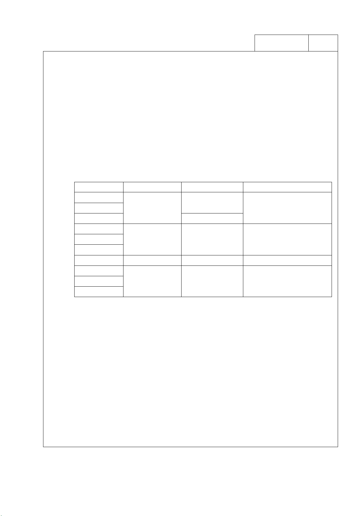
製品番号 基板止め方法 基板止め穴径 適合基板厚
102XX-520X XX
102XX-521X XX
102XX-524X XX
102XX-52AX XX
102XX-52BX XX
102XX-52EX XX
102XX-52DX XX グランドロックタイプ 2 φ2.8mm 1.6 mm または 1.2 mm
102XX-52FX XX
102XX-52GX XX
102XX-52HX XX
ねじ止め
グランドロックタイプ 1 φ2.6mm 1.6mm
グランドロックタイプ 3
2-3 適合パネル
パネル厚: 2.0 mm 以下(ワッシャ等を含む。)
パネルカットアウト図は、関連仕様図類による。
3. 関連仕様図
JNPD-0813 による。
φ2.8 mm
φ3.2 ㎜
φ2.8 mm (推奨)
またはφ2.6 ㎜
テール長 3.9mm 時: 3.0mm 以下
2.8mm時: 1.6mm以下
2.3mm時: 1.2mm以下
0.6 mm 以上 1.6 mm 以下
4. 関連規格類
MIL-STD-202
JEIDA-38-1984
JIS C 0050
JNTM-0039、JNTM-0040
* JNTM: 住友スリーエム(株) 電気・電子製品試験方法規格
1
Page 4
JNPS-0813 B
5. 適用
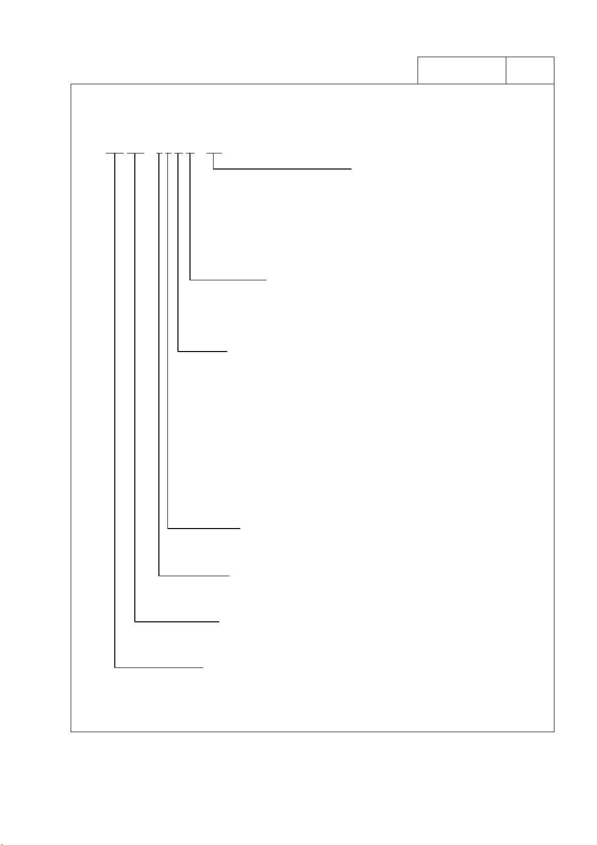
製品番号体系図
102 XX – 5 2 X X PX
テール仕様
2 : 3.9mm
3 : 2.8mm
4 : 2.3mm
固定方法
0 : パネル/ねじ固定(M2.6) 及び 基板/ねじ固定(M2.6)
1 : パネル/ねじ固定(M2.5) 及び 基板/ねじ固定(M2.5)
4 : パネル/ねじ固定(No.4 - 40) 及び 基板/ねじ固定(No.4 - 40)
A : パネル/ねじ固定(M2.6) 及び 基板/グランドロックタイプ 1 仮固定
B : パネル/ねじ固定(M2.5) 及び 基板/グランドロックタイプ 1 仮固定
D : パネル/ねじ固定(M2.6) 及び 基板/グランドロックタイプ 2 仮固定
E : パネル/ねじ固定(No.4 - 40) 及び 基板/グランドロックタイプ 1 仮固定
F : パネル/ねじ固定(M2.6) 及び 基板/グランドロックタイプ 3 仮固定
G : パネル/ねじ固定(M2.5) 及び 基板/グランドロックタイプ 3 仮固定
H : パネル/ねじ固定(No.4 - 40) 及び 基板/グランドロックタイプ 3 仮固定
めっき仕様
PL : ニッケル下地めっき
接点部/金めっき 0.2 µm 以上
テール部/金フラッシュめっき
ルプリカント処理あり
PE : ニッケル下地めっき
コンタクト部/金めっき 0.5 µm 以上
テール部/金フラッシュめっき
PC : ニッケル下地めっき
接点部/金めっき 0.76 µm 以上
テール部/金フラッシュめっき
型式
2 : 標準型
テール形状
5 : ボードマウント ライトアングル型
極数表示
XX : XX 極 (ただし、100 芯は A0 と表示する。)
製品シリーズ名称
102 : MDR リセプタクル
2
Page 5

JNPS-0813 B
6. 品質特性
6-1 定格
項 目 定 格
定格電流
定格電圧
使用温度
AC: 150V Max. / DC: 200V Max.
0.5A Max.
-55℃ ~ 85℃
6-2 物理的特性 *( )内の数値は参考値
項 目 規 格 試 験 条 件 準拠規格
コンタクト保持力
挿抜力
コンタクト
半田付け性
半田耐熱性
7.85N (0.8 kgf) 以上
挿入力 :
1.47N (150 gf) 以下
抜去力 :
0.39N (40 gf) 以上
95%以上のぬれ 又は
ゼロクロスタイム: 3 秒以下
試験後、外観的に著しい変
形のなきこと。
抜去スピード 5 mm/分で測定する。
弊社プラグとの組み合わせによる。
挿抜スピード 5 mm/分で測定する。
規格は、単極当たりの算出値。
Sn-3Ag-0.5Cu はんだ使用
- ぬれ性評価: 245℃、3 秒浸漬
- メニスコグラフ法: 245℃
浸漬半田:
260℃、10 秒、2 回 又は
263℃、5 秒、2 回 まで
*但し、プリヒートは、部品表面温度が
100℃以下、60 秒以内
手半田:
390℃、3 秒、2 回まで
―――
―――
JNTM-0039
JIS C 0050
JNTM-0040
3
Page 6

JNPS-0813 B
6-3 電気的特性
項 目 規 格 試 験 条 件 準拠規格
耐電圧
絶縁抵抗
瞬断
接触抵抗
漏れ電流 1 mA 以内で
絶縁破壊が発生しない
こと。
500 MΩ以上 隣接コンタクト間に DC500V 印加し、1 分後、
試験中に 1μsec 以上の瞬
断が発生しないこと。
初期接触抵抗
各めっき仕様共通
35 mΩ以下
各種環境試験後の
接触抵抗変化
各めっき仕様共通
±25 mΩ以下
隣接コンタクト間に AC500V・RMS を 1 分間印
加。
測定する。
・ 振動試験
3MシーケンスⅡの 1 試験として実施
・ 衝撃試験
抵抗測定電流 1.5 mA、開放電圧 20 mV の
4 端子法にて測定する。
(弊社適合コネクタとの組み合わせ時であり、
バルク抵抗を含む。)
(1) PL めっき
3M シーケンス Ⅰ/
30 回挿抜→耐湿試験→塩水噴霧試験
3M シーケンス Ⅱ/
熱衝撃試験→湿度試験→振動試験
3M シーケンス Ⅲ/
高温寿命試験
H2S ガスシーケンス/
30 回挿抜→H2S ガス試験
耐久挿抜試験/
300 回挿抜
(2) PE めっき及び PC めっき
3M シーケンス Ⅰ/
50 回挿抜→耐湿試験→塩水噴霧試験
3M シーケンス Ⅱ/
熱衝撃試験→湿度試験→振動試験
3M シーケンス Ⅲ/
高温寿命試験
H2S ガスシーケンス/
50 回挿抜→H2S ガス試験
耐久挿抜試験/
500 回挿抜
※各種環境試験条件は表 1 参照。
―――
―――
表1参照
表1参照
4
Page 7

JNPS-0813 B
表 1: 各種環境試験条件
試験項目 試 験 条 件 準拠規格
耐湿試験 -10~65℃、相対湿度 95%/10 サイクル MIL-STD-202F106D
塩水噴霧試験 塩化ナトリウム 5%溶液、35℃/48 時間 MIL-STD-202F101D
熱衝撃試験 -55℃→25℃→85℃→25℃/5 サイクル MIL-STD-202F107G
湿度試験
(定常状態)
高温寿命試験 定常電流:定格電流×110%、85℃/1000 時間 ―――――――
H2S ガス試験 濃度 3±1 ppm、40℃、相対湿度 70~80% 96 時間 JEIDA-38-1984
振動試験
衝撃試験
40℃、相対湿度 95%/96 時間 MIL-STD-202F103B
2
10→55Hz、振幅 1.52mm 又は 98m/s
1 分間掃引/X・Y・Z 方向各 2 時間
2
490m/s
X・Y・Z方向各3回(計9回)
、11m 秒 正弦半波、
、
MIL-STD-202F201A
MIL-STD-202E213B
7. 製品上めっき仕様識別表示
製品上の刻印によるロット番号(アルファベット3文字)表示の一文字目は、下記のめっき仕様を示す。
R
XX : PL めっき
Z
XX : PE めっき
XX : PC めっき
Y
* XX は、アルファベット2文字を示す。
8. 包装&表示
本品は、プラスチックトレイに納め、更にカートンにて梱包された形態で出荷される。
本品のカートンには、次に示す事項が記入されている。
1) 品名 2) 数量 3) 製造者名 4) ロット番号
9. 保管
無負荷、常温(5~35℃)、常湿(40~70%)の室内で、納入時の梱包状態にて保管すること。
10. 注意事項
10-1 コネクタの固定
コネクタは、使用に際し、パネルとのねじ止めを行なうことを推奨いたします。
5
Page 8

JNPS-0813 B
1. FUNCTION
This connector is one of MDR board mount receptacle right angle series. And mating side has 2 rows of
female contacts with the pitch of 1.27mm and contact tails are arranged in 1.27mm×1.905mm staggered
grid. This connector can be mounted on the compatible PC board and mating with MDR plug connector
enable to have the electrical performance.
2. COMPATIBLE OBJECTS
2-1 COMPATIBLE CONNECTORS
3M BRAND MDR PLUG : 101XX-XXXX XX
2-2 COMPAIBLE PC BOARDS
PCB with solder plating hole
See RELATED SPECIFICATION DRAWINGS recommended hole pattern.
PRODUCT No.
PCB RETENSION
METHOD
PCB RETENSION
HOLE DIA.
PCB THICKNESS
102XX-520X XX
102XX-521X XX
102XX-524X XX
102XX-52AX XX
102XX-52BX XX
102XX-52EX XX
102XX-52DX XX
102XX-52FX XX
102XX-52GX XX
102XX-52HX XX
SCREW LOCK
GROUND LOCK TYPE1
GROUND LOCK TYPE2
GROUND LOCK TYPE3
φ 2.8 mm (recommended)
φ 2.8 mm
φ 3.2 mm
φ 2.6 mm
φ 2.8 mm
or φ 2.6 mm
2-3 COMPATIBLE PANELS
Thickness of panels: 2.0 mm Max. (Including with the thickness of washers)
See RELATED SPECIFICATION DRAWINGS for recommended panel cut-out.
3. RELATED SPECIFICATION DRAWINGS
See the drawings described in JNPD-0813.
3.9 mm Tail: 3.0 mm Max.
2.8 mm Tail: 1.6 mm Max.
2.3 mm Tail: 1.2 mm Max.
1.6 mm
0.6 mm or 1.2 mm
0.6 mm Min.
1.6 mm Max.
4. RELATED TEST STANDARDS
MIL-STD-202
JEIDA-38-1984
JIS C 0050
JNTM-0039, JNTM-0040
*JNTM: Test Method Standard of Sumitomo 3M for Electronic and Electrical Component Parts.
6
Page 9

JNPS-0813 B
5. APPLICATION
PRODUCT NUMBER INFORMATION
102 XX – 5 2 X X PX
SOLDER TAIL
2 : 3.9mm
3 : 2.8mm
4 : 2.3mm
PLATING THICKNESS SUFFIX
PL : under Nickel Plating
CONTACT AREA / Gold Plating 0.2 µm Min.
TAIL AREA / Gold Flash Plating
with Lubricant Treatment
PE : under Nickel Plating
CONTACT AREA / Gold Plating 0.5 µm Min.
TAIL AREA / Gold Flash Plating
PC : under Nickel Plating
CONTACT AREA / Gold Plating 0.76 µm Min.
TAIL AREA / Gold Flash Plating
RETENTION FEATURE
0 : Lock Stand (M2.6mm) for Panel and Screw Lock (M2.6) for PC Board
1 : Lock Stand (M2.5mm) for Panel and Screw Lock (M2.5) for PC Board
4 : Lock Stand (No.4-40) for Panel and Screw Lock (No.4-40) for PC Board
A : Lock Stand (M2.6mm) for Panel and Ground Lock Type 1 for PC Board
B : Lock Stand (M2.5mm) for Panel and Ground Lock Type 1 for PC Board
D : Lock Stand (M2.6mm) for Panel and Ground Lock Type 2 for PC Board
E : Lock Stand (No.4-40) for Panel and Ground Lock Type 1 for PC Board
F : Lock Stand (M2.6mm) for Panel and Ground Lock Type 3 for PC Board
G : Lock Stand (M2.5mm) for Panel and Ground Lock Type 3 for PC Board
H : Lock Stand (No.4-40) for Panel and Ground Lock Type 3 for PC Board
TYPE
2 : Standard Body
PIN CONFIGURATIONS
5 : Board Mount Right Angle Type
CONTACT QUANTITY
XX : XX Pos. (Exception: 100 pos. is shown "A0".)
PRODUCT SERIES NAME
102 : MDR Receptacle
7
Page 10

JNPS-0813 B
6. QUALITY PERFORMANCE
6-1 RATING
ITEM RATING
CURRENT
VOLTAGE
TEMPERATURE
AC: 150V Max. / DC: 200V Max.
0.5A Max.
-55°C ~ 85°C
6-2 PHYSICAL SPECIFICATIONS * The value in ( ) is reference.
TEST
DESCRIPTION
CONTACT
RETENTION FORCE
INSERTION &
WITHDRAWAL
FORCE
CONTACT
SOLDER ABILITY
SOLDERING HEAT
RESISTANCE
REQUIREMENT TEST CONDITION
7.85N (0.8 kgf) Min. Tensile speed 5mm / min.
Insertion Force:
1.47N (150 gf) Max.
Withdrawal Force:
0.39N (40 gf) Min.
Wetting: 95% Min.
or
Zero cross time:
3 seconds Max.
Connector should not have
any defect portions after test.
Tensile speed 5mm / min with
Compatible connector.
Spec. Value is estimated by one
contact pin.
Solder: Sn-3Ag-0.5Cu
- Wetting Measurement:
245°C, 3 seconds
- Wetting Balance Method:
245°C
Dip soldering:
260°C, 10 seconds, 2 times or
263°C, 5seconds, 2 times
* Pre-heat Condition:
Temp. of Components
100°C Max.
Duration 60 seconds Max.
Soldering iron:
390°C, 3 seconds, 2 times
RELATED
STANDARD
――――
――――
JNTM-0039
JIS C 0050
JNTM-0040
8
Page 11

JNPS-0813 B
6-3 ELECTRICAL SPECIFICATIONS
TEST
DESCRIPTION
DIELECTRIC
WITHSTANDING
VOLTAGE
INSULATION
RESIDENSE
DISCONTINUITY
CONTACT
RESISTANCE
REQUIREMENT TEST CONDITION
No appearance of arcing
and break down.
Leak current: 1mA Max.
500MΩ Min.
Impressed voltage is AC 500V rms.
between adjacent two contacts for one
minute.
Impressed voltage is DC 500V between
adjacent two contacts for one minute.
Less than 1µs
- Vibration test
* as the part of 3M SEQUENCE-II
- Mechanical sock test
Initial /
for each plating spec.
35mΩ Max.
Contact resistance is measured
at Short Circuit.
Current: 1.5mA
Open Circuit Voltage: 20mV
by 4 terminal method.
* Measurement values include
the resistance of contact pins
as conductive material.
Change of contact
resistance after
evaluation tests/
for each plating spec.
± 25mΩ Max.
(1) PL Plating
3M SEQUENCE -I /
mating (30 cycles) Æ moisture
Æ salt spray
3M SEQUENCE -II /
thermal shock Æ humidity
Æ vibration
3M SEQUENCE -III /
thermal life
S GAS SEQUENCE /
H
2
mating (30 cycles)Æ H
S gas
2
DURABILITY /
300 cycles
MECHANICAL SHOCK /
(2) PE Plating
and PC Plating
3M SEQUENCE -I /
mating (50 cycles) Æ moisture
Æ salt spray
3M SEQUENCE -II /
thermal shock Æ humidity
Æ vibration
3M SEQUENCE -III /
thermal life
S GAS SEQUENCE /
H
2
mating (50 cycles)Æ H
S gas
2
DURABILITY /
500 cycles
* NOTE: See Table 1.
for environmental tests.
RELATED
STANDARD
――――
――――
See Table 1.
See Table 1.
9
Page 12

JNPS-0813 B
Table 1: ENVIROMENTAL TEST
ITEM
TEST CONDITION RELATED STANDARD
MOISTURE
SALT SPRAY
THERMAL SHOCK
HUMIDITY
(STEADY STATE)
THERMAL LIFE
H2S GAS
VIBRATION
MECHANICAL
SHOCK
-10 ∼ 65°C, Relative Humidity 95% / 10 cycles
NaCl 5% solution, 35°C / 48 hours
-55°C→25°C→85°C→25°C / 5 cycles
40°C, Relative Humidity 95% / 96 hours
Steady Current: Current Rating × 110%, 85°C / 1000 hours
3 ± 1 ppm, 40°C, Relative Humidity 70 ∼ 80% / 96 hours
Sweep Freq.: 10 ∼ 55Hz, Amplitude: 1.52mm (or 98 m/s
Sweep Cycle: 1 min., Sweep time: 2 hours
Sweep Directions: X, Y, Z
490 m/s2, 11ms, Half sine shock pulse.
3 times / X,Y,Z directions (Total 9 times)
2
MIL-STD-202F106D
MIL-STD-202F101D
MIL-STD-202F107G
MIL-STD-202F103B
――――
JEIDA-38-1984
)
MIL-STD-202F201A
MIL-STD-202E213B
7. PLATING SPEC INDICATION ON CONNECTOR
The first letter, in stamped 3 letters on the connector body for lot numbering, identified the following
plating specs.
R
XX : PL plating
Z
XX : PE plating
Y
XX : PC plating
* XX : two alphabet letters
8. PACKAGE & IDENTIFICATION
These products are packed with plastic tray and carton box for transit.
Carton box is identified by part number, quantity, maker name and lot number.
9. STORAGE
This products shall be stored in a room, ambient temperature 5 ∼ 35°C, and ambient humidity
40 ∼ 70%.
10. ATTENTIONS
10-1 FIXING OF CONNECTOR
The connector should be fixed on panel by screws.
10
 Loading...