

Page 1
Model C960
Headset Intercom System
Service Information
Food Services Trade Department
3M Center
St. Paul,MN 55144-1000
PrintedinU.S.A.
Copyright E 3M IPC. All Rights Reserved.
78-6912-0673-0 Rev C
Page 2

Model C960 Headset Intercom System
This manual was published in September, 1997 at revision level A.
Someportionsofthismanualarealsopublishedseparately. Thepublishingdatesforthefrontmatter,individual
sections, and separately-published documents are as follows:
Front Matter
Cover 2000 May. . . . . . . . . . . . . . . . . . . . . . . . . . . . . . . . . . . . . . . . . . . . . . . . . . . . . .
Revision History Page 2000 May. . . . . . . . . . . . . . . . . . . . . . . . . . . . . . . . . . . . . . . . . .
T ableof Contents 2000 May. . . . . . . . . . . . . . . . . . . . . . . . . . . . . . . . . . . . . . . . . . . . .
Section 1
Operation and Diagrams 2000 May. . . . . . . . . . . . . . . . . . . . . . . . . . . . . . . . . . . . . . . .
Section 2
C960/860 Installation Instructions (78-6912-0672-2) 2000 May. . . . . . . . . . . . . . . . .
Section 3
Replacement Parts and Service 2000 May. . . . . . . . . . . . . . . . . . . . . . . . . . . . . . . . . . .
Revision History
Section 4
T roubleshootingGuide (78-6912-0680-5) 2000 May. . . . . . . . . . . . . . . . . . . . . . . . . .
Analyzing Batteries 1997 September. . . . . . . . . . . . . . . . . . . . . . . . . . . . . . . . . . . . . . . . . . . .
Section 5
Operating Instructions (78-6912-0671-4) 2000 May. . . . . . . . . . . . . . . . . . . . . . . . . . .
Installation Procedures:
Noise Reduction Module, Model A121 (78-6912-0699--5) 1999 November. . . . . . . . . . . . .
Noise Reduction Module, Model A125 (78--6912--0723--3) 2000 March. . . . . . . . . . . . .
Loop Detector, Models A200 and A201 (78--6912--0712--6) 2000 April. . . . . . . . . . . .
Audio Greeter, Model A300 (78--6912--0717--5) 2000 February. . . . . . . . . . . . . . . . . . . . .
Duplex Microphone/Speaker Assembly (78-6912-0490-9) 1995 August. . . . . . . . . . . . . .
Cross-Lane Module (78-6912-0487-5) 1995 March. . . . . . . . . . . . . . . . . . . . . . . . . . . . .
Headset Storage Rack Kit (78-6912-0508-8) 1995 March. . . . . . . . . . . . . . . . . . . . . . . .
Duplex Menu Cable (78-6912-0509-6) 1995 March. . . . . . . . . . . . . . . . . . . . . . . . . . . .
3M Communications Bar (78-6912-0581-5) 1996 July. . . . . . . . . . . . . . . . . . . . . . . .
Five-Inch Speaker and Mic Assembly (78--8050--8497--3) 1996 April. . . . . . . . . . . . . .
3.5-Inch Duplex Microphone (78--6912--0596--3) 1996 June. . . . . . . . . . . . . . . . . . . .
5-Inch Duplex Speaker Asembly (78--6912--0530--2) 1999 April. . . . . . . . . . . . . . . . . .
E 3M 2000 May
a
Page 3

(Blank Page)
Model C960Headset Intercom SystemRevision History
b E 3M 2000 May
Page 4

Model C960 Headset Intercom System
Table of Contents
Section 1. Operation and Diagrams
Introduction 1-1. . . . . . . . . . . . . . . . . . . . . . . . . . . . . . . . . . . . . . . . . . . . . . . . . . . . . . . . . . . . . . . . . . .
System Components 1-1. . . . . . . . . . . . . . . . . . . . . . . . . . . . . . . . . . . . . . . . . . . . . . . . . . . . . . . . . . . . .
Base Station 1-1. . . . . . . . . . . . . . . . . . . . . . . . . . . . . . . . . . . . . . . . . . . . . . . . . . . . . . . . . . . . . . . .
Headset 1-1. . . . . . . . . . . . . . . . . . . . . . . . . . . . . . . . . . . . . . . . . . . . . . . . . . . . . . . . . . . . . . . . . . . .
Battery Charger 1-1. . . . . . . . . . . . . . . . . . . . . . . . . . . . . . . . . . . . . . . . . . . . . . . . . . . . . . . . . . . . . .
Speaker and Microphone Assemblies 1-1. . . . . . . . . . . . . . . . . . . . . . . . . . . . . . . . . . . . . . . . . . . . .
Interconnect Module 1-1. . . . . . . . . . . . . . . . . . . . . . . . . . . . . . . . . . . . . . . . . . . . . . . . . . . . . . . . . .
Cross-Lane Module 1-1. . . . . . . . . . . . . . . . . . . . . . . . . . . . . . . . . . . . . . . . . . . . . . . . . . . . . . . . . . .
Vehicle Alert System 1-1. . . . . . . . . . . . . . . . . . . . . . . . . . . . . . . . . . . . . . . . . . . . . . . . . . . . . . . . . .
System Configurations 1-1. . . . . . . . . . . . . . . . . . . . . . . . . . . . . . . . . . . . . . . . . . . . . . . . . . . . . . . . . . .
Single-Lane Standard Communication System 1-2. . . . . . . . . . . . . . . . . . . . . . . . . . . . . . . . . . . . . .
Dual-Lane Standard Communication System 1-2. . . . . . . . . . . . . . . . . . . . . . . . . . . . . . . . . . . . . . .
Single-Lane Duplex Communication System 1-2. . . . . . . . . . . . . . . . . . . . . . . . . . . . . . . . . . . . . . .
Dual-Lane Duplex Communication System 1-2. . . . . . . . . . . . . . . . . . . . . . . . . . . . . . . . . . . . . . . .
Dual-Lane Duplex Cross-Lane Communication System 1-2. . . . . . . . . . . . . . . . . . . . . . . . . . . . . . .
Operating Theory 1-2. . . . . . . . . . . . . . . . . . . . . . . . . . . . . . . . . . . . . . . . . . . . . . . . . . . . . . . . . . . . . . .
Processing Vehicle Alert Signals 1-2. . . . . . . . . . . . . . . . . . . . . . . . . . . . . . . . . . . . . . . . . . . . . . . . .
T ransmittingand Receiving 1-2. . . . . . . . . . . . . . . . . . . . . . . . . . . . . . . . . . . . . . . . . . . . . . . . . . . . .
T alk/ListenCommunication 1-3. . . . . . . . . . . . . . . . . . . . . . . . . . . . . . . . . . . . . . . . . . . . . . . . . . . .
T alkLock Mode 1-4. . . . . . . . . . . . . . . . . . . . . . . . . . . . . . . . . . . . . . . . . . . . . . . . . . . . . . . . . . . . .
Page Mode 1-4. . . . . . . . . . . . . . . . . . . . . . . . . . . . . . . . . . . . . . . . . . . . . . . . . . . . . . . . . . . . . . . . .
Page Monitor Mode 1-4. . . . . . . . . . . . . . . . . . . . . . . . . . . . . . . . . . . . . . . . . . . . . . . . . . . . . . . . . . .
Cross-Lane Talk/Listen Mode 1-4. . . . . . . . . . . . . . . . . . . . . . . . . . . . . . . . . . . . . . . . . . . . . . . . . . .
Monitor Amplifier and Speaker 1-4. . . . . . . . . . . . . . . . . . . . . . . . . . . . . . . . . . . . . . . . . . . . . . . . . .
Headset Components 1-4. . . . . . . . . . . . . . . . . . . . . . . . . . . . . . . . . . . . . . . . . . . . . . . . . . . . . . . . . . . .
Rechargeable Battery 1-5. . . . . . . . . . . . . . . . . . . . . . . . . . . . . . . . . . . . . . . . . . . . . . . . . . . . . . . . .
Headband 1-5. . . . . . . . . . . . . . . . . . . . . . . . . . . . . . . . . . . . . . . . . . . . . . . . . . . . . . . . . . . . . . . . . .
Microphone Boom Assembly 1-5. . . . . . . . . . . . . . . . . . . . . . . . . . . . . . . . . . . . . . . . . . . . . . . . . . .
Speaker Assembly 1-5. . . . . . . . . . . . . . . . . . . . . . . . . . . . . . . . . . . . . . . . . . . . . . . . . . . . . . . . . . . .
Base Station 1-6. . . . . . . . . . . . . . . . . . . . . . . . . . . . . . . . . . . . . . . . . . . . . . . . . . . . . . . . . . . . . . . . . . .
DC Power 1-6. . . . . . . . . . . . . . . . . . . . . . . . . . . . . . . . . . . . . . . . . . . . . . . . . . . . . . . . . . . . . . . . . .
T alk/PageInput 1-6. . . . . . . . . . . . . . . . . . . . . . . . . . . . . . . . . . . . . . . . . . . . . . . . . . . . . . . . . . . . . .
Vehicle Detector Input 1-6. . . . . . . . . . . . . . . . . . . . . . . . . . . . . . . . . . . . . . . . . . . . . . . . . . . . . . . . .
Menu Mic Input 1-7. . . . . . . . . . . . . . . . . . . . . . . . . . . . . . . . . . . . . . . . . . . . . . . . . . . . . . . . . . . . .
E 3M 2000 May
i
Page 5

Model C960 Headset Intercom SystemTable of Contents
Base Station Configuration Jumpers and Switches 1-7. . . . . . . . . . . . . . . . . . . . . . . . . . . . . . . . . . .
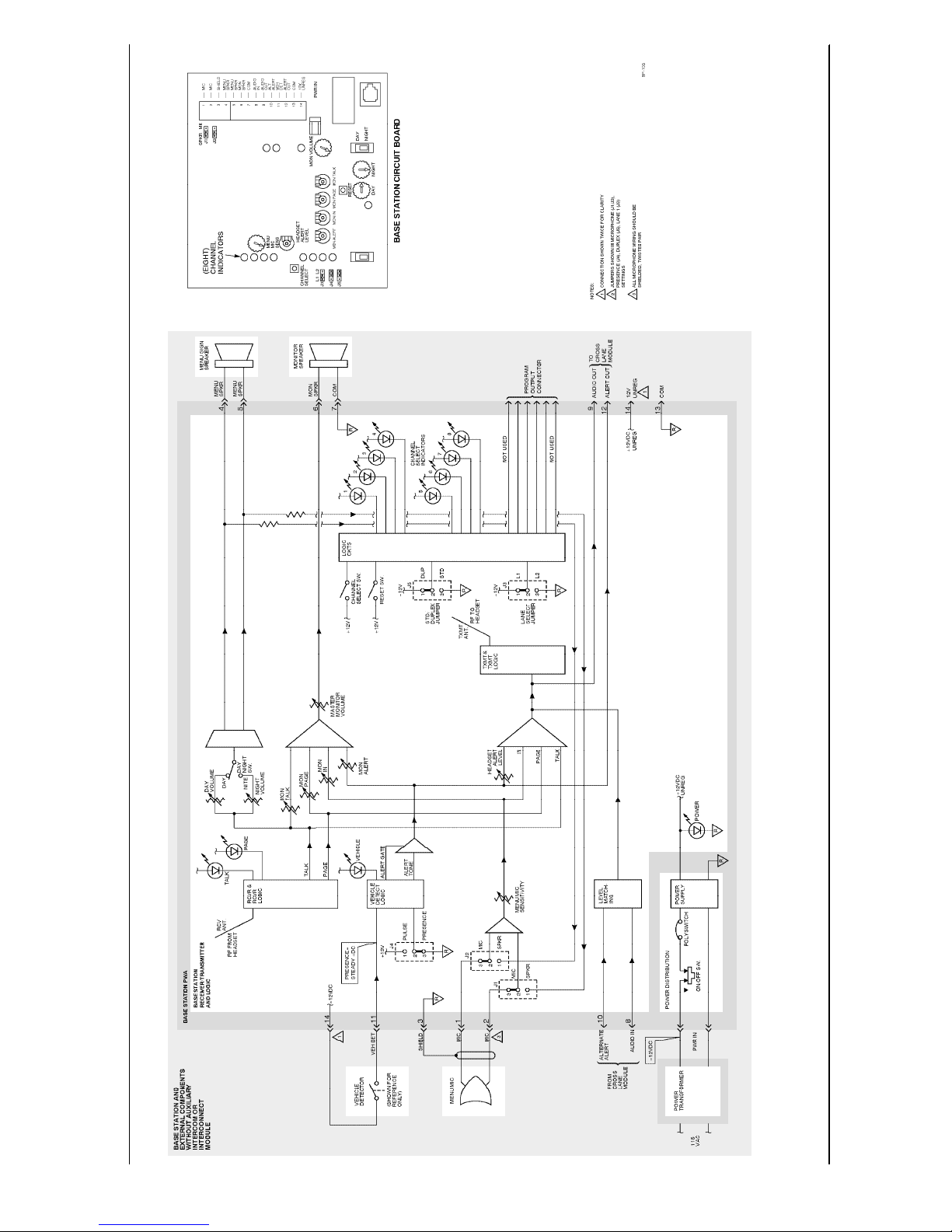
Base Station and External Components Diagram 1-8. . . . . . . . . . . . . . . . . . . . . . . . . . . . . . . . . . . . . . .
Interconnect Module 1-11. . . . . . . . . . . . . . . . . . . . . . . . . . . . . . . . . . . . . . . . . . . . . . . . . . . . . . . . . . . . .
On/Off DC 1-11. . . . . . . . . . . . . . . . . . . . . . . . . . . . . . . . . . . . . . . . . . . . . . . . . . . . . . . . . . . . . . . . .
Menu Microphone Signal Control 1-11. . . . . . . . . . . . . . . . . . . . . . . . . . . . . . . . . . . . . . . . . . . . . . . .
Menu Speaker Audio Control 1-11. . . . . . . . . . . . . . . . . . . . . . . . . . . . . . . . . . . . . . . . . . . . . . . . . . .
Monitor Speaker Audio Control 1-11. . . . . . . . . . . . . . . . . . . . . . . . . . . . . . . . . . . . . . . . . . . . . . . . .
Vehicle Detector Signal DC 1-11. . . . . . . . . . . . . . . . . . . . . . . . . . . . . . . . . . . . . . . . . . . . . . . . . . . . .
Interconnect Module Diagram 1-13. . . . . . . . . . . . . . . . . . . . . . . . . . . . . . . . . . . . . . . . . . . . . . . . . . . . . .
Section 2. Installation Instructions
Section 3. Replacement Parts and Service
Ordering Replacement Parts 3-1. . . . . . . . . . . . . . . . . . . . . . . . . . . . . . . . . . . . . . . . . . . . . . . . . . . . . . .
T echnicalService 3-1. . . . . . . . . . . . . . . . . . . . . . . . . . . . . . . . . . . . . . . . . . . . . . . . . . . . . . . . . . . . . . .
Section 1 - Base Station Assembly and Interconnect Module 3-2. . . . . . . . . . . . . . . . . . . . . . . . . . . . . .
Section 2 - Headset Assembly 3-4. . . . . . . . . . . . . . . . . . . . . . . . . . . . . . . . . . . . . . . . . . . . . . . . . . . . . .
Section 3 - 3-Slot Battery Charger Assembly 3-6. . . . . . . . . . . . . . . . . . . . . . . . . . . . . . . . . . . . . . . . . .
Section 4 - 6-Slot Battery Charger Assembly 3-7. . . . . . . . . . . . . . . . . . . . . . . . . . . . . . . . . . . . . . . . . .
Replacing the Headset Speaker 3-8. . . . . . . . . . . . . . . . . . . . . . . . . . . . . . . . . . . . . . . . . . . . . . . . . . . . .
Replacing the Mic Boom Assembly 3-11. . . . . . . . . . . . . . . . . . . . . . . . . . . . . . . . . . . . . . . . . . . . . . . . .
Replacing the Battery T erminals 3-12.. . . . . . . . . . . . . . . . . . . . . . . . . . . . . . . . . . . . . . . . . . . . . . . . . . .
Replacing the Battery Release Button Spring 3-13. . . . . . . . . . . . . . . . . . . . . . . . . . . . . . . . . . . . . . . . . .
Section 4. Troubleshooting
T roubleshootingGuide
Analyzing Batteries 4-1. . . . . . . . . . . . . . . . . . . . . . . . . . . . . . . . . . . . . . . . . . . . . . . . . . . . . . . . . . . . . .
DISCHARGE Test 4-1. . . . . . . . . . . . . . . . . . . . . . . . . . . . . . . . . . . . . . . . . . . . . . . . . . . . . . . . . . . .
CYCLE 1 Test 4-1. . . . . . . . . . . . . . . . . . . . . . . . . . . . . . . . . . . . . . . . . . . . . . . . . . . . . . . . . . . . . . .
CYCLE 2, CYCLE 3, and CYCLE 4 Tests 4-1. . . . . . . . . . . . . . . . . . . . . . . . . . . . . . . . . . . . . . . . .
Setup Procedures 4-2. . . . . . . . . . . . . . . . . . . . . . . . . . . . . . . . . . . . . . . . . . . . . . . . . . . . . . . . . . . . .
Initiating a Test 4-2. . . . . . . . . . . . . . . . . . . . . . . . . . . . . . . . . . . . . . . . . . . . . . . . . . . . . . . . . . . . . .
Interpreting Test Readings 4-2. . . . . . . . . . . . . . . . . . . . . . . . . . . . . . . . . . . . . . . . . . . . . . . . . . . . . .
Error Codes 4-2. . . . . . . . . . . . . . . . . . . . . . . . . . . . . . . . . . . . . . . . . . . . . . . . . . . . . . . . . . . . . . . . .
ii E 3M 2000 May
Page 6

Model C960 Headset Intercom System
Section 5. Operating and Installation Instructions
Model A121 Noise Reduction Module, 78-6912-0699--5
Model A125 Noise Reduction Module, 78--6912--0723--3
Models A200 and A201 Loop Detector , 78--6912--0712--6
Model A300 Audio Greeter, 78--6912--0717--5
Model C960 Operating Instructions
Cross-Lane Module Installation Instructions, 78--6912--0487-5
Headset Storage Rack Installation Instructions, 78--6912--0508-8
Duplex Menu Cable Installation Instructions, 78--6912--0509-6
3M Communications Bar Installation Instructions, 78--6912--0581-5
Five Inch Speaker and Mic Assembly Installation Instructions, 78--8050--8497-3
3.5-Inch Duplex Microphone Installation Instructions, 78--6912--0596-3
5--Inch Duplex Speaker Assembly, 78--6912--0530-2
Table of Contents
E 3M 2000 May
iii
Page 7

(Blank Page)
Model C960 Headset Intercom SystemTable of Contents
iv E 3M 2000 May
Page 8

Model C960 Headset Intercom System Operation andDiagrams
Introduction
The 3M Model C960 Headset Intercom System is a
wirelessintercomsystemdesigned forhigh reliability,
compactness, and ease of service. It is designed to
provide two-way, radio-frequency audio
communication in quick service drive-through
restaurants and convenience stores.
Thesystemcanbeprogrammedtooperateonanyone
of16differentchannelstoprovidehigh-qualityaudio
performance andreducethepossibilityofinterference
between neighboring wireless systems.
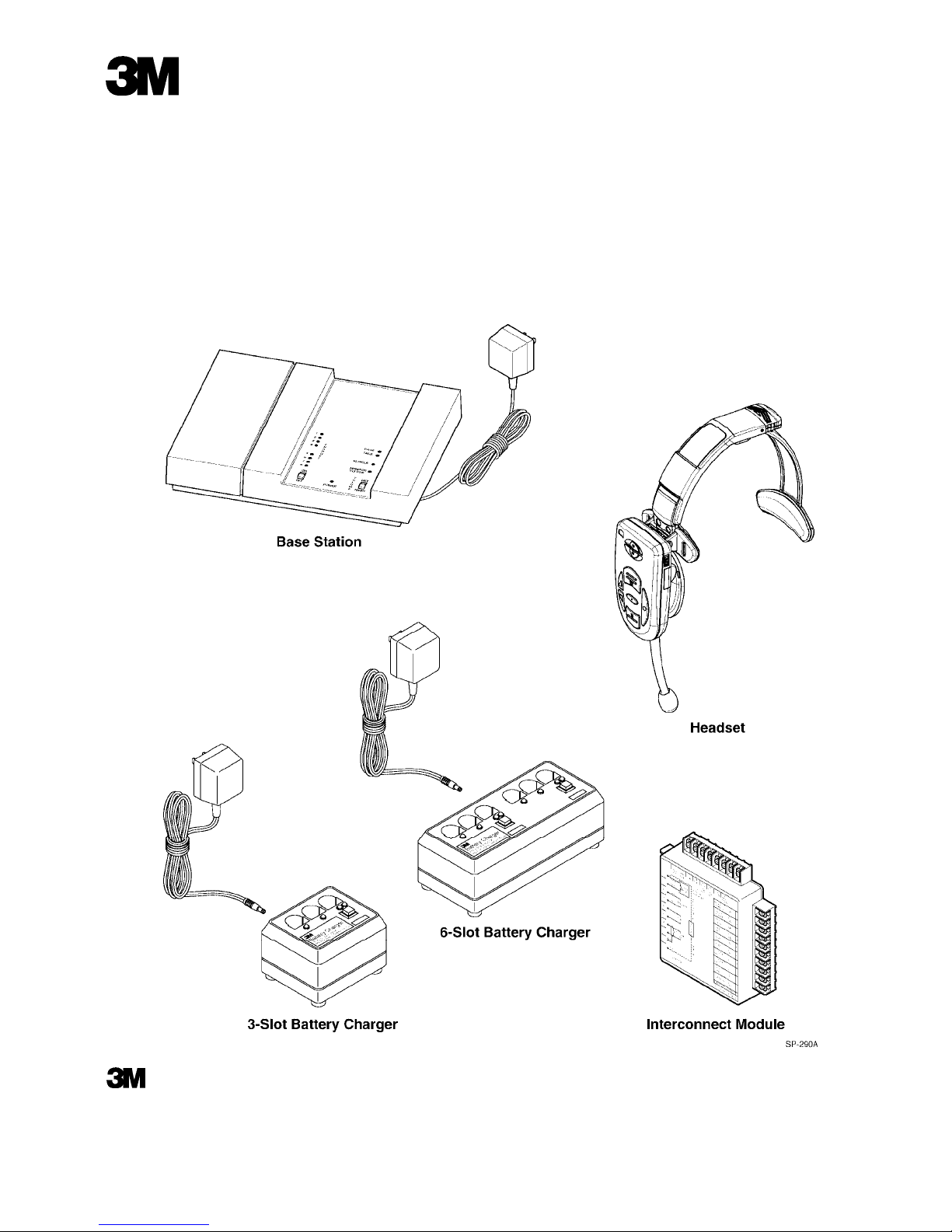
System Components
The number of components in a system varies
dependingonthesystemconfiguration.However,the
basestation,headset,andbattery chargerare common
to all system configurations.
Base Station
The wall-mounted base station contains logic and
analogcircuitsandrelatedsystemcontrols, areceiver
toreceivesignals transmittedfrom theheadsets,anda
transmitter to transmit signals to the headsets.
Headset
Theheadset is a wireless, battery-powered, two-way
radiousedbytheoperatortocommunicatewithmenu
signcustomersandwithotherstorepersonnelwho are
wearing headsets. The microphone and earpiece
enable the operator to transmit and receive spoken
communication and alert tones.
Theheadsetcanbeprogrammed tooperate onanyone
of16differentchannelstoprovidehigh-qualityaudio
performance andreducethepossibilityofinterference
between neighboring wireless systems.
The headset assembly has several field-replaceable
components. These components are detailed in
Section 3 of this manual (Replacement Parts and
Service).
Battery Charger
The battery charger charges headset batteries in
approximately 1.5 to 2 hours. The charger is
available in 3-slot and 6-slot versions.
Each battery charger has two field-replaceable
components:
S Charger Assembly
S T ransformerAssembly
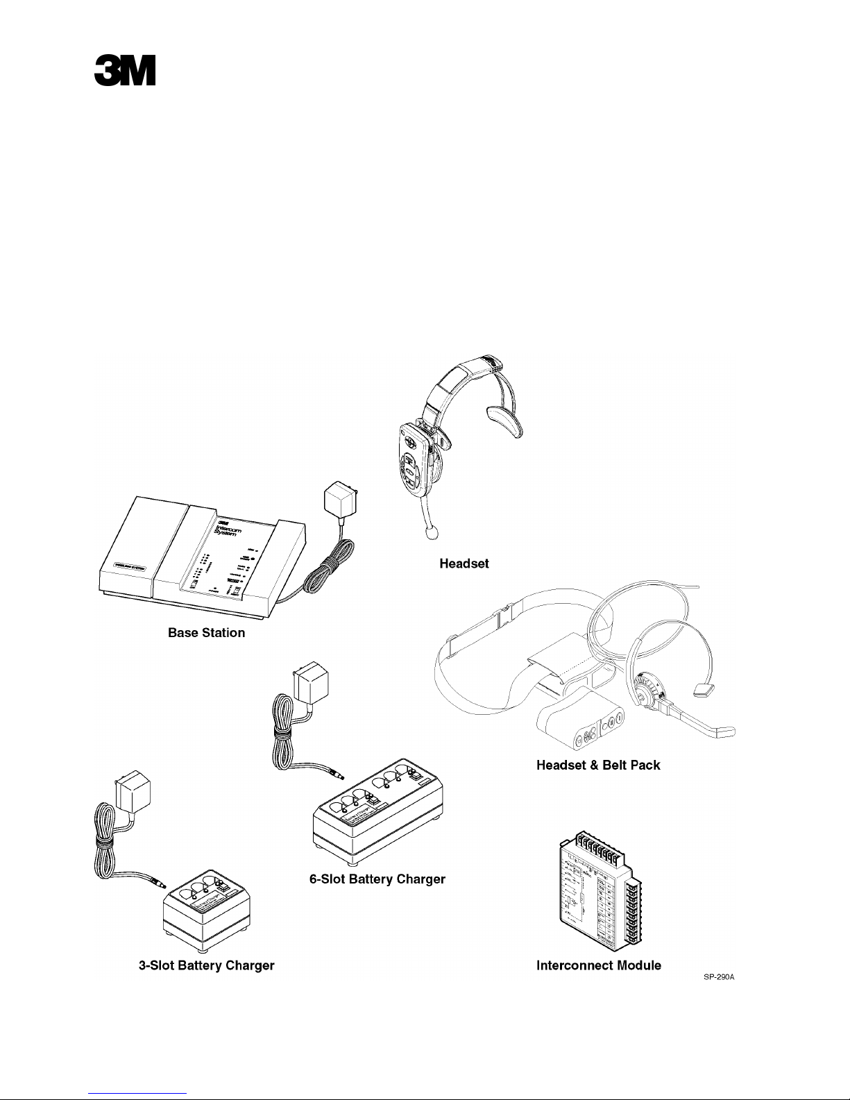
Speaker and Microphone Assemblies
Standard Systems
The 5-Inch Speaker and Mic Assembly is
recommended for use in standard communication
systems. It consists of a 5-inch, water-resistant,
eight-ohm cone speaker plus a special
weather-resistant dynamic microphone. It also
includes a mounting bracket for easy mounting in
menu signs, speaker posts and other applications.
Usingthis separatespeaker and microphone ensures
maximum sound quality.
Duplex Systems
The3.5-InchDuplexMicrophoneand5-InchDuplex
SpeakerAssembly arerecommendedforusein duplex
communication systems. The microphoneismounted
on a foam housing,which canbe cut to the required
size. The speaker is mounted in a metal housing.
Interconnect Module
This optional module provides a convenient
connection point for equipment such as speakers,
microphones, vehicle detectors, and auxiliary
intercoms.
Cross-Lane Module
This module is a required component for dual-lane
duplexcross-lanecommunicationsystems.Itenables
a single headset to operate two base stations.
Vehicle Alert System
The Model C960 is compatible with all 3M vehicle
detectors and those of most other manufacturers.
Thereare twotypes ofvehicledetectors, classifiedas
presence detectors or pulse detectors. Presence
detectors(suchasmagneticloopsorSODAR)provide
a signal for as long as a vehicle is present at the
detector. Pulse detectors, such as air hoses,provide
only a momentarysignal—signalling vehicle arrival
with no indication of whether or not the vehicle
remains at the detector station.
System Configurations
The system can be configured in one of five ways
dependingonthenumberofmenu signsatthefacility
and the type of communication desired.
1-1E 3M 2000 May
Page 9

ModelC960Headset IntercomSystemOperation and Diagrams
Single-Lane Standard Communication System
This system provides standard communication
(talk/listen) for facilitiesthat have one menu sign. It
consistsof onebase stationandoneormoreheadsets
and battery chargers.
Dual-Lane Standard Communication System
This system provides standard communication
(talk/listen)for facilitiesthat havetwo menu signs. It
consistsof twoindependent systems-- onededicated
tomenu sign 1 and the other dedicated to menusign
2. The headsets are programmed to work with one
systemor theother andare labeled accordingly (1or
2).
Single-Lane Duplex Communication System
This system provides duplex communication
(simultaneous talk/listen) for facilities that have one
menusign. Itconsists ofone base station and one or
more headsets and battery chargers.
Dual-Lane Duplex Communication System
This system provides duplex communication
(simultaneous talk/listen) for facilities that have two
menu signs. Itconsists oftwo base stations and two
or more headsets and battery chargers.
Cross-Lane Communication System
This system provides duplex communication
(simultaneous talk/listen) for facilities that have two
menusigns. Itconsistsoftwoduplexsystemsthatare
connected to a cross-lanemodule. The headsets are
programmed for either lane 1 or lane 2.
During off-peak hours, the cross-lane module is
turned on to link the two systems and enable one
operatorto talkto customersat menu sign 1 or menu
sign 2 or with other headset operators.
Duringpeakhours,the cross-lanemoduleisturnedoff
to separate the systems. Withthe cross-lane module
off, one system is dedicated to menu sign 1 and the
otherto menusign 2. Menusign 1 operators cantalk
to customers at menu sign 1 or with other headset
operators. Menu sign 2 operators can talk to
customers at menu sign 2 or with other headset
operators.
Operating Theory
The 3M Model C960 Headset Intercom System has
two basic functions. First, it processes vehicle alert
signals that are supplied by a hard-wired vehicle
detection system. Second, it transmits and receives
radiosignals toprovide oneor more of the following
types of audio communication:
S T alk/listencommunication
S T alklock communication
S Page communication
S Page monitor communication
S Cross-lane talk/listen communication
Processing Vehicle Alert Signals
The Model C960 is compatible with all 3M vehicle
detectorsandthoseofmostothermanufacturers. The
vehicle alert system provides a signal to the base
station to indicate a customer is present at the menu
sign.
There are two types of vehicle detectors. Presence
detectors (such as magnetic loops or SODAR)
provide a signal for as long as a vehicle is presentat
the detector. Pulse detectors, such as air hoses,
provideonlyamomentarysignal—signallingvehicle
arrival with no indication of whether or not the
vehicle remains at the detector station.
S Ifa presencedetector isused, menu sign audio is
turnedoffautomaticallywhenthevehicleleaves.
S If a pulse detector is used, menu sign audio is
silencedbypressingandreleasinga headsetpage
switch.
When a vehicle detection signal is presented to the
base station, the base station broadcasts a repeating
alert tone to all headsets. The alert tone continues
untilthe talkswitch [onan active headset] ispressed.
Transmitting and Receiving
The transmitting and receiving functions are
accomplished by two separate sets of radio
transmitters and receivers. One set is located in the
headset and the other in the base station.
1-2 E 3M 2000 May
Page 10

Model C960 Headset Intercom System Operation andDiagrams
Theheadset receivesmicrophoneaudiosignalsfrom
the base station on frequency B and transmits both
audiosignals andcontrol toneson frequencyA. The
control tones are above the audible range, and
functiontoturnthebasestation receiverONtoenable
reception of the audio signal from the headset
microphone. Because thecontroltonesareabovethe
audible range, audible tones from devices such as
telephones, pagers, and radios will not interfere.
The base station transmits on frequency B and
receives on frequency A. The receiver in the base
station operates above the audible frequency range.
While it receives the high-frequency control tones
from the headset, it is not affected by audible tones
from devices such as telephones, pages, and radios.
The transmitter in the base station is always
transmitting a “no signal” transmitter carrier, even
when there is no microphone audio from the menu
sign or headset operator being broadcast. This “no
signal“ carrieriscontinuallybroadcasttoand received
by all headset receivers. It serves to block out other
radio-frequency signals or noises from headset
receivers.
Similarly,theheadset receiverisalwaysONtoenable
the listen mode. The headset transmitter turns ON
only when a talk or page switch is pressed.
S Personnel wearing headsets that are operating in
the talk/listen mode.
S People near the optional monitor speaker.
Talk/Listen Communication
Headset to Menu Sign
After the vehicle detection signal is presented to the
base station, the base station broadcasts a repeating
alert tone to all active headsets.
Theheadsetoperatorpressesandholdsthetalkbutton
to acknowledge the customer at the menu sign and
cancel the alert tone. When the headset operator
speaks into the microphone, the headset generates a
talkcontrol toneandaddsittothemicrophoneaudio.
Themicrophone audioand talkcontrol tone are then
transmittedto thebase station. Thetalk controltone
turns the base station receiver ON , enabling it to
receive the microphone audio.
n Note
The talk control tone is above the audible
frequency range, and is used to prevent the base
station receiver from receivingsignals fromother
devices(telephones, pagers,etc.) thatmight be on
the same frequency.
Instandard communicationsystems, theoutputfrom
the headset receiver is muted when the headset
transmitter is ON. This provides standard
communication (talk or listen).
In duplex communication systems, the outputfrom
theheadset receiveris enabled(not muted) when the
headset transmitter is ON. This provides duplex
communication (simultaneous talk and listen).
The two sets of transmitters and receivers work
togetherto provideaudio communicationbetween the
customerat the menu sign and the headset operators
insidethedrive-throughrestaurantorbetween twoor
more headset operators.
All audio transmitted by a headset during talk
operation is heard by:
S Menu sign customers.
S Personnel wearing active headsets.
S People near the optional monitor speaker.
All audio from the menu sign is heard by:
Whenthebasestationreceivesthemicrophoneaudio
signal, it re-transmits it to all headset receivers. The
same microphone audio signal is also routed to the
menu speaker amplifier and the monitor speaker
amplifier.
The menu speaker amplifier routes the amplified
microphoneaudio throughwire tothe menuspeaker
where it can beheard bythe customer. The monitor
speaker amplifier routes the amplified microphone
audio through wire to an optional monitor speaker
(typicallylocated inthe kitchenarea) where it can be
heard by anyone in close proximity to the speaker.
n Note
The menu sign audiois not turned ON unlessthe
base station receives a talk control tone from the
headset. However, the the monitor amplifier is
always turned ON.
1-3E 3M 2000 May
Page 11

ModelC960Headset IntercomSystemOperation and Diagrams
Menu Sign to Headset
Whenthe customerat themenu sign speaks, audio is
detectedbyamicrophoneandsentthroughwiretothe
transmitter and the monitor amplifier in the base
station.
Thetransmitter transmitsthe microphoneaudio toall
headset receivers. The monitor amplifier routes the
samemicrophone audiothrough wireto theoptional
monitor speaker.
n Note
Personnelwearing headsetsthat areset tomonitor
only page communications will not hear talk
communications. If the headsets is in the Page
Monitor Mode, the “talk” audio output to the
headset speaker is muted.
Talk Lock Mode
Thetalklockmodeisusedtooperate“handsfree.” In
this mode, the headset automatically switches from
standby to talk/listen when a customeris detected at
the menu sign. The headset automatically switches
back to standby when the customer leaves the menu
sign. Thismode isonlyavailablewithduplexsystem
configurations.
Page Mode
When the headset page button is pressed, system
operationis identicalto talkoperation except for two
things:
S The talk control tone is not broadcast, so the
menu sign amplifier is not turned on, muting
menu sign audio.
headsettransmitteristurnedONonlywhenitreceives
a page control tone. T alktransmissions from other
headsets or audio from the menu sign are not heard.
Cross-Lane Talk/Listen Mode
Thecross-lane talk/listen mode is available only in a
dual-lane duplex cross-lane system. The cross-lane
moduleinthis systemenablesthemenusignoperator
to selectively communicate (talk and listen) to
customers in either lane 1 or lane 2.
W iththeT1 (TalkLane1)switchpressed,theheadset
transmitter/receiver switches to the lane 1 channel
frequencies,enabling thelane1basestation andlane
1 communications.
W iththeT2 (TalkLane2)switchpressed,theheadset
transmitter/receiver switches to the lane 2 channel
frequencies,enabling thelane2basestation andlane
2 communications.
Monitor Amplifier and Speaker
A one-watt, single-ended monitor amplifier in the
base station powers [an optional] speaker which is
capable of reproducing the following signals:
S T alk audio(communicationsto themenu speaker)
S Listen audio (communication from the menu
speaker)
S Page audio (internal store communications)
S Vehicle alert tone
Separate volume controls adjust the level of each
signal to achieve the desired signal balance. In
addition, there is a master volume control which
adjusts the overall volume of the monitor speaker.
S A page control tone is sent from the headset,
turning on the base station transmitter. The
transmitterrebroadcasts thistone toturn ON any
headsetsthat arein thepage monitor mode. Any
audio detected by the headset microphone is
transmitted to the base station where it is
received,transmittedtootherheadsetsand sentto
the monitor speaker amplifier.
Page Monitor Mode
The page monitor mode allows headset operators to
hearonly pagecommunication. Inthe pagemonitor
mode,talk audiooutputtotheheadsetismuted.Only
internal page communication is heard because the
1-4 E 3M 2000 May
Headset Components
n Note
The receiver/transmitter and logic circuitry
contained in the C960 headset housing is both
proprietary and non-field repairable.
The headset assembly has several field-replaceable
components. These components are detailed in
Section 3 of this manual (Replacement Parts and
Service).
The major components are as follows:
Page 12

Model C960 Headset Intercom System Operation andDiagrams
S Rechargeable Battery
S Headband
S Microphone Boom Assembly
S Speaker Assembly
Rechargeable Battery
Thenickel metalhydride batteryprovides DC power
for the headset circuitry.
Headband
Theheadbandconsistsoftwointerlockingassemblies
that provide adjustments for headband width and
headband size. Both assemblies are replaceable.
Microphone Boom Assembly
The boom/earpiece assembly includes an electret
microphone and a speaker-driven earpiece. It is
replaceable as a separate unit.
Speaker Assembly
The speaker assembly is housed between the inner
andouter casesand is replaceable as a separate unit.
1-5E 3M 2000 May
Page 13

ModelC960Headset IntercomSystemOperation and Diagrams
Base Station
n Note
Receiver/transmitter and logic circuitry contained
in the C960 headset intercom base station is both
proprietary and non-field repairable. For this
reason, the accompanying base station diagram
provides no circuitcomponent detail. Onlythose
details that assist fault isolation (such as
connections,configurationjumpers,audiocontrol
circuits,replaceable componentsandinput/output
functions) are shown.
DC Power
DC power for the base station circuits and external
components is provided as follows:
Aself-containedDCpowertransformer,connectedto
120VAC, provides unregulated +12VDC to the base
station power input jack. The +12VDCis turned on
oroffby aslideswitchlocatedonthefrontofthebase
station. The unregulated +DC is routed through a
protective polyswitch (circuit breaker) to circuit
components and a voltage regulator (called power
supply in the diagram). If an overcurrent condition
causesthe polyswitchto open,it automaticallyresets
after power is removed.
The unregulated +12VDC is used by the vehicle
detectorto providea +DCvehicle detect signal tothe
basestationvehicledetectcircuits. Ifaninterconnect
module is used in the system, unregulated +DC is
providedto energizethe interconnectmodulerelays.
Talk/Page Input
T alkand pagevoicecommunicationstransmittedfrom
the headset are received along with their
accompanying “talk” or “page” control tones.
Received talk communications are routed by the
RCVR & RCVR LOGIC as follows:
S Through the transmit amplifier to the TXMT &
TXMT LOGIC for transmission to all headset
receiversand tooutput connectorpin 9 for usein
cross-lane applications
Received page communications are routed by the
RCVR & RCVR LOGIC as follows:
S T othe monitor speaker amplifier via the MON
P AGEvolumecontrol, throughthe amplifierand
theMasterMonitorVolumecontrolto themonitor
speaker
S Through the transmit amplifier to the TXMT &
TXMT LOGIC for transmission to all headset
receivers,andtooutputconnectorpin9forusein
cross-lane applications
Vehicle Detector Input
Upon detection of a vehicle, the vehicle detector
signal will be a steady DC or a short-duration DC
pulsedepending onwhether the vehicle detector is a
“presence”or “pulse”type detector. Uponreceiptof
the vehicle detect signal, the VEHICLE DETECT
LOGICcircuit emitsalert tones. Thesealerttonesare
routed as follows:
S T othe monitor speaker amplifier via the MON
ALERT volume control, through the monitor
speakeramplifierandtheMasterMonitorvolume
control to the monitor speaker
S T othe transmit amplifier via the Headset Alert
Levelcontrol, throughtheamplifiertotheTXMT
& TXMT LOGIC for transmission to all headset
receivers
S T ooutput connector pin 12 foruse in cross-lane
applications
S T othe menu sign speaker amplifier via the
DAY/NIGHTvolume controlsand DAY/NIGHT
switch, through the amplifier to the menu sign
S T othe monitor speaker amplifier via the MON
T ALKvolumecontrol, through the amplifierand
theMasterMonitorVolumecontrolto themonitor
speaker
1-6 E 3M 2000 May
Page 14

Model C960 Headset Intercom System Operation andDiagrams
n Note
The vehicle detect PULSE/PRESENCE jumper J4
must be set appropriately and its setting
programmedinto thebase stationlogic forcorrect
vehicle detection and alert tones to occur.For
further explanation of vehicle detect alert tones,
refer to the Vehicle Alert System, The vehicle
detect PULSE/PRESENCE jumper J4 must be set
appropriately and its settingprogrammed intothe
basestation logicfor correctvehicle detectionand
alert tones to occur.For further explanation of
vehicle detect alert tones, refer to the paragraphs
titled Vehicle Alert System and Vehicle Detector
Input in this section.
Menu Mic Input
Audiofromthemenusignmaycomefromoneoftwo
sources: a combination speaker/microphone (the
MENU SIGN SPEAKER) or a separate dynamic
microphone (the MENU MIC). The MIC/SPKR
jumpersJ1 andJ2mustbesetaccordingly;bothmust
beset tothe MICposition ifa separate outside mic is
used, to the SPKR position if a combination outside
speaker/mic (OSM) is used. Depending on jumper
positions, mic input is routed to the mic amplifier,
through the amplifier and its Menu Mic Sensitivity
control and then:
S T othemonitor speakeramplifier viathe MONIN
volume control, through the monitor speaker
amplifierand theMaster Monitorvolumecontrol
to the monitor speaker
S Through the transmit amplifier to the TXMT
&TXMT LOGIC for transmission to all headset
receivers,andtooutputconnectorpin9forusein
cross-lane applications
Base Station Configuration Jumpers and
Switches
Configuration Jumpers
Jumpers J1 and J2 are used to configure the base
station for use with either a separate outside
microphone or a combination outside speaker/mic
(OSM). Unlike jumpers J3, J4 and J5 which affect
logic input levels, jumpers J1 and J2 simply switch
the microphone amplifier inputs to either the
microphoneorOSM. Setbothjumperstojumperpins
2 and 3 for use with a separate outside mic, or to
jumper pins 1 and 2 for a combination speaker/mic
(OSM).
JumperJ3is usedtoconfigurethebasestationforuse
inacross-lane,dual-lanecommunicationssystem. In
sucha system,one basestation must be set for lane 1
frequency communications, the other base station
must be set for lane 2 frequency communications.
JumperJ3pins1and2(forcingtherelatedlogicinput
high)forlane1configuration. JumperJ3pins2and3
(forcing the related logic input low) for lane 2
configuration. WheneverjumperJ3 ischanged, you
mustpress thebase stationRESETswitch toprogram
the new jumper setting into the base station
microprocessor.
n Note
It may also be necessary to re-program system
headsets, depending on system configuration.
RefertotheC960InstallationInstructions formore
information.
JumperJ4is usedtoconfigurethebasestationforuse
witheither apresencetypevehicledetectororapulse
typevehicledetector. JumperJ4pins 1and2(forcing
the related logic input high) for a presence type
detector. JumperJ4pins 2and 3 (forcing the related
logicinput low)for apulse typedetector. Whenever
jumperJ4 ischanged,youmustpressthebasestation
RESETswitchtoprogramthenewjumpersettinginto
the base station microprocessor.
JumperJ5 isusedtoconfigurethe basestation sothat
itcan inturn,programtheheadsetsforstandard(talk,
then listen, then talk etc.) communications or for
duplex (simultaneous talk and listen)
communications. Duringstandardcommunications,
headset receiver output is muted during talk
transmissions. During duplex communications,
headset receiver output is not muted during talk
transmissions. The headset receiver mute/not mute
(standard/duplex) command is sent to the headset
logic during headset programming—determined by
the jumper J5 setting. Whenever Jumper J5 is
1-7E 3M 2000 May
Page 15

changed, you must press the base station RESET
switch to program the new jumper setting into the
base station microprocessor.
n Note
When jumper J5 is changed, you must also
reprogramthe systemheadsets. Referto theC960
Installation Instructions for more information.
Configuration Switches
RESET SWITCH: Very briefly, actuation of the
RESET SWITCH clears logic inputs of their
establishedlevels andlatches thelogic inputs at their
new levels.
CHANNELSELECT SWITCH: TheC960 systemis
capable of operating on eight different channels for
each of two lanes. This provides a total of 16
operating channels since each system may be
designated as a lane 1 or lane 2 system. Each
operating channel is comprised of a “set” of two
frequencies, one for receiving, one for transmitting.
Thechannel frequenciesare preprogrammedin both
the base station and headset microprocessors. Each
actuationof theCHANNELSELECTswitchprompts
thebasestationmicroprocessortoadvancetothenext
available channel. After a new channel is selected,
you must reprogram all system headsets to the new
channel. (Headsetscanoperateonlyonlane1orlane
2 channels unless they are used with an accessory
cross-lanemodule.) Formoreinformationon channel
selection and reprogrammning, refer to the C960
Installation Instructions.
ModelC960Headset IntercomSystemOperation and Diagrams
1-8 E 3M 2000 May
Page 16
Model C960 Headset Intercom System
Operation and Diagrams
1-9
E 3M 2000 May
Base Station and External Components Diagram
Page 17

Model C960 Headset Intercom System
Operation and Diagrams
1-10
E 3M 2000 May
(Blank Page)
Page 18

Model C960 Headset Intercom System
Operation andDiagrams
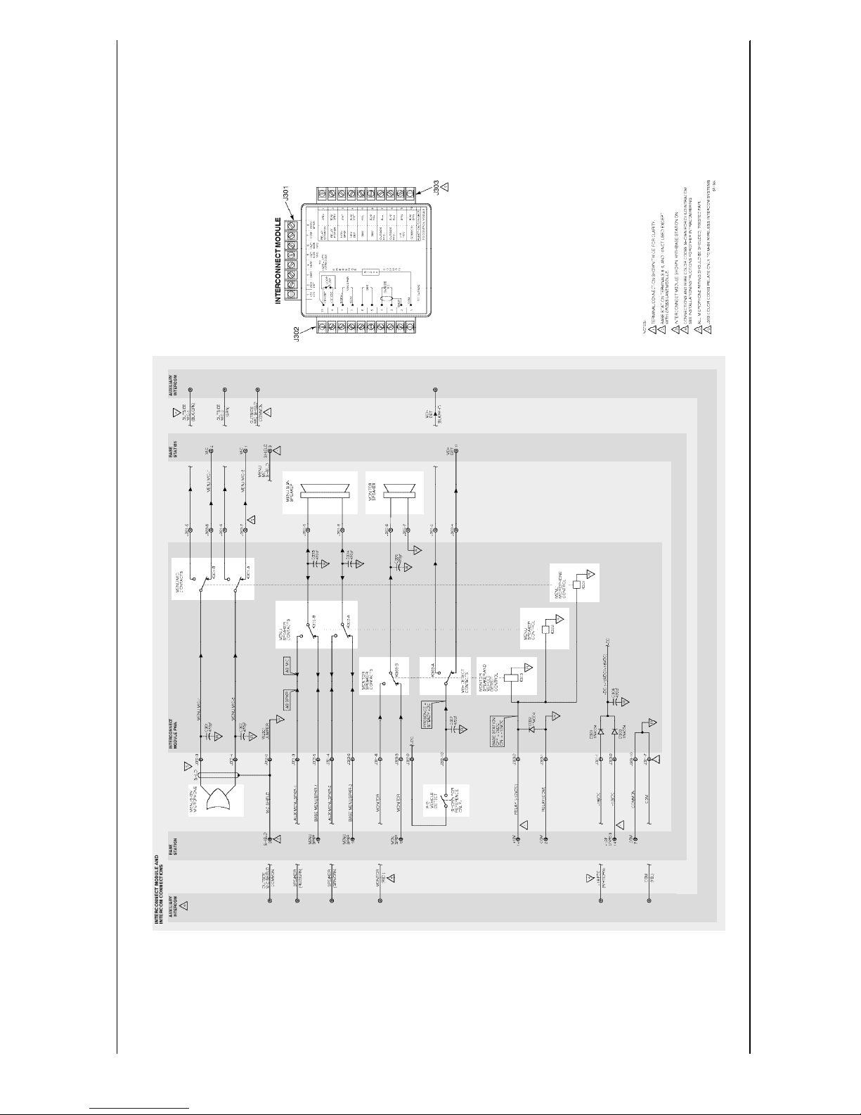
Interconnect Module
An interconnect module is needed when a C960
Headset Intercom system includes an auxiliary
intercomtoprovidecontinuedcommunicationswhen
the primary intercom needs service.
The auxiliary intercom may be a conventional,
hard-wiredintercom oritmaybeasecondC960base
station.
Externalsystemcomponents (speakers,microphone,
vehicle detector) connect to interconnect module
connector J302. Base station inputs and outputs
(power, common, menu mic, menu speaker, vehicle
detector) connect to interconnect module connector
J303. Auxiliary intercom (or second base station)
inputs and outputs connect to interconnect module
connector J301.
On/Off DC
In the interconnect module schematic diagram, the
interconnect module is shown in its “on” state, with
relays energized.
On/Offcontroloftheinterconnectmoduleisprovided
by (the presence or absence of) +12VDC from the
(primary) base station. W ithbase station +12VDC
present (via J303 pins 1 and 2), relays K301, K302
and K303energizetoswitch microphone,speakerand
vehicledetect signalsto/from thebase station. Ifthe
basestation-provided DCis notpresent (basestation
turnedoff),relaysK301,K302andK303 de-energize
to the switch the same signals to/from the auxiliary
intercom.
Menu Microphone Signal Control
Relay contacts K301-A and K301-B control
distribution of the menu mic signal(s). W ith relay
K301 energized, the menu mic is connected to the
base station inputs. W ithRelay K301 de-energized,
themenu micis connected to the auxiliary intercom.
Menu Speaker Audio Control
Relay contacts K302-A and K302-B control
distribution of the menu speaker audio. W ith relay
K302energized,themenuspeakerisconnectedtothe
basestation. W ith relayK302de-energized,themenu
speaker is connected to the auxiliary intercom.
Monitor Speaker Audio Control
Relay contactsK303-Bcontroldistributionofmonitor
speakeraudio. W ithrelayK303 energized, the drive
side of the monitor speaker is connected to the
monitorspeakeroutputofthebase station. With relay
K303 de-energized, the drive side of the monitor
speakerisconnected tothemonitorspeakeroutputof
the auxiliary intercom. Monitorspeaker commonis
not switched.
Vehicle Detector Signal DC
Whilethe vehicledetector ispoweredseparately (ifit
isa “presence”typedetector),vehicledetectorsignal
DC is always provided by both the base station and
the auxiliary intercom. This vehicle detector signal
DC is available at interconnect module connector
J302-9.
Avehicle detectorsignal DCof +12VDC isprovided
by the base station at J303pins 9 and 10. A vehicle
detector signal DC of +18VDC is provided by the
auxiliary intercom at J301 pins 1 and 7.
Ifboth theauxiliary intercomand thebasestationare
ON, the vehicle detector signal will always be
+18VDC because the auxiliary intercom’s +18VDC
will take precedence over the +12VDC supplied by
the base station. (Isolation of the twoDC sourcesis
provided by interconnect module diodes D301 and
D303.) If only the base station is ON, the vehicle
detector signal DC will be +12VDC.
1-11E 3M 2000 May
Page 19

(Blank Page)
Model C960 Headset Intercom SystemOperation and Diagrams
1-12 E 3M 2000 May
Page 20
Model C960 Headset Intercom System
Operation and Diagrams
1-13
E 3M 2000 May
Interconnect Module Diagram
Page 21

Model C960 Headset Intercom System
Operation and Diagrams
1-14
E 3M 2000 May
(Blank Page)
Page 22
Headset Intercom Systems
Model C960/C860
Installation Instructions
Page 23

Page 24

i
Table of Contents
Typical Single Lane Installation............................................................................................................ 1
Battery Charger ................................................................................................................................... 2
Speaker and Microphone Assemblies.................................................................................................... 3
Standard Systems........................................................................................................................... 3
Duplex Systems ............................................................................................................................. 3
Face–to–Face Type Duplex Systems............................................................................................... 3
Base Station ........................................................................................................................................ 3
Interconnect Module (Optional)............................................................................................................ 4
Connecting the Base Station Directly to Components............................................................................. 5
Connecting the Base Station to Components Using the Optional Interconnect Module.............................. 6
Connecting the Auxiliary Intercom (Optional)....................................................................................... 8
Dual Lane System Installation .............................................................................................................. 9
Cross Lane System Installation............................................................................................................. 10
System Configurations and Function Jumper Settings............................................................................. 14
Standard Operation – Single Lane System (One Base Station) .......................................................... 14
Standard Operation – Dual Lane System (Two Base Stations)........................................................... 14
Duplex Operation – Single Lane System (One Base Station)............................................................. 15
Duplex Operation – Dual Lane System (Two Base Stations)............................................................. 15
Channel Selection................................................................................................................................ 16
Setting Audio Levels............................................................................................................................ 17
Duplex Systems Only..................................................................................................................... 18
Duplex and Standard Systems......................................................................................................... 18
Alert Tone Level............................................................................................................................ 18
Monitor Speaker Volume Levels............................................................................................... 19
Standard Systems Only .................................................................................................................. 19
Listen Level (Menu Sign Microphone Sensitivity) ..................................................................... 19
Menu Sign Talk Volume Level................................................................................................. 20
Circuit Board Jumpers, Adjustment Controls, Indicators and Switches .................................................... 21
Jumpers......................................................................................................................................... 19
Adjustment Controls...................................................................................................................... 22
Indicators...................................................................................................................................... 22
Switches (etc.)............................................................................................................................... 22
Connectors.................................................................................................................................... 22
Finishing Up........................................................................................................................................ 23
Troubleshooting Audio Feedback.......................................................................................................... 23
Technical Assistance............................................................................................................................ 23
Page 25

ii
Illustrations
Figure 1. Typical Installation............................................................................................................... 1
Figure 2. Battery Chargers (3–Slot and 6–Slot Versions)....................................................................... 2
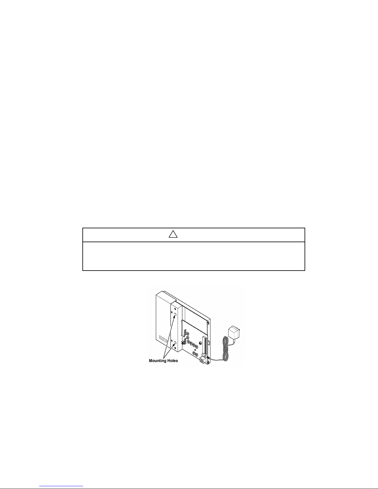
Figure 3. Base Station Mounting Holes................................................................................................ 3
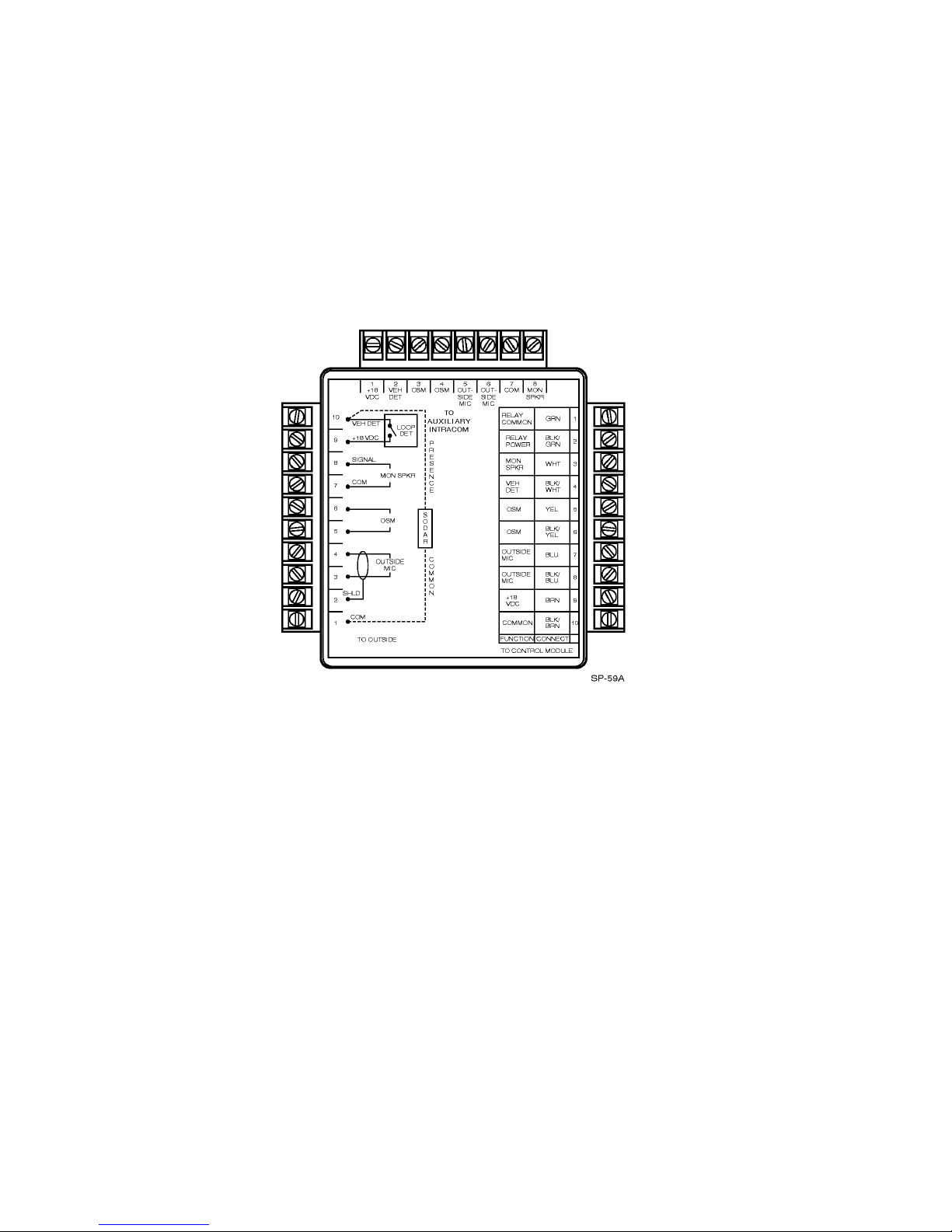
Figure 4. Interconnect Module............................................................................................................. 4
Figure 5. Direct Base Station–to–Component Connections.................................................................... 5
Figure 6. Base Station – Interconnect Module Connections.................................................................... 6
Figure 7. Connecting Components to the Interconnect Module .............................................................. 7
Figure 8. D–15D (M478 DA) Connections........................................................................................... 8
Figure 9. D–15B and D–15C (M478 BA and CA) Connections.............................................................. 8
Figure 10. D–30 Connections .............................................................................................................. 9
Figure 11. Cross–Lane Wiring Diagram............................................................................................... 11
Figure 12. Removing the Half–Cover from the Base Station.................................................................. 16
Figure 13. Base Station Circuit Board .................................................................................................. 17
Figure 14. Base Station Circuit Board .................................................................................................. 21
Page 26
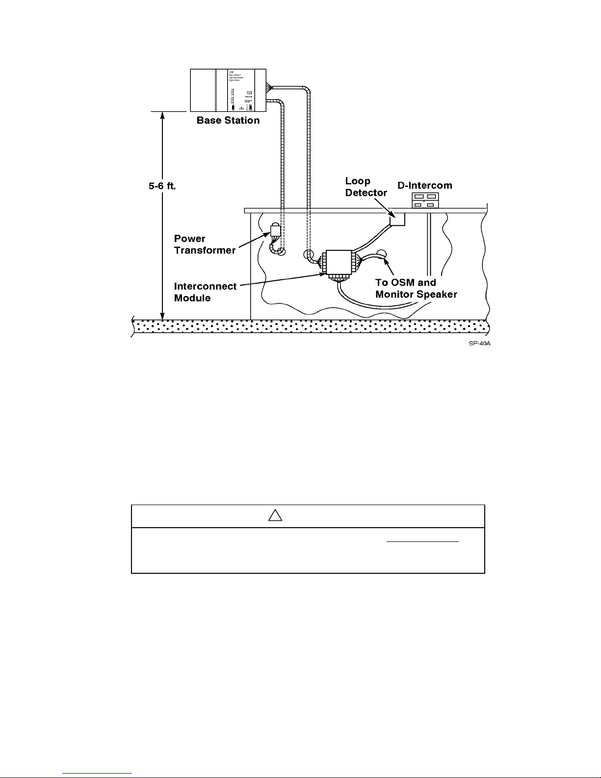
Typical Single Lane Installation
!
same jacket unless specially designed for duplex such as 3M 78–8095–0180–8.
Figure 1. Typical Installation
Material Required (not supplied)
• 3/4–inch conduit (metal or plastic) – 2 pieces 4–5 feet in length
• conduit clamps
• assortment of sheet metal screws
• two sets of 18–gauge, twisted–pair (two wires each set) audio cable, sufficient in length to connect the
speaker and microphone assembly (in the menu sign) to the interconnect module or base station.
Important
The twisted–pair of wires for the microphone connection must be shielded for
proper operation. In duplex systems, microphone and speaker cannot be in the
• sufficient twisted–pair sets of audio cable to connect other components such as monitor speaker, vehicle
detection device, etc.
1
Page 27

2
Battery Charger
Install the battery charger and begin charging the batteries before you install any other components.
Install the battery charger in a clean, dry environment. An office location is best.
The battery charger may be placed on a flat surface such as a table, desk, etc., or it can be fastened to a wall using
the optional wall–mount kit.
Plug the power supply transformer into a 120–Volt wall outlet and then plug the transformer cord into the
connector in the end of the battery charger. The three green lights on the battery charger will turn on.
To charge a battery, plug it into the charger as shown in Figure 2. Observe the charging status indicator next to
the battery:
• The indicator lights RED to indicate the battery is charging.
• The indicator lights GREEN to indicate the battery is fully charged.
• The indicator lights ORANGE to indicate the battery is defective.
ü Note
Discharged batteries require 1–1/2 to 2 hours to charge.
When the battery voltage becomes too low, a short, low volume tone, occurring at seven–second intervals is
heard in the headset. This repeating tone continues for two minutes. After the two–minute interval, the headset
automatically turns off to prevent battery damage.
Figure 2. Battery Chargers (3–Slot and 6–Slot Versions)
Page 28
Speaker and Microphone Assemblies
!
Standard Systems
For standard systems, install the Deluxe 5–Inch Speaker and Microphone Assembly, Part Number 78–6911–
1545–1. Refer to the installation instructions packaged with the assembly.
Duplex Systems
For duplex systems, install the 3.5–Inch Duplex Microphone (with foam housing), Part Number 78–6911–4476–
6 and the 5–Inch Metal Speaker Assembly, Part Number 78–6911–4411–3. Refer to the installation instructions
packaged with the assemblies.
Face–to–Face Type Duplex Systems
The 3M Communications Bar, Part Number 78–6911–4451–9 contains the Duplex Speaker and Microphone
listed above. Refer to the installation instructions that are packaged with the assembly.
Base Station
1. For proper system operation, locate the base station module:
• 5 to 6 feet above the floor
• at least 10 feet from the cashier/drive–thru window
• At least 3 feet from large metal objects such as refrigerators, ranges, coolers, etc., and other metal or
electrical devices.
Important
Do not mount base station under steel countertops, within 3 feet of
coolers/refrigerators/ranges or in areas where it will be obscured by steel
doors, walls, etc. as this will cause operational problems.
2. Mount the base station using the included screws and anchors. (See Figure 3.)
Figure 3. Base Station Mounting Holes
3. Install conduit and cable clamps as necessary.
4. Feed the cables for speaker, microphone, vehicle detect and monitor speaker (if used) through the conduit
down to the interconnect module or base station. (See Figure 1.)
5. Feed the transformer cable from the outlet to the base station. (See Figure 1.)
Keep the transformer cable at least 6 inches from the left half of the base station. This half contains sensitive
radio components which will be affected if the cable is too close.
3
Page 29
4
Interconnect Module (Optional)
1. Install the interconnect module in an “out of the way” location, near the wiring for the auxiliary intercom,
vehicle detector, etc. (Under a counter is desirable.)
2. To fasten the interconnect module in position:
a. Remove the backing from the adhesive hook and loop fastener material on the rear of the module.
b. Orient the module to provide the most convenient wire connection arrangement.
c. Press the adhesive surface of the hook and loop fastener material against a flat, smooth surface.
The module is now removable for wiring and if needed, future servicing.
Figure 4. Interconnect Module
Page 30
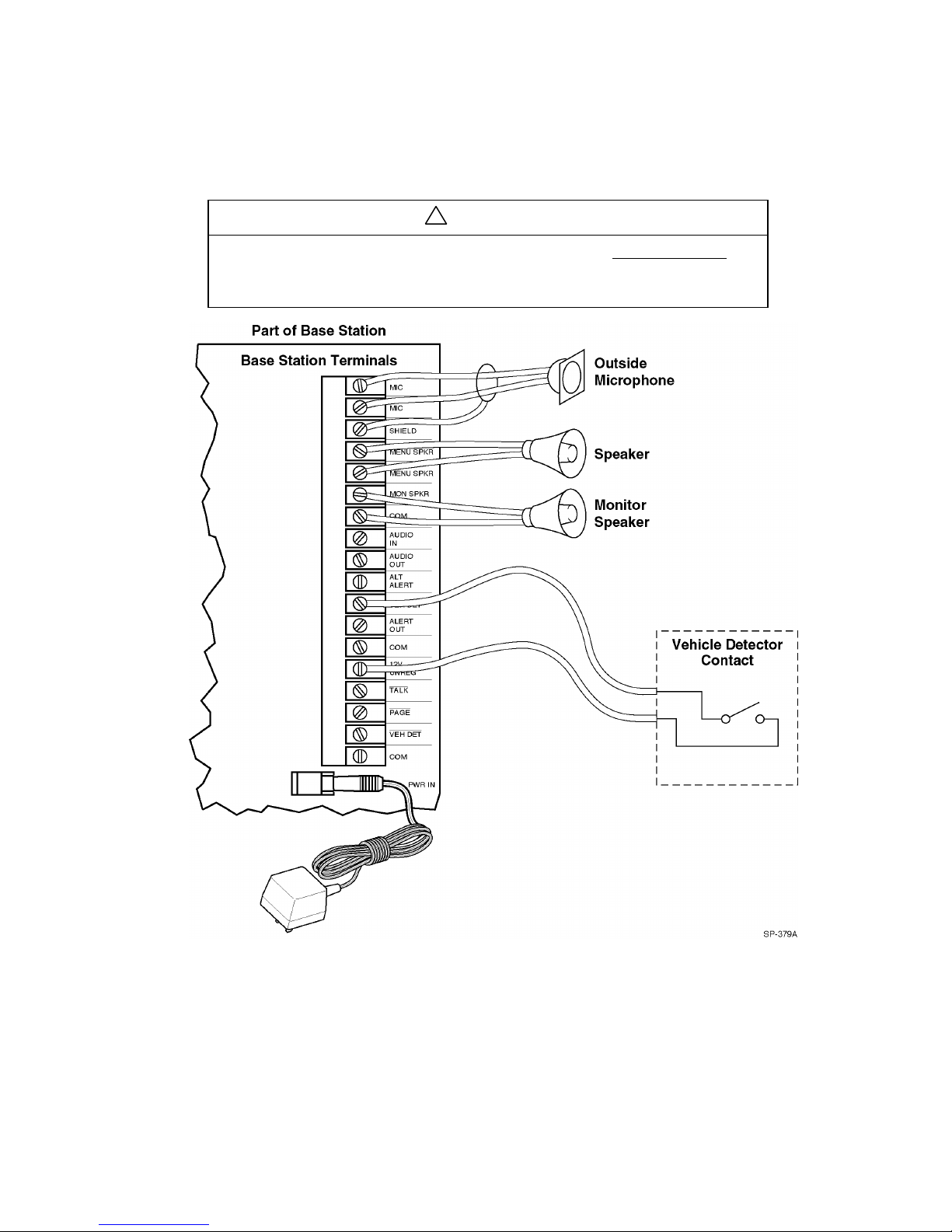
Connecting the Base Station Directly to Components
!
same jacket unless specially designed for duplex such as 3M 78–8095–0180–8.
If an interconnect module is not used, connect the components (vehicle detector, speaker/microphone and
optional monitor speaker) directly to the base station as shown in Figure 5. Use 18–20 gauge twisted pair audio
wire for all connections except the microphone. Use an 18–20 gauge shielded twisted–pair of audio wire for the
connection to the microphone.
Important
The twisted–pair of wires for the microphone connection must be shielded for
proper operation. In duplex systems, microphone and speaker cannot be in the
Figure 5. Direct Base Station–to–Component Connections
5
Page 31

6
Connecting the Base Station to Components Using the Optional Interconnect
Module
Connect the base station to the interconnect module as shown in Figure 6. Note that the connections are made to
the “TO CONTROL MODULE” terminals on the interconnect module.
Figure 6. Base Station – Interconnect Module Connections
Connect the components (vehicle detector, speaker/microphone, and optional monitor speaker) to the
interconnect module as shown in Figure 7. Note that the connections are made to the “TO OUTSIDE” terminals
on the interconnect module.
*Note
If an optional back–up (auxiliary) intercom is connected to the “TO AUXILIARY INTERCOM”
on the interconnect module, the base station must be turned off to enable operation/usage of the
back–up intercom.
Use 18–20 gauge twisted–pair audio wire for all connections except the microphone. Use an 18–20 gauge
shielded twisted–pair audio wire for the connection to the microphone.
Page 32

Brown
Yellow
Figure 7. Connecting Components to the Interconnect Module
7
Page 33

8
Connecting the Auxiliary Intercom (Optional)
*Note
The base station must be turned off to enable operation/use of the auxiliary intercom.
1. Connect the auxiliary intercom to the “TO AUXILIARY INTERCOM” terminals on the interconnect module
as shown in Figure 8 through Figure 10 (depending on the model of intercom used).
The presence alert shown is wired to operate only when the Model C960/C860 is turned off.
If a separate outside microphone is used, the auxiliary intercom must be configured for OUTSIDE MIC.
Refer to the Auxiliary Intercom Installation Instructions for information about moving any internal jumpers.
Figure 8. D–15D (M478 DA) Connections
Figure 9. D–15B and D–15C (M478 BA and CA) Connections
Page 34

!
Important
!
!
If you use a D–30 as the auxiliary intercom, a separate monitor speaker must
be provided for the Model C960/C860. (Both the Model C960/C860 and D–
30 intercoms require separate monitor speakers.)
Figure 10. D–30 Connections
Dual Lane System Installation
A dual lane system consists of two separate single lane systems that operate independently of each other. Each
single lane system has its own dedicated base station and headset(s).
To install a dual lane system:
1.
Install two single lane systems as outlined in these installation instructions, placing the base stations at least
15 feet apart from each other.
Important
If the base stations are not at least 15 feet apart, operational problems will
occur.
2. With the base stations turned off, set jumper J3 on one of the base stations so that it jumpers pins 1 and 2.
This designates the base station as a lane 1 system.
3. Set jumper J3 on the other base station so that it jumpers pins 2 and 3. This designates the base station as a
lane 2 system.
Do not set both base stations to the same lane number as this will cause
operational problems.
Important
9
Page 35

10
4. Turn on both base stations and press the RESET SWITCH on each of the base station circuit boards to “read”
the jumper setting into the microprocessor.
5. Select a channel for each of the base stations. (See page 14 for the channel selection procedure.) After you
select the channel, press the RESET SWITCH on the base station circuit boards to “read” the selection into
the microprocessor.
6. Re–program the headsets as instructed on page 15.
7.
Check the operation of each of the systems. Note that the alert tone for the Lane 1 system headsets is a
single repeating “beep” while the alert tone for the Lane 2 system headsets is a double repeating “beep.”
Cross-Lane System Installation
The Cross-Lane system provides communication for facilities that have two menu signs. It consists of two base
stations that are connected to a Cross-Lane Module. A Cross-Lane Module is a five-pole switch that allows the
two systems to be separated during hours of peak activity. Refer to the installation instructions included with the
Cross Lane Module (78–6911–4396–6). These instructions are also located in the C960 Service Manual.
A Cross-Lane Module can be useful if the manager wishes to operate each lane with a separate crew during
periods of peak activity. This is accomplished by turning the Cross-Lane switch OFF. By pressing the T1 button
on any headset, the operator can communicate with a customer at menu sign 1. By pressing the T2 button on any
headset, another operator can communicate with a customer at menu sign 2. When the Cross-Lane Module is
OFF, the operator will only hear the vehicle detector alert from the menu sign with which he or she last talked.
During periods of lower activity, the Cross-Lane Module is turned ON, allowing one headset order-taker to
operate both lanes. When the cross-lane module is turned ON, the operator will always hear vehicle detector
alerts from both menu signs. A single alert indicates a vehicle is at menu sign 1 while a double alert indicates a
vehicle is at menu sign 2.
Page 36

Installation
Notes: Both base stations must be set to the same channel number and different lane numbers.
Both base stations must be at least 12 feet apart.
Wiring the System
LOOP
DET.
SPKR
MIC
LOOP
DET.
SPKR
MIC
MIC MIC
MIC
SHIELD
MENU SPKR
MENU SPKR
MON SPKR
COM
AUDIO IN *
AUDIO OUT *
ALT ALERT
VEH DET
ALERT OUT
COM
12 VDC
* Note: Do not connect the AUDIO IN
and AUDIO OUT wires from the LANE 1
base station
CROSS LANE CONTROL
ON
AUDIO IN
AUDIO OUT
ALT ALERT
ALERT OUT
AUDIO OUT
AUDIO IN
ALERT OUT
ALT ALERT
COMMONCOMMON
OFF
MIC
SHIELD
MENU SPKR
MENU SPKR
MON SPKR
COM
AUDIO IN
AUDIO OUT
ALT
ALERT
VEH DET
ALERT OUT
COM
12 VDC
CROSS LANE CONTROL
Figure 11. Cross-Lane Wiring Diagram
Programming the Headsets for Cross-Lane Operation
Follow the steps below to program the C960 headsets for Cross-Lane operation, and disable the Talk-Lock
function. It does not matter which base station is used to program the headsets. By pressing T1, the headset will
always communicate with the lane 1 base station; by pressing T2, the headset will always communicate with the
lane 2 base station.
1.
Disable the Talk Lock function
Talk-Lock is a toggle function that must be checked first to see if it is enabled or disabled. If the Talk LED
lights when the L button is pressed, Talk-Lock is enabled.
• To disable Talk-Lock, turn the headset OFF, press and hold the L button while pressing ON for 5
seconds. You will hear an acknowledging beep.
• Recheck the Talk-Lock function by pressing the L button. The Talk LED on the base station should not
light.
11
Page 37

12
2. Program the Headsets for Cross-Lane Operation
• With the headset OFF, press and hold T1 and T2 while pressing ON for 5 seconds. You will hear an
acknowledging beep.
• Verify that the headsets are properly programmed for Cross-Lane operation:
- Press T1 and verify that the Talk LED lights on the lane 1 base station and does not light on the lane
2 base station.
- Press T2 and verify that the Talk LED lights on the lane 2 base station and does not light on the lane
1 base station.
• To remove the Cross-Lane function and return the headsets to the normal operating mode, first turn the
headset OFF, and then hold down T1 while pressing ON for 5 seconds. You will hear an
acknowledging beep.
Operation
Cross-Lane Module OFF
Vehicle detector alerts
The operator will only hear the vehicle detector alert from the menu sign with which he or she last
talked. Vehicles at menu sign 1 will be heard as a single repeating alert. Vehicles at menu sign 2 will
be heard as a double repeating alert.
Answering customers
Pressing T1 will only allow communication with the lane 1 customer. Pressing T2 will only allow
communication with the lane 2 customer.
Paging function
Pressing T1 will only allow communication with other headsets, which recently pressed T1. Pressing
T2 will only allow communication with other headsets, which recently pressed T2.
Cross-Lane Module ON
Vehicle detector alerts
The operator will always hear both vehicle detector alerts. Vehicles at menu sign 1 will be heard as a
single repeating alert. Vehicles at menu sign 2 will be heard as a double repeating alert.
Answering customers
Pressing T1 will only allow communication with the lane 1 customer. Pressing T2 will only allow
communication with the lane 2 customer.
Paging function
Pressing T1 will only allow communication with other headsets, which recently pressed T1. Pressing
T2 will only allow communication with other headsets, which recently pressed T2.
NOTES:
1. Both vehicle alert tones will be heard at all times with the Cross-Lane Module ON
The order-taker may object to hearing the vehicle alert from the other lane while taking an order; if so, we
suggest you decrease ALERT TONE LEVEL on each base station so it is audible in the headsets but not
objectionable. The tone should be low enough so that the order-taker can ignore it, yet know that someone is
waiting at the other lane.
Page 38

2. Listening and Paging in a Cross Lane system
With the AUDIO IN and AUDIO OUT wires disconnected, the T1 and T2 buttons control which menu sign
to talk or listen to. They also control which headsets to PAGE to. Disconnecting the AUDIO IN and
AUDIO OUT wires presents some issues if a cook or cashier needs to monitor both lanes:
• If the cook or cashier is using a headset to monitor lane 1, and the order-taker is taking an order from
menu lane 2, or if the order-taker needs to PAGE the cashier, he/she must first press T1 momentarily,
then press PAGE to communicate privately with the cashier on lane 1. Then the order-taker can press T2
to resume taking the order on lane 2.
• As an alternative, a monitor speaker from each base station may be installed in the kitchen. (Caution:
Monitor speakers are generally not recommended for duplex systems using C921AA base stations. The
speaker location and volume are usually too critical to avoid feedback. C921BA base stations can
usually be configured successfully to allow operation of monitor speakers.)
3.
The vehicle alerts may echo in the headsets
With the Cross-Lane module turned ON, two rapid single tones may be heard from the lane 1 base station.
To eliminate this problem, turn down the volume of the ALERT TONE LEVEL control, on one of the base
stations.
13
Page 39

14
System Configurations and Function Jumper Settings
!
Important
Whenever a jumper setting is changed, the RESET SWITCH on the base station circuit board must be pressed
to program the new jumper setting into the microprocessor. Also, each of the headsets in the system must be
reprogrammed when a jumper setting is changed (see Channel Selection on page 14 for the headset
programming procedure).
Determine the system type (standard operation – single lane, etc.) and identify the type of speaker (speaker only
or speaker and microphone) and the type of vehicle detector (air switch or loop/SODAR detector).
Refer to the base station circuit board illustration (Figure 14) and the applicable system configuration below. Set
the function jumpers as noted and per the type of speaker and vehicle detector in the system. (An illustration of
the circuit board also appears on the decal inside of the base station half–cover.)
Standard Operation – Single Lane System (One Base Station)
Function Jumper Settings
Menu Sign with Speaker only (OSM) Jumper pins 1 and 2 on jumpers J1 and J2.
or or
Menu Sign with Separate Speaker and
Microphone
Lane 1 System Jumper pins 1 and 2 of jumper J3.
Air Switch (Pulse) Detector Jumper pins 1 and 2 of jumper J4.
or or
Loop/Sodar (Presence) Detector Jumper pins 2 and 3 of jumper J4.
Standard Operation Jumper pins 2 and 3 of jumper J5.
Menu Power Selection Jumper must cover the top 2 pins of jumper J6.
Talk Monitor Level Jumper left 2 pins of jumper J9.
Jumper pins 2 and 3 on jumpers J1 and J2.
Standard Operation – Dual Lane System (Two Base Stations)
Function Jumper Settings
Menu Sign with Speaker only (OSM) Jumper pins 1 and 2 on jumpers J1 and J2.
or or
Menu Sign with Separate Speaker and
Microphone
Lane 1 System Jumper pins 1 and 2 on base station 1, jumper J3.
Lane 2 System Jumper pins 2 and 3 on base station 2, jumper J3.
Air Switch (Pulse) Detector Jumper pins 1 and 2 of jumper J4.
or or
Loop/Sodar (Presence) Detector Jumper pins 2 and 3 of jumper J4.
Standard Operation Jumper pins 2 and 3 of jumper J5.
Menu Power Selection
Talk Monitor Level Jumper left 2 pins of jumper J9.
Jumper pins 2 and 3 on jumpers J1 and J2.
Jumper must cover the top 2 pins of jumper J6.
Page 40

Duplex Operation – Single Lane System (One Base Station)
Function Jumper Settings
Menu Sign with Separate Speaker and
Jumper pins 2 and 3 on jumpers J1 and J2.
Microphone
Lane 1 System Jumper pins 1 and 2 of jumper J3.
Air Switch (Pulse) Detector Jumper pins 1 and 2 of jumper J4.
or or
Loop/Sodar (Presence) Detector Jumper pins 2 and 3 of jumper J4.
Duplex Operation Jumper pins 1 and 2 of jumper J5.
Menu Power Selection Jumper bottom 2 pins of jumper J6.
Talk Monitor Level Jumper left 2 pins of jumper J9.
or
If feedback occurs, jumper right 2 pins of
jumper J9
Duplex Operation – Dual Lane System (Two Base Stations)
Function Jumper Settings
Menu Sign with Separate Speaker and
Microphone
Lane 1 System Jumper pins 1 and 2 on base station 1, jumper J3.
Lane 2 System Jumper pins 2 and 3 on base station 2, jumper J3.
Air Switch (Pulse) Detector Jumper pins 1 and 2 of jumper J4.
or or
Loop/Sodar (Presence) Detector Jumper pins 2 and 3 of jumper J4.
Duplex Operation Jumper pins 1 and 2 of jumper J5.
Menu Power Selection Jumper bottom 2 pins of jumper J6.
Talk Monitor Level Jumper left 2 pins of jumper J9.
Jumper pins 2 and 3 on jumpers J1 and J2.
or
If feedback occurs, jumper right 2 pins of
jumper P9.
15
Page 41

16
Channel Selection
!
!
The Model C960/C860 Headset Intercom System can operate on any one of eight different channels.*
Select a channel that neither receives or causes interference and then program the headsets to that channel using
the following procedure:
1. Pull slightly outward on the lower right side of the base station half–cover and then lift and remove the cover
as shown in Figure 12.
Figure 12. Removing the Half–Cover from the Base Station
2. With the base station turned on, press and release the CHANNEL SELECT switch once. (This advances the
system to the next channel.) One of the red indicators (1–8) will light, indicating the newly selected channel.
Important
After making any changes to the base station jumper settings, you must press
the RESET SWITCH to “read” the new settings into the microprocessor.
Important
When two systems are used in a dual lane application, each base station must
be set to the same channel, and one base station must be set to Lane 1 and the
other to Lane 2.
*Note
If you are installing this as a single lane system, 8 channels on the LANE 2 setting are also
available for use.
Page 42

Channel Selection (Cont.)
Figure 13. Base Station Circuit Board
3. With the headset/belt pack turned off, plug one end of the programming cable into the headset programming
jack.
4. Plug the other end of the programming cable into the base station modular jack.
5. Turn on the headset/belt pack. (Audible tones will be heard in the headset earpiece indicating that
programming is complete.)
The headset/belt pack is now programmed to the same channel as the base station.
Repeat the channel selection procedure if interference occurs. After seven channel changes, the original channel
will again be encountered. If interference is still present and the system is a single lane system, try changing the
J3 lane designation jumper from lane 1 to lane 2. If this fails and none of the channels are interference free,
contact your 3M representative.
Setting Audio Levels
To set the audio levels, refer to the related audio level procedure below and to the illustration of the base station
circuit board (Figure 14). All the audio level adjustment controls are located on the base station circuit board.
(An illustration of the circuit board also appears on the decal mounted to the base station.)
17
Page 43

18
Duplex Systems Only
The following procedure sets system audio levels for duplex systems so that headset/belt pack volume controls
have enough “range” to allow operators to adjust headset volume to their preference.
*Note
The microphone at the menu sign must be located within four feet of the vehicle for duplex
operation.
To set the audio levels:
1. Turn the base station MENU MIC SENS control to minimum (CCW).
2. Adjust the headset volume control to maximum.
3. Press the headset Talk switch, and set the base station outbound (DAY/NIGHT) audio levels to the desired
level at the post/sign.
4. Press and hold the headset/belt pack Talk switch, and turn the base station MENU MIC SENS control up
(CW) until feedback occurs. Then turn the MENU MIC SENS level control down (CCW) until the feedback
stops.
5. Check each additional headset/belt pack (to be used in the system) at maximum volume. Verify that feedback
does not occur. If feedback occurs, adjust the MENU MIC SENS level down until the feedback stops.
6. Lower the volume control on the headset/belt pack 2 levels from maximum, and check that the inbound
audio level from the menu mic is usable. If everything is all right, the audio will be too loud.
7. Compare this inbound listen level in the headset to the page audio level from another headset.
8. Adjust the MENU MIC SENS level down (never up) to match the page audio level as required.
9. If the inbound listen level cannot be made to match the page audio level, then more acoustic isolation is
needed for the menu mic and menu speaker.
This procedure ensures that feedback will not occur even if the headset/belt pack is run at its maximum setting. It
is also a measure of how the menu sign/post components are placed in relation to one another.
Duplex and Standard Systems
*Note
For Duplex systems, the microphone at the menu sign must be located within four feet of the
vehicle for duplex operation.
For Standard (half–duplex) systems, jumper J6 must be placed in the STD position.
The following procedures apply to both duplex and standard systems.
Alert Tone Level
The alert tone level is the volume of the alert tone heard in the headset.
To set the alert tone level:
1. Turn the headset off and then on. (This sets the volume control to midrange.)
2. Have someone drive a vehicle up to the menu sign. When the vehicle is detected, you will hear the vehicle
alert tone in the headset.
Page 44

3. Adjust the HEADSET ALERT LEVEL control to provide a comfortable alert tone level in the headset
(clockwise to increase; counterclockwise to decrease).
Monitor Speaker Volume Levels
The monitor speaker volume levels are the levels for the various functions heard through the optional monitor
speaker. All adjustment controls are located on the base station circuit board. Turn the controls clockwise to
increase the volume and counterclockwise to decrease volume.
To set the monitor speaker volume levels:
1. Set the master MON VOLUME control to the midrange position.
2. With a vehicle detected at the menu sign (alert tone sounding), adjust the MON ALERT control so that the
alert signal coming through the monitor speaker is at a suitable level.
3. Press and hold the headset Talk switch and speak into the headset microphone. Adjust the MON TALK
control so that the talk audio coming through the monitor speaker is at a suitable level.
4. Press the headset Page switch and speak into the headset microphone. Adjust the MON PAGE control so
that the page audio coming through the monitor speaker is at a suitable level.
5. While you listen to audio coming from the menu sign, adjust the MON IN control so that the menu sign
audio coming through the monitor speaker is at a suitable level.
*Note
If any monitor functions are not desired by the customer, turn the related adjustment control fully
counterclockwise to silence the function.
Standard Systems Only
The following procedures apply only to standard systems.
*Note
For Standard (half–duplex) systems jumper J6 must be placed in the STD position.
Listen Level (Menu Sign Microphone Sensitivity)
The listen level is the volume of the menu sign audio heard in the headset.
To set the listen level:
1. Turn the headset/belt pack off and then on. (This sets the volume control to midrange.)
2. Have someone drive a vehicle up to the menu sign. When the vehicle is detected, you will hear the vehicle
alert tone in the headset/belt pack.
3. Press and release the headset Talk switch to cancel the alert tone and allow you to listen to the audio from the
menu sign.
4. Adjust the MENU MIC SENS level control for the desired volume (clockwise to increase volume;
counterclockwise to decrease.)
The Listen Level should now be properly adjusted. Because the headset/belt pack volume control was set at
midrange, there will now be enough range (up/down) in the headset/belt pack volume control to allow operators
to set the headset volume to a preferred level.
19
Page 45

20
Menu Sign Talk Volume Level
The menu sign talk volume level is the volume of the headset/belt pack audio heard at the menu sign.
To set the menu sign talk volume level:
1. Move the DAY/NIGHT switch on the base station to the DAY position.
2. Press and hold the headset/belt pack Talk switch and speak into the headset microphone.
3. Adjust the DAY menu sign audio level control for the desired audio level at the menu sign (clockwise to
increase; counterclockwise to decrease.)
4. Move the DAY/NIGHT switch on the base station to the NIGHT position.
5. Press and hold the headset/belt pack Talk switch and speak into the headset microphone.
6. Adjust the NIGHT menu sign audio level control so that the audio level at the menu sign is slightly lower
than the DAY audio level setting (clockwise to increase; counterclockwise to decrease.)
Page 46

Circuit Board Jumpers, Adjustment Controls, Indicators and Switches
Figure 14. Base Station Circuit Board
Jumpers
J1 and J2 Set for the type of menu sign in the system. Jumper pins 1 and 2 on both jumpers for menu
signs having a speaker only. Jumper pins 2 and 3 on both jumpers for menu signs having a
speaker and a microphone.
J3 Set to designate the number of the lane in the system. Jumper pins 1 and 2 to select lane 1.
Jumper pins 2 and 3 to select lane 2.
J4 Set for the type of vehicle detector in the system. Jumper pins 1 and 2 for an air switch
detector. Jumper pins 2 and 3 for a loop/sodar detector.
J5
J6 MENU PWR SEL – STD or DPLX
J9 TALK MON LVL
Set to designate the type of communication operation. Jumper pins 2 and 3 for standard
operation. Jumper pins 1 and 2 for duplex operation.
STD – applies power to outbound speaker amplifiers only when the TALK switch is pressed.
Note: for Standard (half–duplex) operation J6 MUST be placed in the STD position.
DPLX – applies power to outbound speaker amplifiers constantly. This will reduce the click
that is sometimes heard in duplex mode when the TALK button is pressed.
REDUCE – reduces the volume to the Monitor Speaker by 16dB while the TALK button is
pressed. This decreases the chance of feedback when a headset is operating near the Monitor
Speaker in duplex mode.
NONE – mutes the volume to the Monitor Speaker while the TALK button is pressed.
21
Page 47

22
!
After changing any jumper setting(s), be sure to press the RESET SWITCH on
the base station circuit board to “read” the change into the microprocessor.
Adjustment Controls
Important
MENU MIC SENS
HEADSET ALERT LEVEL
Controls the volume of the menu sign audio heard in the headset.
Controls the volume of the alert tone heard in the headset.
DAY Controls the volume heard at the menu sign with the Day/Night switch in
the Day position.
NIGHT Controls the volume heard at the menu sign with the Day/Night switch in
the Night position.
MON VOLUME
Master volume control for the following functions heard through the
optional monitor speaker:
MON ALERT
MON IN
MON PAGE
MON TALK
Controls the alert tone level.
Controls the audio level coming from the menu sign.
Controls the page audio level coming from the headset/belt pack
microphone.
Controls the talk audio level coming from the headset/belt pack
microphone.
*Note
If any of the monitor functions are not desired by the customer, turn the appropriate adjustment
control completely counterclockwise to silence that particular function.
Indicators
POWER
CHANNEL 1–8
VEHICLE
TALK
PAGE
Lights when power is applied to the base station.
Lit LED indicates which channel is selected for base station operation.
Lights when a vehicle is detected at the menu sign.
Lights during communication between headset/belt pack and menu sign.
Lights during paging from headset/belt pack.
Switches (etc.)
ON/OFF Switch
DAY/NIGHT VOLUME Switch
CHANNEL SELECT Switch
Programming Jack
RESET Switch
ON/OFF Switch
Connectors:
C5000 Terminal Strip
J7
J8
Controls power to the base station.
Selects volume for day or night operation.
Selects base station operating channel.
For programming headsets/belt packs to the same channel as the base
station.
For programming new channel selection or jumper setting(s) into the
microprocessor.
Switches the optional Noise Reduction Module ON or OFF.
An extra 4 terminals at the bottom of the right–hand terminal block.
Loop Detector Connector
Noise Reduction Connector (under left half–cover)
Page 48

Finishing Up
1. Secure any loose wires.
2. Replace the cover on the base station module.
3. Check the operation of the system.
4. Check the operation of the auxiliary intercom.
5. Perform operator training, including the following functions:
• Normal use and care of the system.
• Use and care of the headset.
• Battery replacement and recharging.
• Operation of the base station module switches and controls.
• Operation of optional Noise Reduction Module
• Operation of Loop Detector
Refer to the Model C960/C860 Headset Intercom System Operating Instructions.
Troubleshooting Audio Feedback
If audio feedback occurs, check the following and correct as necessary:
• Is the microphone audio cable shielded twisted pair – grounded at the inside end?
• Is the microphone audio wiring separately contained in its own cable, with no other “active” wires in the
same cable?
• Are the speaker and microphone at least 14 inches apart?
• Is the outbound audio level too high?
• Is speaker audio being reflected back to the microphone from nearby surfaces?
Technical Assistance
For technical assistance, call 1–800–328–0033 or write to 3M Communication Products at the following address:
Food Services Trade Department
3M Center, Building 551–1E–02
St. Paul, MN 55144–1000
23
Page 49

3
Food Services Trade Department
3M Center
St. Paul, MN 55144-1000
Printed on 50% recycled
waste paper, including 10%
post-consumer waste paper.
Printed in U.S.A.
3M 1999 May
78-6912-0672-2 Rev. F
Page 50

Model C960 Headset Intercom System Replacement Parts and Service
Ordering Replacement Parts
The following pages show replacement parts for the Model
C960AA Headset Intercom.
Order parts by the model number, part number, part name,
and quantity required.
Replacement parts and their prices are av a ilable by calling:
1-800-328-0033.
For replacement parts correspondence, write to:
3M Food Services Trade Department
3M Center
St. Paul, MN 55144-1000
Technical Service
For technical assistance, call:
1-800-328-0033,
or write to:
3M Food Services Trade Department
3M Center
St. Paul, MN 55144-1000
E 3M 2000 May
3-1
Page 51

Section 1 - Base Station Assembly and Interconnect Module
Model C960 Headset Intercom SystemReplacement Parts and Service
3-2
E 3M 2000 May
Page 52

Model C960 Headset Intercom System Replacement Parts and Service
Item No. Part Number Description Qty.
0 78-9236-6330-2 BASE STATION ASSEMBLY, Model C921AA (w/o Power Supply) 1........ ....... ........
1 78-8095-0500-7 CABINET, Base Station 1........ ....... ...........................................
1A 78-8095-0965--2 HINGE Assembly,(Replacement) 1....... ....... ....................................
2A 78-6911-4377-6 POWER SUPPLY, 13.5 VDC, 20 VA 1....... ....... .................................
3B 78-6911-4430-3 POWER SUPPLY, Alternate, 13.5 VDC, 1.7 A 1....... ....... ..........................
3 78-6911-3777-8 INTERCONNECT MODULE 1........ ....... .......................................
5 78-8095-0505-6 CORD, Programming 1........ ....... .............................................
E 3M 2000 May
3-3
Page 53

Section 2 - Headset Assembly
Model C960 Headset Intercom SystemReplacement Parts and Service
3-4
E 3M 2000 May
Page 54

Model C960 Headset Intercom System Replacement Parts and Service
Item No. Part Number Description Qty.
0 78-6911-4492-3 HEADSET ASSEMBLY, Model C920AC 1........ ....... ..............................
1 78-8095-0525-4 OUTER CASE (with logo) 1........ ....... .........................................
2 78-8095-0557-7 ON/OFF KEYPAD 1........ ....... ................................................
3 78-8095-0574-2 KEYPAD 1........ ....... .......................................................
4* Not Available HEADSET PWA 1....... ......... .................................................
5 78-6911-4630-8 BATTERY TERMINAL Kit (5 pairs) 2........ ....... .................................
6 78-8095-0556-9 SPRING, Battery Release Button 2........ ....... ....................................
7 78-8095-0559-3 INNER CASE ASSEMBLY 1........ ....... ........................................
8 78-8095-0551-0 BUTTON, Battery Release 1........ ....... .........................................
9 26-1014-3441-8 SCREW, Flat Head, CS, Hi-Low,4-40 x 1/4” 2........ ....... ...........................
9A 26-1002-5298-5 SCREW, Flat Head, Mach, 4-40 x .375 2....... ....... ................................
10 78-8095-0523-9 MIC BOOM ASSEMBLY (Replacement) 1....... ....... ..............................
10A 78-8095-0566-8 BASE, Mic Boom 1...... ....... ................................................
10B* Not Available BOOM, Mic 1..... ......... .....................................................
10C 78-8095-0565-0 LOCK, Mic Boom 1...... ....... ................................................
10D* Not Available SCREW, Pan Head, 4-40 x 1/4” 1..... ......... ......................................
10E 78-6911-4506-0 MIC WINDSCREEN (Package of 10) 1...... ....... .................................
11 78-8095-0524-7 SPEAKER ASSEMBLY(Replacement) 1....... ....... ...............................
11A* Not Available EAR CUP, Speaker Cover 1..... ......... ..........................................
11B* Not Available GASKET, Speaker 1..... ......... ................................................
11C* Not Available SPEAKER ASSEMBLY 1..... ......... ...........................................
11D* Not Available FOAM, Speaker 1..... ......... ..................................................
11E 78-8095-0563-5 JOINT, Ear Cup 1...... ....... ..................................................
11F* NotAvailable EAR CUP 1..... ......... .......................................................
12 78-6911-4505-2 EAR PAD(Package of 10) 1....... ....... ..........................................
13A 78-8095-0583-3 HEADBAND ASSEMBLY, Adjustable 1...... ....... ................................
13B 78-8095-0582-5 HEADBAND ASSEMBLY, Main 1...... ....... ....................................
13B-1 78-8095-0607-0 CAP, Headband WidthAdjustment 1.... ....... ...................................
14 26-1014-3439-2 SCREW, Pan Head, 6-32 x 7/16” 1....... ....... .....................................
15 78-6911-4510-2 SIDE PADASSEMBLY (Package of 10) 2....... ....... ..............................
16 78-6911-4507--8 TOPPAD ASSEMBLY (Package of 5) 1....... ....... ................................
17 78-6911-4491-5 BATTERYASSEMBLY 1....... ....... ...........................................
18 78-8095-0591-6 CAP/VISORCLIP (Package of 5) 1....... ....... ....................................
E 3M 2000 May
3-5
Page 55

Section 3 - 3-Slot Battery Charger Assembly
Model C960 Headset Intercom SystemReplacement Parts and Service
Item No. Part Number Description Qty.
1 78-8095-0580-9 3-SLOT BATTERY CHARGER ASSEMBLY, Model C923AA 1........ ....... .............
2 78-8028-9283-2 TRANSFORMERASSEMBLY, 14 VAC, 20 VA 1........ ....... ........................
3-6
E 3M 2000 May
Page 56

Model C960 Headset Intercom System Replacement Parts and Service
Section 4 - 6-Slot Battery Charger Assembly
Item No. Part Number Description Qty.
1 78-8095-0581-7 6-SLOT BATTERY CHARGER ASSEMBLY, Model C926AA 1........ ....... .............
2 78-8028-9283-2 TRANSFORMERASSEMBLY, 14 VAC, 20 VA 1........ ....... ........................
E 3M 2000 May
3-7
Page 57

Model C960 Headset Intercom SystemReplacement Parts and Service
Replacing the Headset Speaker
Tools Required:
S Phillips screwdriver
S Razor blade
S Small, flat-blade screwdriver (jeweler’s type)
S Needlenose pliers
Procedure:
1. Remove the ear pad as shown in Figure3-1.
2. Remove the headband and the battery. See
Figure 3-2.
3. Remove the outer case and and the twokeypads
and set them aside. See Figure 3-2.
!
Caution
The headset PWA isnot fastened to the innercase
assembly. Be careful not to strain the speaker
battery contact and microphone leads that are
connected to the PWA.
3-8
Figure 3-1.
E 3M 2000 May
Page 58

Model C960 Headset Intercom System Replacement Parts and Service
4. Carefully unplug the microphone and speaker
connectors from the headset PWA andset the
PWA aside. See Figure 3-3.
E 3M 2000 May
Figure 3-2.
5. Remove the connector terminals from the speaker
connector housing as shown in Figure 3-4.
3-9
Page 59

Figure 3-3.
Model C960 Headset Intercom SystemReplacement Parts and Service
6. Remove the ear cup cover from the ear cup:
a. If the cover is sealed to the cup, carefully cut
through the epoxy seal usinga sharp razor
blade.
b. Carefully insert a small, flat-blade
screwdriver between the cover and the ear cup
at the point indicated inFigure 3-5 and pry
the cover out of the ear cup.
7. Remove the ear cup joint. See Figure 3-1.
3-10
Figure 3-4.
8. Carefully withdraw the speaker leadsfrom t he
hole in the inner case.
9. Install the new headset speaker andreassemble
the headset in the reverseorder of disassembly.
n Note
Be sure to correctly align the speaker foam and
speaker gasket with the ear cup cover. Refer to
Figure 3--1.
E 3M 2000 May
Page 60

Model C960 Headset Intercom System Replacement Parts and Service
Figure 3-5.
Replacing the Mic Boom Assembly
Tools Required:
S Phillips screwdriver
S Razor blade
S Small, flat-blade screwdriver (jeweler’s type)
S Needlenose pliers
Procedure:
1. Remove the ear pad as shown in Figure3-1.
2. Remove the headband and the battery. See
Figure 3-2.
3. Remove the outer case and and the twokeypads
and set them aside. See Figure 3-2.
!
Caution
The headset PWA isnot fastened to the innercase
assembly. Be careful not to strain the speaker
battery contact and microphone leads that are
connected to the PWA.
4. Carefully unplug the microphone and speaker
connectors from the headset PWA, and set the
PWA aside. See Figure 3-3.
5. Remove the mic boom lock as shown in
Figure 3-6.
6. Remove the mic boom base from the micboom.
SeeFigure3-6.
7. Route the mic boom assembly throughthe hole in
the inner case assembly. See Figure 3-6.
8. Install the new mic boom assemblyand
reassemble the headset in thereverse order of
disassembly.
E 3M 2000 May
3-11
Page 61

Model C960 Headset Intercom SystemReplacement Parts and Service
Replacing the Battery Release Button
Spring
Tools Required:
S Phillips screwdriver
S Needlenose pliers
Procedure:
1. Remove the battery. See Figure 3-1.
2. Remove the outer case and and the twokeypads
and set them aside. See Figure 3-2.
!
Caution
The headset PWA isnot fastened to the innercase
assembly. Be careful not to strain the speaker
battery terminals and microphone leads that are
connected to the PWA.
Figure 3-6.
3. Carefully unplug the microphone and speaker
connectors from the headset PWA, andset the
PWA aside. See Figure 3-3.
4. Lift the battery releasebutton spring out of the
retainers in the housing. See Figure 3-7.
5. Install the new batteryrelease button spring,and
reassemble the headset in thereverse order of
disassembly.
3-12
E 3M 2000 May
Page 62

Model C960 Headset Intercom System Replacement Parts and Service
Figure 3-7.
E 3M 2000 May
3-13
Page 63

(Blank Page)
Model C960 Headset Intercom SystemReplacement Parts and Service
3-14
E 3M 2000 May
Page 64

Troubleshooting Guide
3Mt Headset Intercom System, Model C960
System Troubleshooting
T ouse this troubleshooting guide, locate the problem in the leftcolumn and look for the problem’spossible
causesandcorrectionsinthemiddleand rightcolumns. Possible causesare listedintheorderinwhichtheyare
most likely to happen. Check for possible causes in the given sequence to help isolate the problem.
Problem Possible Cause Solution
1. No communications. All
headsets hear static.
2. A single headset hears
static.
3. A single headset hears static.
Programming cable has no
effect.
4. A single headset is dead. No
static is heard.
1. The base station is not ON. 1. Turn the base station ON.
Make sure the power
transformeris pluggedinto the
wall outlet and into the base
station power receptacle. If
the red power light does not
come on, check for power at
the wall outlet.
2. Base station and headsets are
not programmed to same
channel.
3. The Base Station is defective. 3. Call for authorized service.
1. Headset is not programmed to
same channel as base station.
1. Defective programming cable. 1. Try to program other headsets
2. Defective headset. 2. If the other headsets program
1. The headset is not turned on. 1. Press the ON button.
2. Reprogram the headsets with
the programming cable.
1. Reprogramtheheadsetwiththe
programming cable.
with the same cable. If they
won’t program, replace the
cable.
OK, the single headset needs
repair.
5. No vehicle alert tone in
headset.
2. The battery is discharged. 2. Replace the batterywith afully
charged one.
3. The headset is defective. 3. Call for authorized service.
1. No power to the vehicle
detector.
1. Plug the vehicle detector into
power outlet or replace the
detector fuse.
Page 65

Problem SolutionPossible Cause
2. Vehicledetectoris“lockedup.” 2. Remove power to vehicle
detector for a few seconds to
reset the detector.
6. All headsets will not go into
Standby (silence) when the
vehicle leaves the menu sign.
7. Audio on all headsets cuts out
or is interrupted.
3. The base station alert tone
3. Adjust alert tone volume.
volume is set too low.
1. This is normal when a pulse
(air switch) type of vehicle
1. Press the Page switch to
silence the menu microphone.
detector is used.
2. There is a large metal object
2. Remove the object.
near the loop in the driveway
(if a loop is used).
3. The Loop detector is “locked
up.”
3. Unplug theloop detector from
the AC outlet and plug it back
in to reset the detector.
4. Defective vehicle detector. 4. Call for authorized service.
1. The cause could be radio
interference. These are
symptoms of interference:
S The operating range
between the base
station and the headsets
gets very short,
sometimes 25 feet or
less. Normally you
will hear nothing to
indicate interference.
S The Talk or Page light
flickers briefly causing
the system to leave
standby mode, and go
1. Changethechannelonthe base
station to one at least three
channels away.
S If using a single base
station, move jumper J3
to the lane 2 position.
This provides 8
additional channels from
which to choose.
S Locate and shut off
other 900 MHz devices
in the building, such as
cordless phones, video
and speaker systems,
and video monitors.
into listen mode with
no vehicle alert heard.
S The system may drop
out of Talk Lock by
itself.
S When pressingthe Channel
Select button on the Base
Station, the channel lights
move sluggishly or not at
all.
2. Loose or frayed wiring.
3. Poor location of Base Station
(behind large metal objects,
too far from work area, etc.).
2. Call for authorized service.
3. Relocate the Base Station, or
add an additional BaseStation
to extend the range of the
system.
Page 66

Problem SolutionPossible Cause
8. No Talk or listen from the
menu sign when using the
backup wired intercom. The
C960 system works OK.
9. No Talk or Page to other
headsetsfromasingleheadset,
orTalkorPage buttonsrequire
excessive pressure to operate.
10. Low Talk volume on a single
headset.
11. Louder Talk volume or
feedbackfromasingle headset.
1. The base station is turned on.
2. No power to the backup
intercom.
3. Thevolumecontrolsare settoo
1. Turn the base station OFF.
2. Turn thebackupintercomonor
plug in its power transformer.
3. Turn the volume controls up.
low on the backup intercom.
4. Defective backup intercom or
4. Call for authorized service.
wiring.
1. Dirt or grease under Talk or
1. Call for authorized service.
Page Switch.
2. Wornordefective T alkorPage
2. Call for authorized service.
switch.
3. Defective headset.
1. The holes in front of the
3. Call for authorized service.
1. Call for authorized service.
microphone are plugged with
dirt or grease.
2. Operator isnot positioning the
2. Refer to Operating Guide.
microphone correctly.
3. Defective headset. 3. Call for authorized service.
1. The holes in back of the
1. Call for authorized service.
microphone are plugged with
dirt or grease.
12. Constant programming tones
heard on a single headset.
Programming cable has no
effect.
13. The“handsfree”functiondoes
not work.
1. Defective headset. 1. Call for authorized service.
1. The Talk Lock button is not
enabled on the headset.
1. Refer to the Operating
Instructions to enable T alk
Lock.
2. The system is operating in
Standard mode.
2. Talk Lock is disabled in
Standard mode.
Page 67

Battery and Battery Charger Troubleshooting
Problem Possible Cause Solution
1. No lights come on when a
batteryis insertedinto charger.
1. Dirty contacts on battery or
charger.
1. Clean contacts on battery and
charger with an alcohol
moistened swab.
2. No power to charger. 2. Makesurepowertransformeris
plugged into charger and a
“live” outlet.
3. Defective battery. 3. Try a known good battery.
4. Defective charger. 4. Call for authorized service.
2. Short battery life. 1. Worn out batteries. 1. Replace battery.
2. The battery needs to be
2. Condition the battery.
conditioned because it was
repeatedly removed from the
headset before the low battery
alert sounded.
3. Wrong type of power
transformer used for charger.
3. Makesurepowertransformeris
marked“SecondaryVoltage14
VAC.”
3. The orange light comes on
1. Defective battery. 1. Replace the battery.
when a battery is inserted into
the charger.
4. The green light on the charger
1. Defective battery. 1. Replace the battery.
never comes on.
Food Services Trade Department
3M Center
St. Paul, MN 55144-1000
Printed on 50% recycled
waste paper, including 10%
post-consumer waste paper .
Printed in U.S.A.
ã3M 1999 May
78-6912-0680-5 Rev. C
Page 68

Model C960 Headset Intercom System Troubleshooting
Analyzing Batteries
The battery analyzer is used inconjunction with the
battery charger to test the conditionof headset
batteries. The analyzer performs fivetests:
S Discharge
S Cycle 1
S Cycle 2
S Cycle 3
S Cycle 4
DISCHARGE Test
The DISCHARGEtest discharges the battery toa
level of 1.0 volt. As the batteryis discharged, the
LCD continually displays the milliampere value in
direct proportion to the amount of energybeing
removed from the test battery. The value displayed at
the start of the test is thebattery capacity from the
previous charge. Because thistest leaves the battery
fully discharged, it is useful in testing other battery
chargers.
CYCLE 1 Test
The CYCLE 1 test is a 3-phase testthat charges,
discharges, and then recharges the battery.
During the first phase, thebattery is charged.
During the second phase, the batteryis discharged to a
level of 1.0 volt. As the batteryis discharged, the
LCD continually displays the milliampere value in
direct proportion to the amount of energybeing
removed from the test battery.
During the third phase, t he battery is fullycharged.
After the battery is charged, the LCDdisplays the
actual capacity of the batteryin milliampere hours
(mA hr). If the measured capacity is lessthan 80% of
the rated capacity of 1200mA hr, another cycle
should be initiated. Another CYCLE 1 test can be
initiated without removing the battery.
n Note
When CYCLE 1 test is selected again for the same
battery, the test skips the first phase.
CYCLE 2, CYCLE 3, and CYCLE 4 Tests
These tests are variations ofthe CYCLE 1 test,and
are used to exercise a batteryto bring backlost
capacity.
S The CYCLE 2 test performs two cyclesof charge,
discharge, and recharge.
S The CYCLE 3 test performs three cycles of
charge, discharge, and recharge.
S The CYCLE 4 testperforms four cyclesof charge,
discharge, and recharge.
Following the discharge phase of the each cycle, the
LCD displays the number ofcycles that remain.
The LCD messages are as follows forthe a typical
CYCLE 4 test:
READY
CYCLE 4
(test initiated)
(Charge, discharge, recharge)
CYCLE 3
(Charge, discharge, recharge)
CYCLE 2
(Charge, discharge, recharge)
CYCLE 1
(Charge, discharge, recharge)
READY
CYCLE 4
(test complete)
E 3M 1997 September
4-1
Page 69

Setup Procedures
1. Connect the analyzer tothe battery charger. See
Figure 4-1.
Figure 4-1.
2. Turn the battery charger ON. The analyzer will
run a short self-diagnostic test,displaying each
segment on the analyzer LCD.
When the diagnostic test is complete, the word
READY is displayed on the LCD. This indicates
the analyzer and charger are ready to perform
tests.
Initiating a Test
To initiate a test:
1. Insert the battery tobe tested intothe left-hand
slot on the battery charger. The word READY
will flash on the LCD. The analyzer remains in
this state until the testselection button is pressed.
2. Press and release the test selectionbutton to
display the first test menu. See Figure 4-2. The
next test menu is displayedeach time thetest
selection button is pressed.
n Note
Tests are initiated automatically approximately 10
seconds after they are displayed. Once a test is
initiated, the test selection button is disabled and
the test cannot be interrupted.
Model C960 Headset Intercom SystemTroubleshooting
Figure 4-2.
3. When the test is complete, theword READY will
flashontheLCD.
Interpreting Test Readings
If the measured capacity of a battery isless than 80%
of the rated capacity, t he battery should bere-tested
until the measured capacity isabove 80% OR until it
ceases to increase from one test to thenext.
If the measured capacity of a battery isless than 80%
after three or four test cycles, it should beremoved
from service and disposed of in accordance withlocal
requirements.
Error Codes
There are two error codesthat aredisplayed to
indicate that an error hasoccurred.
The code ER-1 is displayed i f the battery under test
loses contact during the test. If this code is displayed,
the test should be repeated.
The code ER-2 is displayed i f the battery under test is
out of the acceptable voltage range for charging. If
this code displays repeatedly, t he battery may havea
bad cell. It should be removed from service and
disposed of in accordance with localrequirements.
4-2
E 3M 1997 September
Page 70

Headset Intercom System
Model C960
Operating Instructions
Page 71

Page 72

Model C960 Table of Contents
i
Intended Use.....................................................................................................................................iii
FCC Information.............................................................................................................................iii
System Description..........................................................................................................................1
Introduction...................................................................................................................................1
System Configurations...................................................................................................................1
Single–Lane Standard Communication System..........................................................................1
Single–Lane Duplex Communication System ............................................................................1
Dual–Lane Standard Communication System ............................................................................1
Dual–Lane Duplex Communication System...............................................................................1
Cross–Lane Communication System.........................................................................................1
System Components.......................................................................................................................2
Base Station ............................................................................................................................2
Headset...................................................................................................................................2
Battery Charger .......................................................................................................................2
Controls and Indicator....................................................................................................................3
Base Station ..................................................................................................................................3
Headset.........................................................................................................................................4
Battery Chargers ............................................................................................................................ 6
Headset Preparation........................................................................................................................7
Introduction...................................................................................................................................7
Checking the Headset for Proper Fit................................................................................................7
Adjusting Headband Width.......................................................................................................7
Adjusting Headband Size .........................................................................................................8
Positioning the Ear Pad and Microphone ...................................................................................8
Installing the Cap Clip..............................................................................................................9
Operation..........................................................................................................................................11
System Startup...............................................................................................................................11
Turning On the Base Station ..................................................................................................... 11
Turning On the Headset............................................................................................................11
Operating Modes ...........................................................................................................................11
Standby Mode .........................................................................................................................11
Talk/Listen Mode ....................................................................................................................11
Single–Lane Standard or Duplex Communication Systems...................................................11
Dual–Lane Standard or Duplex Communication Systems.....................................................11
Cross–Lane Communication Systems..................................................................................11
3M 1999 May
Page 73

Table of Contents Model C960
ii
Talk Lock Mode (“Hands Free”)............................................................................................... 12
Page Mode..............................................................................................................................13
Page Monitor Mode.................................................................................................................13
Special Considerations ................................................................................................................... 14
Maintenance..................................................................................................................................... 15
Headset......................................................................................................................................... 15
Replacing the Battery............................................................................................................... 15
Replacing the Side Headband Pads ........................................................................................... 16
Replacing the Center Headband Pad ......................................................................................... 16
Replacing the Ear Pad .............................................................................................................. 17
Battery Charger.............................................................................................................................17
Location.................................................................................................................................. 17
Cleaning the Contacts..............................................................................................................17
Batteries........................................................................................................................................ 17
Care, Handling and Storage ...................................................................................................... 17
Battery Voltage Low Tone.......................................................................................................17
Charging Batteries...................................................................................................................17
Disposing of Batteries .............................................................................................................. 18
Making Sure Batteries are Ready for Use..................................................................................18
Important Information about C960 Rechargeable Batteries......................................................... 18
Special Instructions for System Manager ..................................................................................... 20
Programming the Headset for Cross–Lane Operation......................................................................20
Reprogramming....................................................................................................................... 20
Enabling/Disabling the Talk Lock Feature....................................................................................... 21
Changing Channels if Interference is Encountered...........................................................................21
Changing the Day/Night Switch Setting..........................................................................................23
Adjusting the Monitor Speaker Volume .......................................................................................... 24
Troubleshooting............................................................................................................................... 25
Introduction .................................................................................................................................. 25
System Troubleshooting................................................................................................................. 25
Battery and Battery Charger Troubleshooting.................................................................................. 28
Service.......................................................................................................................................... 29
3M 1999 May
Page 74

Model C960 Important Information
iii
Intended Use
The 3M Headset Intercom System, Model C960, is designed to provide 2–way
radio–frequency audio communication in quick service drive–through
restaurants and convenience stores.
Misuse of the Model C960 could result in poor performance and/or undesired
operation.
FCC Information
This device complies with part 15 of the FCC Rules. Operation is subject to the
following two conditions: (1) This device may not cause harmful interference,
and (2) this device must accept any interference received, including interference
that may cause undesired operation.
Changes or modifications not expressly approved by the party responsible for
compliance could void the user’s authority to operate the equipment.
3M 1999 May
Page 75

Important Information Model C960
iv
(Blank Page)
3M 1999 May
Page 76

Model C960 System Description
1
Introduction
Configuration
System
System
System
System
System
The 3M Model C960 Headset Intercom System is a wireless intercom system
designed for high reliability, compactness, and ease of service.
The system can be programmed to operate on any one of 16 different channels
to provide high–quality audio performance and reduce the possibility of
interference between neighboring wireless systems.
Systems
Single-Lane Standard
Communication
Single-Lane Duplex
Communication
Dual-Lane Standard
Communication
Dual-Lane Duplex
Communication
The system can be configured in one of five ways depending on the number of
menu signs (lanes) at the facility and the type of communication desired.
The single–lane standard communication system provides standard
communication (talk or listen) for facilities that have one menu sign.
The system consists of one base station and one or more headsets and battery
chargers.
The single–lane duplex communication system provides duplex communication
(simultaneous talk and listen) for facilities that have one menu sign.
The system consists of one base station and one or more headsets and battery
chargers.
The dual–lane standard communication system provides standard
communication (talk or listen) for facilities that have two menu signs.
The system consists of two independent systems - one dedicated to menu sign 1
and the other dedicated to menu sign 2. The headsets are programmed to work
with one system or the other and are labeled accordingly (1 or 2).
The dual–lane duplex communication system provides duplex communication
(simultaneous talk and listen) for facilities that have two menu signs.
The system consists of two independent systems - one dedicated to menu sign 1
and the other dedicated to menu sign 2. The headsets are programmed to work
with one system or the other and are labeled accordingly (1 or 2).
Cross-Lane
Communication
3M 2000 May
The cross–lane communication system provides duplex communication
(simultaneous talk and listen) for facilities that have two menu signs.
The system consists of two duplex systems that are connected to a cross–lane
module. The headsets are programmed for either lane 1 or lane 2.
During off–peak hours, the cross–lane module can be turned ON to link the two
systems and enable one operator to simultaneously talk and listen to customers
at menu sign 1 or menu sign 2 or with other headset operators.
During peak hours, the cross–lane module can be turned OFF to separate the
systems and enable menu sign 1 operators to talk to customers at menu sign 1,
and menu sign 2 operators to talk to customers at menu sign 2.
Page 77

System Description Model C960
2
Components
Base Station
Headset
Battery Charger
Systems
The number of system components and the procedures necessary to operate
them vary depending on the system configuration. However, three components
are common to all system configurations.
The base station is the interface between the customer at the menu sign and the
headset worn by the operator. See Figure 1.
Figure 1. Base Station
The headset is a wireless, battery–powered, two–way radio used by the operator
to communicate with menu sign customers and with other store personnel who
are wearing headsets.
Headsets feature a light–weight design to provide for comfort. The headset pads
can be easily removed and reinstalled, so operators can have their own set of
pads for improved hygienic conditions. See Figure 2.
The battery charger charges headset batteries in approximately 1.5 to 2 hours.
The charger is available in 3–slot and 6–slot versions. See Figure 3.
Figure 2. Headset
Figure 3. 3–Slot and 6–Slot Battery Chargers
3M 2000 May
Page 78

Model C960 Controls and Indicators
3
Base Station
1 ON/OFF Switch
Indicator
Switch
Button
7 Page Indicator
8 Talk Indicator
9 Vehicle Indicator
Access
The base station controls and indicators are shown below.
Figure 4. Base Station Controls and Indicators
The ON/OFF switch controls power to the base station.
2 POWER
3 VOLUME
DAY/NIGHT
6 NRM On/Off
10 Monitor Volume
This indicator lights when the ON/OFF switch is in the ON position.
ü Note
If for some reason the C960 headset system does not operate and the system
includes an optional wired backup system, turn off the C960 Base Station to
enable the backup system.
With the switch in the DAY position, the volume of the menu sign speaker is
increased for daytime operation. With the switch in the NIGHT position, the
volume of the menu sign speaker is decreased for nighttime operation. (Sound
travels further and more efficiently at night.)
These indicators light to show which of the 8 channels is selected.
This indicator blinks when the Noise Reduction Module is switched on.
This button turns the optional Noise Reduction Module on or off.
This indicator lights when headset Page communications occur.
This indicator lights when headset–to–menu sign “Talk” communications occur.
This indicator lights when a vehicle is detected at the menu sign.
This access hole allows for adjusting the volume of the optional monitor
speaker.
3M 2000 May
Page 79

Controls and Indicators Model C960
4
1 ON Switch
Headset
2 OFF Switch
Control
Control
Switch
The headset controls are shown below.
3 Volume UP
4 Volume DOWN
5 T1 (Talk Lane 1)
Figure 5. Headset Controls
Press the ON switch to turn on the headset.
Press the OFF switch to turn off the headset.
Press the volume up control to increase the volume in the headset earpiece.
Press the volume down control to decrease the volume.
When either volume control is pressed, the headset emits a short tone to indicate
the new volume level. There are 15 different volume levels from minimum to
maximum.
If the headset volume is at its maximum level, a low, continuous tone sounds
when the volume up control is pressed. A low, continuous tone also occurs
when the volume reaches minimum level and the volume down control is
pressed.
When the headset is turned on, headset volume automatically returns to the
previously–set level. Note that even when set to its lowest level, headset
volume is not turned completely off.
Press and hold the T1 (Talk Lane 1) switch to talk to the customer at the menu
sign in lane 1. Release the switch to listen.
3M 2000 May
Page 80

Model C960 Controls and Indicators
5
Switch
7 Page Switch
9 Battery Release
10 Battery
Programming Jack
12 Microphone/Filter
13 Earphone/Earpad
Adjustment Slide
Adjustment Tab
6 T2 (Talk Lane 2)
8 Talk Lock Switch
11 Headset
For dual–lane systems, press and hold the T2 (Talk Lane 2) switch to talk to the
customer at the menu sign in lane 2. Release the switch to listen.
For single–lane systems, T2 can also be used to talk to lane 1.
Press and hold the Page switch to talk to internal personnel without being heard
by the customer at the menu sign. Release the switch to listen. (With the switch
released, you can hear both menu sign customers and internal paging.)
For duplex systems, press the talk lock switch once to talk and listen to the
customer. This enables hands–free operation.
Push the battery release up and hold it there while sliding the battery out of the
headset housing.
This rechargeable battery provides power to the headset.
This jack accepts the programming cable from the base station to allow the
headset to be programmed to the same channel as the base station.
The microphone sends the headset operator’s voice to the menu sign or other
headset operators. The filter is a protective cover for the microphone.
The earphone is a speaker that broadcasts the voice from the customer at the
menu sign or from other headset operators. The replaceable earpad covers the
earphone and cushions the operator’s ear to provide comfort.
15 Headband
16 Headband Width
The headband pads cushion the operator’s head to provide comfort.
The headband adjustment slide is used to increase or decrease the size of the
headband.
The headband width adjustment tab is used to increase or decrease the headband
pad pressure.
3M 2000 May
Page 81

Controls and Indicators Model C960
6
Battery Chargers
1 Charging Slots
Charging Slot
Indicators
Button
6 Power Supply Jack
Power Supply
The 3–slot and 6–slot battery charger controls are shown below.
(Rear View)
The charging slots hold batteries during the recharging cycle.
(Rear View)
2 Conditioning
and/or
3 Charging Status
4 Conditioning
5 Conditioning
7
This dual–function slot holds a battery during conditioning and recharging
cycles. This slot functions as a conditioning slot when the conditioning button is
pressed.
The charging status indicators light RED, GREEN, or ORANGE to indicate
charging status:
RED indicates the battery is being charged.
GREEN to indicate the battery is fully charged.
ORANGE to indicate the battery is defective.
Press the conditioning button to condition a battery that is inserted in the
conditioning/charging slot.
The conditioning status indicator lights YELLOW to indicate the battery in the
conditioning slot is being conditioned.
This jack accepts the plug from the power supply cord.
The power supply provides power to the battery charger.
3M 2000 May
Page 82

Model C960 Headset Preparation
7
Introduction
Fit
Width
To prepare the headset for use, you will need to check the headset for proper fit
and install the cap clip (if desired).
Checking the
Headset for Proper
Adjusting Headband
To ensure effective operation and comfort:
• Adjust the headband width.
• Adjust the headband size.
• Position the ear pad and microphone.
Adjust the headband width until the headband pads hold the headset firmly in
place without causing discomfort. The headset can be worn with the ear pad
against either ear. The three width settings are shown in Figure 6.
If the headset is too tight:
1. Fold the headband in toward the ear pad.
2. Push the width adjustment tab away from the center headband pad.
3. Fold the headband out against the adjustment tab.
If the headset is too loose:
1. Fold the headband in toward the ear pad.
2. Push the width adjustment tab toward the center headband pad.
3. Fold the headband out against the adjustment tab.
3M 2000 May
Small
Medium
Large
Figure 6. Headband Width
Page 83

Headset Preparation Model C960
8
Size
Pad and Microphone
Adjusting Headband
Adjust the size of the 2–piece headband until the ear pad rests against one ear
and the headband pads rest just above each ear.
• Slide the headband apart to make it larger.
• Push the headband together to make it smaller.
Positioning the Ear
Figure 7. Headband Size
Rotate the microphone boom up or down so that its tip is in line with the corner
of your mouth. Do not bend the rubber microphone boom. See Figure 8.
Figure 8.
3M 2000 May
Page 84

Model C960 Headset Preparation
9
Installing the Cap Clip
To install the cap clip:
1. Remove the side headband pad (from above the ear pad). Insert a dime in
the slot on the headband pad housing and twist the dime to release the tab.
See Figure 9.
Headband Pad
Tab
Slot
Coin
Figure 9.
2. Extend the headband to maximum size.
3. Using a ball point pen, release the headband latch and slide the 2–piece
headband apart. See Figure 10.
Headband
Latch
3M 2000 May
Figure 10.
Page 85

Headset Preparation Model C960
10
4. Slide the cap clip onto the cap band just above the ear.
Cap
Band
Cap
Clip
Figure 11.
5. Slide the cap clip over the inside half of the adjustable headband until it
snaps into position over the headband pad mount. See Figure 12.
Figure 12.
3M 2000 May
Page 86

Model C960 Operation
11
System Startup
Station
Headset
Operating Modes
Standby Mode
Talk/Listen Mode
System startup includes turning on the base station and each headset that will be
used.
Turning On the Base
Turning On the
To turn on the base station:
1. Slide the power ON/OFF switch to the ON position. Check to see that the
POWER indicator lights.
2. Slide the VOLUME switch to the desired position (DAY or NIGHT).
To turn on the headset, press the ON switch located on the transceiver housing.
A single tone will sound in the earphone to indicate the headset has been turned
on.
The system has several operating modes. The number of available operating
modes depends on the system configuration (single–lane vs dual–lane, standard
communication vs duplex communication, etc.).
In the standby mode, the headset is on and waiting to receive communication
from the menu sign or other headset operators. This mode is available with all
system configurations.
Use the talk/listen mode to talk to the customer at the menu sign. This mode is
available with all system configurations.
Single–Lane Standard or Duplex Communication Systems
1. A single beep alert tone sounds in the headset at 2–second intervals when
the system detects a customer (vehicle) at the menu sign.
2. When you hear the alert tone, press and hold T1 or T2 to talk to the
customer at the menu sign. Release T1 or T2 to listen.
Dual–Lane Standard or Duplex Communication Systems
In dual–lane systems, some headsets are programmed to communicate with
Lane 1 and others are programmed to communicate with Lane 2. The headsets
are labeled accordingly.
1. An alert tone sounds in the headset when the system detects a customer
(vehicle) at the menu sign:
• The alert tone for Lane 1 is a single beep that repeats at 2–second
intervals.
• The alert tone for Lane 2 is a double beep that repeats at 2–second
intervals.
2. When you hear the single beep alert tone, press and hold T1 and talk to the
customer at menu sign 1. Release T1 to listen.
When you hear the double beep alert tone, press and hold T2 to talk to the
customer at the menu sign 2. Release T2 to listen.
Cross–Lane Communication Systems
Communication During Peak Hours
During peak hours, the cross–lane module is turned off and the system functions
like a dual–lane duplex system. Some headsets are programmed to
communicate with Lane 1 and others are programmed to communicate with
Lane 2. The headsets are labeled accordingly.
3M 2000 May
Page 87

Operation Model C960
12
Communication During Off–Peak Hours
During off–peak hours, the cross–lane module is turned on to enable a single
operator to communicate with customers in either lane (1 or 2).
1. An alert tone sounds in the headset when the system detects a customer
(vehicle) at the menu sign:
• The alert tone for Lane 1 is a single beep that repeats at 2–second
intervals.
• The alert tone for Lane 2 is a double beep that repeats at 2–second
intervals.
2. When you hear the single beep alert tone, press and hold T1 and talk to the
customer at menu sign 1. Release T1 to listen.
When you hear the double beep alert tone, press and hold T2 to talk to the
customer at the menu sign 2. Release T2 to listen.
Talk Lock Mode
Use this mode to operate “hands free.“ The talk lock mode is only available
with duplex system configurations.
In this mode, the headset automatically switches from standby to talk/listen
when a customer is detected at the menu sign. The headset automatically
switches back to standby when the customer leaves the menu sign.
ü Notes
“Hands free” operation (talk lock mode) prevents all other headset operators
from communicating.
“Hands Free” operation will not work in cross lane mode.
To use the talk lock mode, press the talk lock switch on the transceiver housing.
To return to normal headset operation, press T1 or P.
3M 2000 May
Page 88

Model C960 Operation
13
Page Mode
Page Monitor Mode
Use this mode to talk to other operators who are wearing headsets without being
heard by the customer at the menu sign. This mode is available with all system
configurations.
To page another operator, press and hold the page switch. Release the page
switch to listen.
ü Note
If you are not a menu sign operator, do not use the page mode while the menu
sign operator is communicating. Doing so may interrupt or prevent
communication between the menu sign operator and the customer.
Use this mode to listen for pages from other operators (without hearing the
communication to and from the menu sign). This feature is convenient for
managers and supervisors who only want to hear page communication. This
mode is available with all system configurations.
To use the page monitor mode:
1. Turn the headset OFF. See Figure 13.
ON
Press OFF Switch
T2
L
P
T1
Figure 13. OFF Switch
2. While pressing and holding the page switch, turn the headset ON. This
locks the headset in the page monitor mode. See Figure 14.
3M 2000 May
Page 89

Operation Model C960
14
...then press ON
Press and hold page switch...
LT2T1
Considerations
B
OFF
A
Figure 14. Page Switch and OFF Switch
Special
To respond to a page, press P (page switch).
To return to normal headset operation:
1. Turn the headset OFF.
2. Turn the headset ON.
When using the talk/listen mode or the page mode, keep the following things in
mind:
• Communication between the menu sign operator and the customer may be
heard by several people.
• Only one headset operator can talk at a time.
• In the talk/listen mode, communication from the headset is heard by menu
sign customers and other operators who are wearing headsets.
• In the talk/listen and page modes, communication from the menu sign is
heard by other operators who are wearing headsets.
3M 2000 May
Page 90

Model C960 Maintenance
15
Headset
Replacing the Battery
When the battery voltage is too low, the headset sounds a short, low–volume
tone at seven–second intervals to alert the operator to install a fully charged
battery. The “battery voltage low tone” continues for two minutes after which
the headset turns off automatically to prevent damage to the batteries.
ü Note
When installing a battery, make sure it is fully charged. It is important to
remember that an unused C960 battery loses five percent of its charge per
week. If a batteries has not been used for several weeks, make sure to charge
prior to use.
To replace the battery:
1. Push and hold the battery release. See Figure 15.
2. Push the discharged battery out of the transceiver housing.
3. Insert a fully charged battery in the housing with the notch facing the
battery release. Make sure the battery is fully inserted (battery release
clicks). See Figure 15.
Battery
Release
Battery
Battery
Release
Notch
Figure 15.
3M 2000 May
Page 91

Maintenance Model C960
16
Headband Pads
Headband Pad
Replacing the Side
To replace the side headband pads:
1. Insert the edge of a dime into the slot on the headband pad housing. See
Figure 16.
2. Twist the dime to release the tab.
Headband Pad
Tab
Slot
Coin
Replacing the Center
Figure 16.
To replace the center headband pad:
1. Insert the edge of a dime between the main headband and the top headband
pad and pry up to remove the pad. See Figure 17.
2. Snap the new pad into place.
Main
Headband
Coin
Pad
Figure 17.
3M 2000 May
Page 92

Model C960 Maintenance
17
Replacing the Ear Pad
Battery Charger
Cleaning the Contacts
Batteries
Storage
Tone
Charging Batteries
To replace the ear pad, remove the worn/damaged ear pad from the ear cup and
replace it with a new pad.
The battery charger should be placed on a flat surface such as a desktop or table
in a clean, dry environment.
If the indicators fail to light during charger operation, clean the contacts using an
alcohol–moistened cotton swab.
Care, Handling and
Battery Voltage Low
Avoid dropping batteries.
Do not carry batteries in your pockets or leave them in hot, damp or dirty places.
Clean the battery contacts periodically using an alcohol–moistened swab.
Be careful not to short the battery contacts together.
Do not set the batteries contact–side down on a bare metal countertop-especially
if it is damp.
When the battery voltage becomes too low, a short, low–volume tone sounds in
the headset at seven–second intervals to alert the operator to replace with a fully
charged battery.
The “battery voltage low tone” continues for two minutes after which the
headset turns off automatically to prevent damage to the batteries.
To charge a battery, insert the battery in one of the charging slots as shown in
Figure 18.
• The indicator lights RED to indicate the battery is charging.
• The indicator lights GREEN to indicate the battery is fully charged.
• The indicator lights ORANGE to indicate the battery is defective.
ü Note
Discharged batteries require 1–1/2 to 2 hours to charge.
3M 2000 May
Charging
Status
Indicator
Figure 18.
Page 93

Maintenance Model C960
18
Disposing of Batteries
are Ready for Use
Batteries
To condition a battery:
1. Insert the battery in the charging/conditioning slot as shown in Figure 19.
2. Press the conditioning button within 2 seconds after inserting the battery.
The indicator lights YELLOW to indicate the battery is being conditioned.
Conditioning
Status Indicator
Conditioning
Button
Figure 19.
Making Sure Batteries
Important
Information about
C960 Rechargeable
To help protect the environment, C960 rechargeable batteries which have
reached the end of their useful life should be disposed of in accordance with
local requirements.
Follow these tips to make sure batteries are always ready for use:
• Have an extra battery for each headset. This helps ensure that a fully
charged battery is always available.
• Recharge a low battery as soon as it is removed from the headset. When a
battery is low, repeat tones are heard in the headset.
• Keep the battery contacts clean: both those on the battery and those in the
headset battery holder. To clean the contacts, use an alcohol–moistened
cotton swab.
• Remember that a battery recharge takes approximately 1–1/2 to 2 hours.
• Avoid removing and reinserting batteries while they are charging (charging
status indicator is RED).
• Remember that batteries discharge fastest during Talk and Page operation.
Avoid unnecessary communications.
Keep the following information in mind as you operate the system and as you
establish operating procedures:
• Each 3M battery contains an internal protective device to prevent unsafe
discharge rates. But, as with any battery, avoid shorting across the battery
contacts with metal items. Never carry a battery in a pocket or place it in a
drawer where it can accidentally be shorted by keys, coins etc.
• Have adequate charging capacity for the number of headsets in your system.
One 3–slot battery charger will handle up to three headsets. Use of more
than three headsets requires a 6–slot battery charger.
3M 2000 May
Page 94

Model C960 Maintenance
19
• Batteries perform best at moderate temperatures. Extremes of heat and cold
reduce their performance.
• An unused C960 battery loses five percent of its charge per week. Batteries
that have not been used for several weeks should be recharged before use.
3M 2000 May
Page 95

Special Instructions for System Manager Model C960
20
Lane Operation
Reprogramming
Programming the
Headset for Cross-
The headsets are factory programmed for single–lane operation to enable the
operator to press either T1 or T2 to communicate with lane 1.
For cross–lane systems, the headsets must also be programmed to enable
communication with either lane 1 or lane 2. With the cross–lane module turned
ON, the lane 1 or lane 2 operators can press T1 to talk to to lane 1 customers or
T2 to talk to lane 2 customers.
To program the headset for cross–lane operation:
• While pressing and holding both the T1 and T2 switches on the headset, turn
the headset ON. Hold all three switches for at least 5 seconds. See Figure
20.
• Audible tones will be heard in the headset earpiece, indicating that the
headset is programmed for cross–lane operation.
Hold all 3 switches for 5 seconds
...then press ON switch
Press and hold both T1 and T2...
Figure 20.
To remove this function and lock T1 and T2 back together, first turn the headset
OFF, then hold down either T1 or T2 while pressing ON for 5 seconds. You
will hear an acknowledging beep. (Holding down T1 configures the headset to
be a lane 1 headset; holding down T2 configures it for lane 2.
3M 2000 May
Page 96

Model C960 Special Instructions for System Manager
21
Feature
Encountered
Enabling/Disabling
the Talk Lock
The talk lock feature provides hands free operation in duplex communication
systems. With the talk lock feature enabled, the headset automatically switches
from standby to talk/listen when a customer is detected at the menu sign. The
headset automatically switches back to standby when the customer leaves the
menu sign.
To enable or disable the talk lock feature:
1. Turn the headset OFF.
2. Press and hold the L button while pressing and holding the ON button until
audible tones are heard. This indicates that the feature has been enabled or
disabled.
3. Check headset operation to determine if the talk lock feature has been
disabled or enabled. With the talk lock feature enabled:
• The headset automatically switches from standby to talk/listen when a
customer is detected at the menu sign.
• The headset automatically switches back to standby when the customer
leaves the menu sign.
ü Note
The headsets are shipped with the talk lock feature enabled.
Changing Channels
if Interference is
Symptoms of Interference:
• The operating range between the base station and the headsets gets very
short, sometimes 25 feet or less.
• Normally, you will hear nothing to indicate interference. Occasionally, you
might hear a whistle or a chirp in the background, but seldom, if ever, will
you hear talking.
• The Talk or Page LED flickers briefly causing one of the following:
a. The system may leave the STANDBY mode, and go into the LISTEN
mode with no vehicle alert heard.
b. The system may drop out of TALK LOCK by itself.
Solutions:
• Change the base station to another channel, at least three channels away. A
better solution is to change jumper J3 to Lane 2 if possible.
• Locate and shut off other 900 MHz devices in the building, such as cordless
phones, video systems, and speaker systems.
• In cases where a cellular phone tower is nearby, certain combinations of cell
frequencies may cause interference. In some cases, changing channels may
have no effect. Please call you local 3M Dealer, or 3M F.S.T.
Communications Products Technical Service (800–328-0033) in these cases.
3M 2000 May
Page 97

Special Instructions for System Manager Model C960
22
The C960 system is capable of operating on any one of eight different channels.
You can correct these types of interference by changing the base station
operating channel. To do this:
1. Pull outward on the right side of the base station half–cover and then lift and
remove the cover. See Figure 21.
Half Cover
Figure 21.
2. With the base station turned on, press and release the Channel Select switch
once. (This advances the system to the next channel.) One of the red
indicators (1–8) will light, indicating the newly selected channel.
3.
Press the RESET switch to “read” the new channel selection into the
Figure 22.
microprocessor.
3M 2000 May
Page 98

Model C960 Special Instructions for System Manager
23
Access
Setting
ü Note
When two systems are used in a cross–lane application, both base stations must
be set to the same channel.
4. With the headset turned OFF, plug one end of the programming cable into
the headset programming jack. See Figure 22.
5. Plug the other end of the programming cable into the base station
programming jack. See Figure 22.
6. Turn the headset ON. Audible tones will be heard in the headset earpiece,
indicating that programming is complete.
7. Repeat Steps 1 through 6 to program the rest of the headsets.
The headset is now programmed to the same channel as the base station. If
interference continues to occur, repeat the channel programming procedure.
After seven channel changes, the original channel will again be encountered. If
none of the 8 channels are interference–free, try 8 additional channels on lane 2
by following the steps below: Note: These steps may be used for single–lane
systems only.
Changing the
Day/Night Switch
1. On the base station, move jumper J3 to LANE 2.
2. Press the RESET button, or turn the base station OFF, then back ON.
3. Program all headsets with the programming cable by repeating the steps
listed previously in “Changing Channels if Interference is Encountered.”
Outdoors, sound travels best at night when air temperatures are cooler and
background noise is reduced. To allow you to reduce the volume of the menu
sign speaker to a lower, pre–set nighttime level, the base station has a VOLUME
DAY/NIGHT switch. See Figure 23.
3M 2000 May
Day/Night
Switch
Figure 23.
Normally, the VOLUME DAY/NIGHT switch is always left in the DAY
position.
Monitor
Volume
Page 99

Special Instructions for System Manager Model C960
24
Volume
However, if local ordinances require quieter nighttime operation of the menu
sign, move the VOLUME DAY/NIGHT switch to the NIGHT position.
Adjusting the
Monitor Speaker
If the system has an optional monitor speaker, adjust its volume using the
following procedure:
1. With the base station turned ON, insert a small straight–blade screwdriver
into the MONITOR VOLUME access hole. See Figure 23.
2. Turn the volume control clockwise to increase the volume or
counterclockwise to decrease it.
3M 2000 May
Page 100

Model C960 Troubleshooting
25
1. Reprogram the headset with the
2. Replace the battery with a fully
2. Vehicle detector is “locked up.”
Introduction
To use the following troubleshooting guide, locate the problem in the left
column and look for the problem’s possible causes and corrections in the middle
and right columns. Possible causes are listed in the order in which they are most
likely to happen. Check for possible causes in the given sequence to help isolate
the problem.
System Troubleshooting
Problem Possible Cause Solution
1. No communications. All
headsets hear static.
1. The base station is not ON.
1. Turn the base station ON.
Make sure the power
transformer is plugged into the
wall outlet and into the base
station power receptacle. If
the red power light does not
come on, check for power at
the wall outlet.
2. A single headset hears
static.
3. A single headset hears static.
Programming cable has no
effect.
4. A single headset is dead. No
static is heard.
5. No vehicle alert tone in
headset.
2. Base station and headsets are
not programmed to same
channel.
3. The Base Station is defective. 3. Call for authorized service.
1. Headset is not programmed to
same channel as base station.
1. Defective programming cable. 1. Try to program other headsets
2. Defective headset. 2. If the other headsets program
1. The headset is not turned on. 1. Press the ON button.
2. The battery is discharged.
3. The headset is defective. 3. Call for authorized service.
1. No power to the vehicle
detector.
2. Reprogram the headsets with
the programming cable.
programming cable.
with the same cable. If they
won’t program, replace the
cable.
OK, the single headset needs
repair.
charged one.
1. Plug the vehicle detector into
power outlet or replace the
detector fuse.
3M 2000 May
3. The base station alert tone
volume is set too low.
2. Remove power to vehicle
detector for a few seconds to
reset the detector.
3. Adjust alert tone volume.
 Loading...