

Page 1
Belt Pack Intercom System
Model C860
Operating Instructions
Page 2

Page 3

Model C860 Table of Contents
Intended Use........................................................................................................................................... iii
FCC Information................................................................................................................................... iii
System Description ................................................................................................................................ 1
Introduction..................................................................................................................................................... 1
System Configurations.................................................................................................................................... 1
Single-Lane Standard Communication System........................................................................................ 1
Single-Lane Duplex Communication System........................................................................................... 1
Dual-Lane Standard Communication System........................................................................................... 1
Dual-Lane Duplex Communication System............................................................................................. 1
Cross-Lane Communication System......................................................................................................... 1
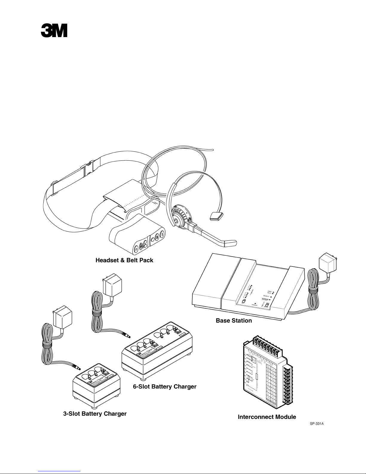
System Components........................................................................................................................................ 2
Base Station.............................................................................................................................................. 2
Headset and Belt Pack.............................................................................................................................. 2
Battery Charger......................................................................................................................................... 2
Controls and Indicators ........................................................................................................................ 3
Base Station..................................................................................................................................................... 3
Headset and Belt Pack..................................................................................................................................... 4
Battery Chargers.............................................................................................................................................. 6
Headset/Belt Pack Preparation ............................................................................................................ 7
Introduction..................................................................................................................................................... 7
Checking the Headset for Proper Fit............................................................................................................... 7
Positioning the Microphone...................................................................................................................... 7
Connecting the Headset to the Belt Pack.................................................................................................. 8
Installing the Belt Pack............................................................................................................................. 8
Wearing the Belt Pack.............................................................................................................................. 9
Operation................................................................................................................................................ 10
System Startup................................................................................................................................................. 10
Turning On the Base Station..................................................................................................................... 10
Turning On the Belt Pack......................................................................................................................... 10
Operating Modes............................................................................................................................................. 10
Standby Mode........................................................................................................................................... 10
Talk/Listen Mode...................................................................................................................................... 10
Talk Lock Mode (“Hands Free”).............................................................................................................. 11
Page Mode................................................................................................................................................ 12
Page Monitor Mode.................................................................................................................................. 12
3M 2003 January i
Page 4

Table of Contents Model C860
Special Considerations.................................................................................................................................... 13
Maintenance........................................................................................................................................... 14
Belt Pack......................................................................................................................................................... 14
Replacing the Battery............................................................................................................................... 14
Replacing the Headset Pad....................................................................................................................... 14
Battery Charger............................................................................................................................................... 15
Location.................................................................................................................................................... 15
Cleaning the Contacts............................................................................................................................... 15
Batteries.......................................................................................................................................................... 15
Care, Handling and Storage...................................................................................................................... 15
Battery Voltage Low Tone....................................................................................................................... 15
Charging Batteries.................................................................................................................................... 15
Disposing of Batteries.............................................................................................................................. 16
Making Sure Batteries are Ready for Use................................................................................................ 16
Important Information about C860 Rechargeable Batteries..................................................................... 16
Special Instructions for System Manager ........................................................................................... 18
Programming the Belt Pack for Cross-Lane Operation.................................................................................. 18
Reprogramming........................................................................................................................................ 18
Changing Channels if Interference is Heard................................................................................................... 19
Changing the Day/Night Switch Setting......................................................................................................... 20
Adjusting the Monitor Speaker Volume......................................................................................................... 21
Troubleshooting..................................................................................................................................... 22
Introduction..................................................................................................................................................... 22
System Troubleshooting................................................................................................................................. 22
Battery and Battery Charger Troubleshooting................................................................................................ 24
Service ............................................................................................................................................................ 25
ii 3M 2003 January
Page 5

Model C860 Important Information
Intended Use
The 3M Belt Pack Intercom System, Model C860, is designed to provide 2-way
radio-frequency audio communication in quick service drive-through restaurants
and convenience stores.
Misuse of the Model C860 could result in poor performance and/or undesired
operation.
FCC Information
This device complies with part 15 of the FCC Rules. Operation is subject to the
following two conditions: (1) This device may not cause harmful interference,
and (2) this device must accept any interference received, including interference
that may cause undesired operation.
Changes or modifications not expressly approved by the party responsible for
compliance could void the user’s authority to operate the equipment.
3M 2003 January iii
Page 6

Important Informat ion Model C860
(Blank Page)
iv 3M 2003 January
Page 7

Model C860 System Description
Introduction
System
Configurations
Single-Lane Standard
Communication
System
Single-Lane Duplex
Communication
System
Dual-Lane Standard
Communication
System
The 3M Model C860 Belt Pack Intercom System is a wireless intercom system
designed for high reliability, compactness, and ease of service.
The system can be programmed to operate on any one of eight different radio
channels to provide high-quality audio performance and reduce the possibility of
interference between neighboring wireless systems.
The system can be configured in one of five ways depending on the number of
menu signs (lanes) at the facility and the type of communication desired.
The single-lane stan dard c ommunica tion system provides standard
communication (talk or listen) for facilities that have one menu sign.
The system consists of one base station and one or more belt packs and battery
chargers.
The single-lane duplex communication system provides duplex communication
(simultaneous talk and listen) for facilities that have one menu sign.
The system consists of one base station and one or more belt packs and battery
chargers.
The dual-lane stan dard co mmunicat ion system provides standard
communication (talk or listen) for facilities that have two menu signs.
The system consists of two independent systems - one dedicated to menu sign 1
and the other dedicated to menu sign 2. The belt packs are programmed to work
with one system or the other and are labeled accordingly (1 or 2).
Dual-Lane Duplex
Communication
System
Cross-Lane
Communication
System
The dual-lane duplex communication system provides duplex communication
(simultaneous talk and listen) for facilities that have two menu signs.
The system consists of two independent systems - one dedicated to menu sign 1
and the other dedicated to menu sign 2. The belt packs are programmed to work
with one system or the other and are labeled accordingly (1 or 2).
The cross-lane communication system provides duplex communication
(simultaneous talk and listen) for facilities that have two menu signs.
The system consists of two duplex systems that are connected to a cross-lane
module. The belt packs are programmed for either lane 1 or lane 2.
During off-peak hours, the cross-lane module can be turned ON to link the two
systems and enable one operator to simultaneously talk and listen to customers
at menu sign 1 or menu sign 2 or with other headset operators.
During peak hours, the cross-lane module can be turned OFF to separate the
systems and enable menu sign 1 operators to talk to customers at menu sign 1,
and menu sign 2 operators to talk to customers at menu sign 2.
3M 2003 January 1
Page 8
System Description Model C860
System
Components
Base Station
Headset and Belt Pack
The number of system components and the procedures necessary to operate
them vary depending on the system configuration. However, three components
are common to all system configurations.
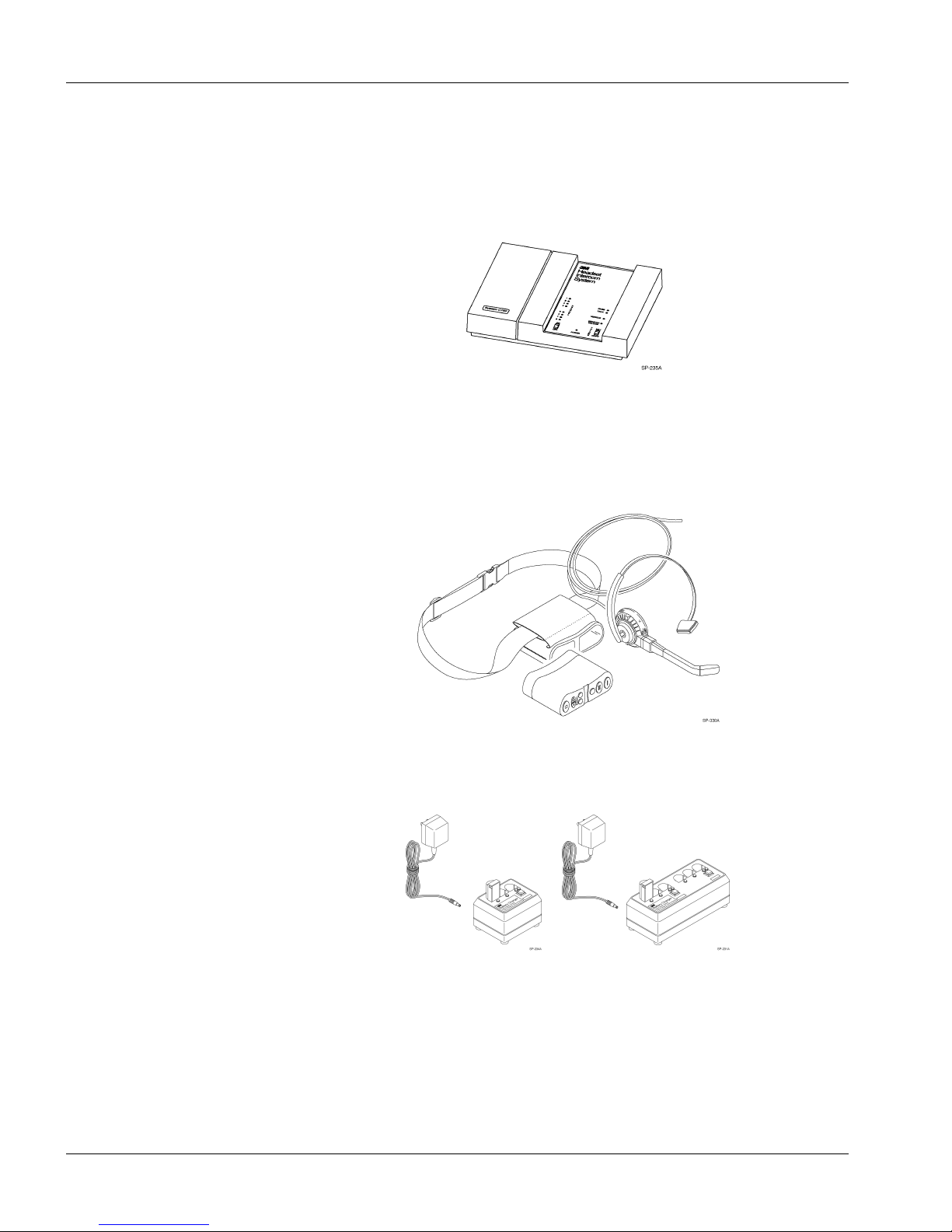
The base station is the interface between the customer and the belt pack worn by
the operator. See Figure 1.
Figure 1. Base Station
The belt pack is used by the operator to communicate with customers and with
other store personnel who are wearing belt packs.
The headset is connected by a communications cable to the battery-powered belt
pack. See Figure 2.
Figure 2. Headset and Belt Pack
Battery Charger
2 3M 2003 January
The battery charger charges batteries in approximately 1.5 to 2 hours. The
charger is available in 3-slot and 6-slot versions. See Figure 3.
Figure 3. 3-Slot and 6-Slot Battery Chargers
Page 9
Model C860 Controls and Indicators
5 N
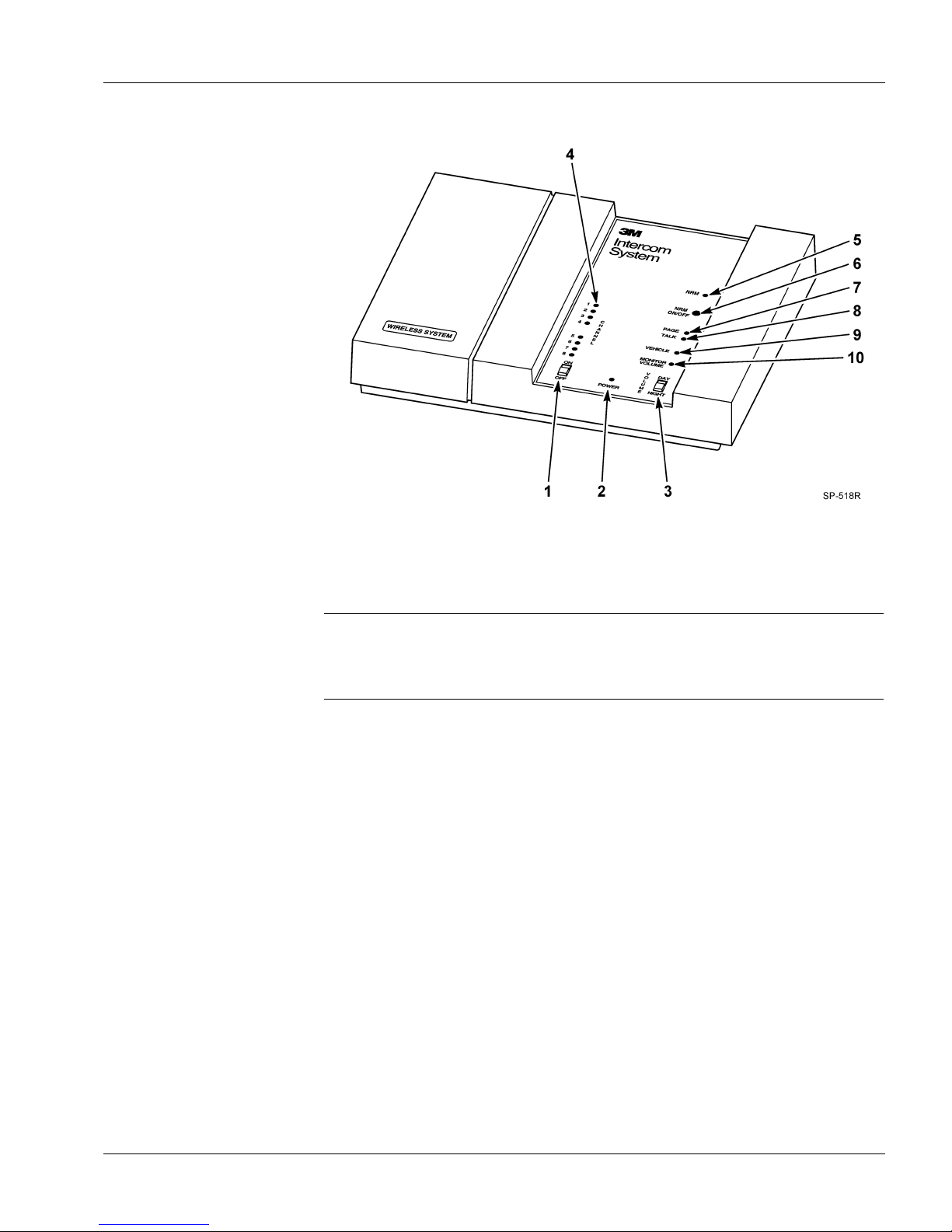
Base Station
1 ON/OFF Switch
The base station controls and indicators are shown below.
Figure 4. Base Station Controls and Indicators
The ON/OFF switch controls power to the base station.
2 POWER Indicator
3 VOLUME
DAY/NIGHT
Switch
4 Channel Indicators
RM Indicator
6 NRM On/Off
Button
7 Page Indicator
8 Talk Indicator
9 Vehicle Indicator
10 Monitor Volume
Access
This indicator lights when the ON/OFF switch is in the ON position.
Note
If for some reason the C860 headset system does not operate and the system
includes an optional wired backup system, turn off the C860 Base Station to
enable the backup system.
With the switch in the DAY position, the volume of the menu sign speaker is
increased for daytime operation. With the switch in the NIGHT position, the
volume of the menu sign speaker is decreased for nighttime operation. (Sound
travels further and more efficiently at night.)
These indicators light to show which of the 8 channels is selected.
This indicator blinks when the Noise Reduction Module is switched on.
This button turns the optional Noise Reduction Module on or off.
This indicator lights when headset Page communications occur.
This indicator lights when headset–to–menu sign “Talk” communications occur.
This indicator lights when a vehicle is detec ted at the menu sig n.
This access hole allows for adjusting the volume of the optional monitor
speaker.
3M 2003 January 3
Page 10
Controls and Indicators Model C860
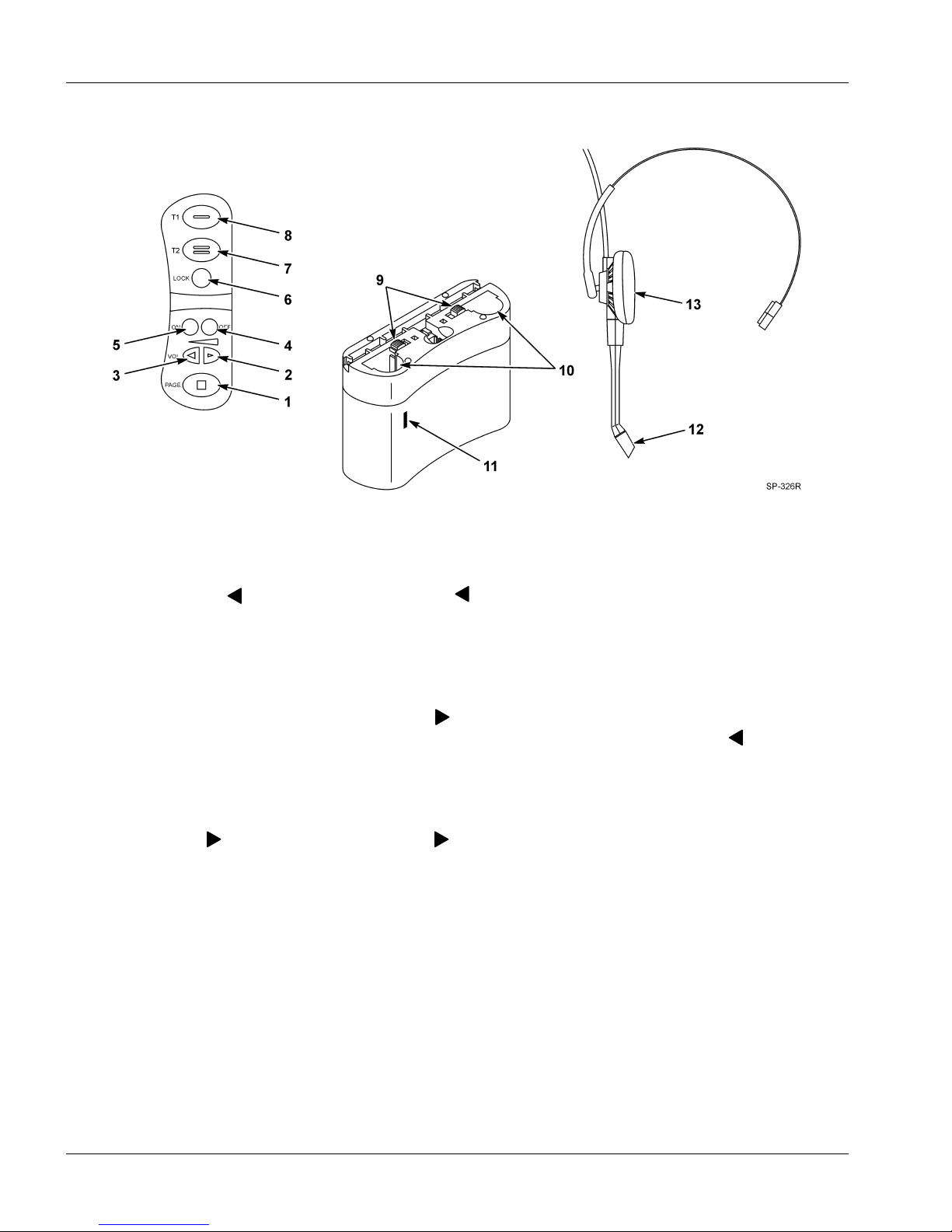
Headset and Belt Pack
1 Page Switch
The controls on the belt pack are shown below.
Figure 5. Controls
Press and hold the Page switch to talk to internal personnel without being heard
by the customer. Release the switch to listen.
2 Volume Down
Control
3 Volume Up
Control
4 ON Switch
5 OFF Switch
6 Talk Lock Switch
(Hands Free)
7 T2 (Talk Lane 2)
Switch
Press the volume down control to decrease the volume.
When either volume control is pressed, the headset emits a short tone to indicate
the new volume level. There are 15 different volume levels from minimum to
maximum.
If the headset volume is at its maximum level, a low, continuous tone sounds
when the volume up control is pressed. A low, continuous tone also occurs
when the volume reaches minimum level and the volume down c control is
pressed.
Note that even when set to its lowest level, headset volume is not turned
completely off.
Press the volume up control to increase the volume in the headset earpiece.
Press the ON switch to turn on the belt pack.
Press the OFF switch to turn off the belt pack.
For duplex systems where hands free operation is desired, press the talk lock
switch once to talk and listen to the customer. This enables hands-free
operation.
For dual-lane systems, press and hold the T2 (Talk Lane 2) switch to talk to the
customer at the menu sign in lane 2. Release the switch to listen.
For single-lane systems, both switches operate identically.
4 3M 2003 January
Page 11

Model C860 Controls and Indicators
8 T1 (Talk Lane 1)
Switch
9 Battery Release
10 Battery
11 Programming Jack
12 Microphone
13 Earphone/Earpad
Press and hold the T1 (Talk Lane 1) switch to talk to the customer in lane 1.
Release the switch to listen.
Push the battery release toward the center of the unit to release the battery.
This rechargeable battery provides power to the control unit.
This jack accepts the programming cable from the base station to allow the belt
pack to be programmed to the same radio channel as the base station.
The microphone sends the operator’s voice to the customer and/or other headset
operators.
The earphone is a speaker that broadcasts the voice from the customer or other
headset operators. The replaceable earpad covers the earphone and cushions the
operator’s ear to provide com fort.
3M 2003 January 5
Page 12

Controls and Indicators Model C860
Battery Chargers
The 3-slot and 6-slot battery charger controls are shown below.
Figure 6.
1 Charging Slots
2 Conditioning
and/or
Charging Slot
3 Charging Status
Indicators
4 Conditioning
Button
5 Conditioning
Status Indicator
6 Power Supply Jack
7 Power Supply
The charging slots hold batteries during the recharging cycle.
This dual-function slot holds a battery during conditioning and recharging
cycles. This slot functions as a conditioning slot when the conditioning button is
pressed.
The charging status indicators light RED, GREEN, or ORANGE to indicate
charging status:
RED indicates the battery is being charged.
GREEN to indicate the battery is fully charged.
ORANGE to indicate the battery is defective.
Press the conditioning button to condition a battery that is inserted in the
conditioning/charging slot. The button must be pressed within 2 seconds of
inserting the battery.
The conditioning status indicator lights YELLOW to indicate the battery in the
conditioning slot is being conditioned.
This jack accepts the plug from the power supply cord.
The power supply provides power to the battery charger.
6 3M 2003 January
Page 13

Model C860 Headset/Belt Pack Preparation
Introduction
Checking the
Headset for
Proper Fit
To prepare the headset for use, you will need to check the headset for proper fit.
To ensure effective operation and comfort:
• Adjust the headband width by gently bending the headband.
• Position the ear pad and microphone.
Positioning the
Microphone
Figure 7. Headband Size
Position the microphone so that its tip is near the corner of your mouth. See
Figure 8.
Figure 8.
3M 2003 January 7
Page 14

Headset/Belt Pack Preparation Model C860
Connecting the
Headset to the Belt
Pack
To connect the headset to the belt pack:
1. Insert the communications plug at the end of the headset cable into the
modular jack in the bottom of the belt pack. See Figure 9.
2. Press the cable into the cable channel on the bottom of the belt pack. See
Figure 9.
• Direct the cable toward the Page button to wear the belt pack on the
right hip.
• Direct the cable toward the Talk Lane 1 button to wear the belt pack on
the left hip.
Installing the Belt
Pack
Figure 9. Connecting the Headset to the Belt Pack
To install the belt pack into the belt pack:
1. Open the flap at the bottom of the belt pack.
2. Insert the belt pack face up (so that the controls are accessible through the
openings on the belt pack top). See Figure 10.
3. Extend the headset cable as follows:
• Toward the Page button to wear the unit on the right hip.
• Toward the Talk Lane 1 button to wear the unit on the left hip.
4. Close the flap.
8 3M 2003 January
Page 15

Model C860 Headset/Belt Pack Preparation
Wearing the Belt Pack
Figure 10. Installing the Belt Pack
The belt pack can be worn on either hip.
To wear the belt pack on the left hip, slide the belt through the belt holder slot
until the buckle of the belt is at the front of the body and the unit is on the left
hip. See Figure 11.
To wear the belt pack on the right hip, slide the belt through the belt holder slot
until the buckle of the belt is at the front of the body and the unit is on the right
hip. See Figure 11.
3M 2003 January 9
Figure 11.
Page 16

Operation Model C860
System Startup
Turning On the Base
Station
Turning On the Belt
Pack
Operating Modes
Standby Mode
Talk/Listen Mode
System startup includes turning on the base station and each belt pack that will
be used.
To turn on the base station:
1. Slide the power ON/OFF switch to the ON position. Check to see that the
POWER indicator lights.
2. Slide the VOLUME switch to the desired position (DAY or NIGHT).
To turn on the belt pack, press the ON switch located on the belt pack. A single
tone will sound in the headset to indicate the unit has been turned on.
The system has several operating modes. The number of available operating
modes depends on the system configuration (single-lane vs. dual-lane, standard
communication vs. duplex co mm unica tion , etc.).
In the standby mode, the belt pack is on and waiting to receive communication
from the customer or other headset operators. This mode is available with all
system configurations.
Use the talk/listen mode to talk to the customer. This mode is available with all
system configurations.
Single-Lane Standard or Duplex Communication Systems
1. A single beep alert tone sounds in the headset at 2-second intervals when the
system detects a customer (vehicle) at the menu sign.
2. When you hear the alert tone, press and hold T1 or T2 to talk to the
customer at the menu sign. Release T1 or T2 to listen.
Dual-Lane Standard or Duplex Communication Systems
In dual-lane systems, some belt packs are programmed to communicate with
Lane 1 and others are programmed to communicate with Lane 2.
1. An alert tone sounds in the headset when the system detects a customer
(vehicle) at the menu sign:
• The alert tone for Lane 1 headsets is a single beep that repeats at
2-second intervals.
• The alert tone for Lane 2 headsets is a double beep that repeats at
2-second intervals.
2. When you hear the single beep alert tone, press and hold T1 and talk to the
customer. Release T1 to listen.
When you hear the double beep alert tone, press and hold T2 to talk to the
customer. Release T2 to listen.
Cross-Lane Communication Systems
Communication During Peak Hours
During peak hours, the cross-lane module is turned off and the system functions
like a dual-lane duplex system. Some belt packs are programmed to
communicate with Lane 1 and others are programmed to communicate with
Lane 2.
10 3M 2003 January
Page 17

Model C860 Operation
Communication During Off-Peak Hours
During off-peak hours, the cross-lane module is turned on to enable a single
operator to communicate with customers in either lane (1 or 2).
1. An alert tone sounds in the headset when the system detects a customer
(vehicle) at the menu sign:
• The alert tone for Lane 1 belt packs is a single beep that repeats at 2-
second intervals.
• The alert tone for Lane 2 belt packs is a double beep that repeats at 2-
second intervals.
2. When you hear the single beep alert tone, press and hold T1 and talk to the
customer at menu sign 1. Release T1 to listen.
When you hear the double beep alert tone, press and hold T2 to talk to the
customer at the menu sign 2. Release T2 to listen.
Talk Lock Mode
(“Hands Free”)
Use this mode to operate “hands free.” The talk lock mode is only available
with duplex system configurations.
In this mode, the belt pack automatically switches from standby to talk/listen
when a customer is detected. The belt pack automatically switches back to
standby when the customer leaves.
Note
“Hands free” operation (talk lock mode) prevents all other headset operators
from talking. “Hands free” will not work in cross-lane mode.
To use the talk lock mode, press the talk lock switch on the belt pack. To return
to normal operation, press T1 or P.
3M 2003 January 11
Page 18

Operation Model C860
Page Mode
Page Monitor Mode
Use this mode to talk to other operators who are wearing headsets without being
heard by the customer at the menu sign. This mode is available with all system
configurations.
To page another operator, press and hold the page switch while speaking.
Release the page switch to listen.
Note
If you are not a menu sign operator, do not use the page mode while the menu
sign operator is communicating. Doing so may interrupt or prevent
communication between the menu sign operator and the customer.
Use this mode to listen for pages from other operators (without hearing the
communication to and from the customer). This feature is convenient for
managers who only want to hear page communication. This mode is available
with all system configurations.
To use the page monitor mode:
1. Turn the belt pack OFF. See Figure 12.
2. Press and hold the page button while pressing and holding the ON button,
12 3M 2003 January
Figure 12. OFF Switch
up to 5 seconds, until audible tones are heard. This locks the belt pack in
the page monitor mode. See Figure 13.
Page 19

Model C860 Operation
Figure 13. Page Switch and OFF Switch
To respond to a page, press P (page switch).
To return to normal operation:
1. Turn the belt pack OFF.
Special
Considerations
2. Turn the belt pack ON.
When using the talk/listen mode or the page mode, keep the following things in
mind:
• Communication between the operator and the customer may be heard by
several people.
• Only one operator can talk at a time.
• In the talk/listen mode, communication from the belt pack is heard by
customers and other operators who are wearing headsets.
3M 2003 January 13
Page 20

Maintenance Model C860
Belt Pack
Replacing the Battery
When the battery voltage is too low, the headset sounds a short, low-volume
tone at seven-second interv als to alert the oper ato r to insta ll a fu lly charg ed
battery. The “battery voltage low tone” continues for two minutes after which
the belt pack turns off automatically to prevent damage to the batteries.
Note
When installing a battery, make sure it is fully charged. It is important to
remember that an unused C860 battery loses five percent of its charge per
week. If a battery has not been used for several weeks, make sure to charge
prior to use.
To replace the battery:
1. Push the battery release to release the battery. See Figure 14.
2. Remove the discharged battery from the belt pack.
3. Insert a fully charged battery in the unit. Make sure the battery is fully
inserted (battery release clicks). See Figure 14.
Note
The C860 can operate on one battery or two. Using two batteries doubles the
operating time between charges.
If two batteries are used, both must be recharged at the same time.
Replacing the Headset
Pad
14 3M 2003 January
To replace the headset pad, remove the worn/damaged ear pad from the ear cup
and replace it with a new pad.
Figure 14.
Page 21

Model C860 Maintenance
Battery Charger
Location
Cleaning the Contacts
Batteries
Care, Handling and
Storage
Battery Voltage Low
Tone
Charging Batteries
The battery charger should be placed on a flat surface such as a desktop or table
in a clean, dry environment, or an optional wall mount unit may be used.
If the indicators fail to light during charger operation, clean the contacts using an
alcohol-moistened cotton swab.
Avoid dropping batteries. Do not carry batteries in your pockets or leave them
in hot, damp or dirty places.
!
Caution
Be careful not to short the battery contacts together.
When the battery voltage becomes too low, a short, low-volume tone sounds in
the headset at seven-second intervals to alert the operator to replace with a fully
charged battery.
The “battery voltage low tone” continues for two minutes after which the
headset turns off automatically to prevent damage to the batteries.
To charge a battery, insert the battery in one of the charging slots as shown in
Figure 15.
• The indicator lights RED to indicate the battery is charging.
• The indicator lights GREEN to indicate the battery is fully charged.
• The indicator lights ORANGE to indicate the battery is defective.
Note
Discharged batteries require 1-1/2 to 2 hours to charge.
Figure 15.
3M 2003 January 15
Page 22

Maintenance Model C860
To condition a battery:
1. Insert the battery in the charging/conditioning slot as shown in Figure 16.
2. Press the conditioning button within 2 seconds after inserting the battery.
The indicator lights YELLOW to indicate the battery is being conditioned.
3. When the conditioning cycle ends, the Conditioning Status Indicator will
glow green.
Note
Conditioning leaves the battery in a charged state.
Disposing of Batteries
Making Sure Batteries
are Ready for Use
Important
Information about
C860 Rechargeable
Batteries
Figure 16.
To help protect the environment, C860 rechargeable batteries which have
reached the end of their useful life should be disposed of in accordance with
local requirements.
Follow these tips to make sure batteries are always ready for use:
• Have at least one extra battery for each belt pack. This helps ensure that a
fully charged battery is always available.
• Recharge a low battery as soon as it is removed from the belt pack.
• Keep the battery contacts clean: both those on the battery and those in the
belt pack. To clean the contacts, use an alcohol-moistened cotton swab.
• Remember that a battery recharge takes approximately 1-1/2 to 2 hours.
• Avoid removing and reinserting batteries while they are charging (charging
status indicator is RED).
• Remember that batteries discharge fastest during Talk and Page operation.
Avoid unnecessary communications.
Keep the following information in mind as you operate the system and as you
establish operating procedures:
• Avoid shorting across the battery contacts with metal items. Never carry a
battery in a pocket or place it in a drawer where it can accidentally be
shorted by keys, coins etc.
16 3M 2003 January
Page 23

Model C860 Maintenance
• Have adequate charging capacity for the number of belt packs in your
system. One battery charger will handle up to three belt packs. Use of more
than three belt packs requires an additional battery charger.
• Batteries perform best at moderate temperatures. Extremes of heat and cold
reduce their performance.
3M 2003 January 17
Page 24

Special Instructions for System Manager Model C860
Programming the
Belt Pack for
Cross-Lane
Operation
The belt packs are factory programmed for single-lane operation to enable the
operator to press either T1 or T2 to communicate with lane 1.
For cross-lane systems, the belt packs must also be programmed to enable
communication with either lane 1 or lane 2. With the cross-lane module turned
ON, the lane 1 or lane 2 operators can press T1 to talk to lane 1 customers or T2
to talk to lane 2 customers.
To program the belt pack for dual-lane cross-lane operation:
• While pressing and holding both the T1 and T2 switches on the belt pack,
turn the unit ON. Hold all three switches for at least 5 seconds. See
Figure 17.
• Audible tones will be heard in the headset earpiece, indicating that the belt
pack is programmed for dual-lane cross-lane operation.
Figure 17.
Reprogramming
18 3M 2003 January
If you no longer need the dual-lane cross-lane feature, reprogram the belt pack
by repeating the above procedure.
Page 25

Model C860 Special Instructions for System Manager
Changing Channels
if Interference is
Heard
The C860 system is capable of operating on any one of eight different channels.
If messages etc. from a different transmitter are heard in the headset or monitor
speaker, or if you are told that your store’s messages are being heard elsewhere,
interference is occurring. You can correct either type of interference by
changing the base station operating channel. To do this:
1. Pull outward on the right side of the base station half-cover and then lift and
remove the cover. See Figure 18.
Figure 18.
2. With the base station turned on, press and release the Channel Select switch
once. (This advances the system to the next channel.) One of the red
indicators (1-8) will light, indicating the newly selected channel.
3. Press the RESET switch to “read” the new channel selection into the
3M 2003 January 19
Figure 19.
microprocessor.
Note
When two systems are used in a cross-lane application, both base stations
must be set to the same channel, but different lane settings.
Page 26

Special Instructions for System Manager Model C860
4. With the belt pack turned ON, plug one end of the programming cable into
the belt pack programming jack. See Figure 19.
5. Plug the other end of the programming cable into the base station
programming jack. See Figure 19.
6. Audible tones will be heard in the headset earpiece, indicating that
programming is complete.
7. Repeat Steps 1 through 6 to program the rest of the belt packs.
The belt pack is now programmed to the same channel as the base station. If
interference continues to occur, repe at the chann el prog ram m ing procedure.
After seven channel changes, the original channel will again be encountered. If
none of the channels is interference-free, contact your local 3M InTouch
Products dealer.
Changing the
Day/Night Switch
Setting
Outdoors, sound travels best at night when air temperatures are cooler and
background noise is reduced. To allow you to reduce the volume of the menu
sign speaker to a lower, pre-set nighttime level, the base station has a VOLUME
DAY/NIGHT switch. See Figure 20.
Figure 20.
Normally, the VOLUME DAY/NIGHT switch is always left in the DAY
position.
However, if local ordinances require quieter nighttime operation of the menu
sign, move the VOLUME DAY/NIGHT switch to the NIGHT position.
20 3M 2003 January
Page 27

Model C860 Special Instructions for System Manager
Adjusting the
Monitor Speaker
Volume
If the system has an optional monitor speaker, adjust its volume using the
following procedure:
1. With the base station turned ON, insert a small straight-blade screwdriver
into the MONITOR VOLUME access hole. See Figure 20.
2. Turn the volume control clockwise to increase the volume or
counterclockwise to decrease it.
3M 2003 January 21
Page 28

Troubleshooting Model C860
Introduction
To use the following troubleshooting guide, locate the problem in the left
column and look for the problem’s possible causes and corrections in the middle
and right columns. Possible causes are listed in the order in which they are most
likely to happen. Check for possible causes in the given sequence to help isolate
the problem.
System
Troubleshooting
Problem Possible Cause Correction
No communications. One or more
headsets hear static.
The base station is defective. Call for authorized service.
The base station is not ON.
Base station and belt packs not
programmed to same channel.
Turn the base station ON. Make
sure that the power transformer is
plugged into the wall outlet and
the base station power receptacle. If
the red power light does not come
on, check for power at the wall
outlet. If power is OK, call for
authorized service.
Reprogram base station and/or belt
packs.
into
A single belt pack is dead. No
communication to or from customer.
No communications to or from other
belt packs (PAGE or TALK
functions). No static is heard.
The battery is discharged.
Belt packs do not go into standby
(silence) when the vehicle leaves the
menu sign.
Defective vehicle detector. Call for authorized service.
The monitor speaker does not
operate.
The belt pack is not turned on. Turn the belt pack on.
Replace the battery with a fully
charged one.
The headset is unplugged or
defective.
This is normal when an “air switch”
type of vehicle detector is in use.
There is a large metal object over
the loop in the driveway (if a loop is
used).
The base station internal monitor
volume control is turned too low.
Call for authorized service.
Momentarily press the PAGE switch
to return to standby.
Remove the metal object.
Increase the monitor speaker
volume setting. (Store manager
only.)
22 3M 2003 January
Page 29

Model C860 Troubleshooting
Problem Possible Cause Correction
No vehicle alert tone in headset.
The vehicle detector module is not
plugged into the power outlet.
Plug the vehicle detector module
into the power outlet.
The internal base station alert tone
Call for authorized service.
volume control is set too low.
Defective base station or vehicle
Call for authorized service.
detector module.
No communication to or from the
The base station is not turned OFF. Turn the base station OFF.
customer when using the backup
intercom.
No power to the backup intercom.
Turn the backup intercom ON
and/or plug its power transformer
into the wall outlet.
The volume controls on the backup
intercom are turned too low.
Turn the volume controls up to
increase volume.
Defective backup intercom. Call for authorized service.
“Low battery” tones are heard in
headset despite newly charged
Dirty contacts on the battery, belt
pack, or in the battery charger.
Clean the battery contacts with
alcohol.
battery.
Defective battery. Replace the battery.
Defective belt pack. Call for authorized service.
No TALK or LISTEN with known
System problem. Call for authorized service.
good belt pack.
Low volume from belt pack to
customer and other headsets.
Headset microphone not positioned
properly beside operator’s m outh.
Reposition microphone (see
Checking the Headset for Proper Fit
in Section 3).
Audio “cuts out” or is interrupted
when talking to customer or other
Interference.
Change channels and reprogram the
belt packs.
headsets.
Belt pack is too far from the base
Move closer to the base station.
station (out of range).
Defective belt pack or base station. Call for authorized serv ice.
No transmit to menu sign or other
transceivers when TAL K s witch is
Defective TALK switch or defe ctive
base station.
Call for authorized service.
pressed. PAGE communications
OK.
3M 2003 January 23
Page 30

Troubleshooting Model C860
Problem Possible Cause Correction
Short repeating tone at seven-second
intervals heard in headset, and then
belt pack turns off after two
minutes.
Dirty battery contacts. Clean battery contacts with alcohol.
This is normal operation when the
battery voltage becomes too low.
Battery and
Battery Charger
Troubleshooting
Problem Possible Cause Correction
Battery does not charge when
plugged into the battery charger.
Defective battery. Try a known good battery.
Either the battery contacts or the
contacts in the battery charger have
a dirt/grease buildup.
Recharge battery.
Clean battery/battery charger
contacts with alcohol and cotton
swab.
Defective battery charger. Call for authorized service.
Short battery life. Battery is/was not fully charged. Recharge battery.
Dirty battery contacts. Clean battery contacts with alcohol.
Battery needs to be reconditioned. Recondition battery.
LED does not turn red when a
battery is plugged into the battery
charger.
Battery charger not plugged in.
Defective battery. Try a known good battery.
Defective battery charger. Call for authorized service.
Dirty contacts on battery or in
battery charger.
Clean battery/battery charger
contacts with alcohol.
Check that the battery charger
transformer is plugged in and
connected to a “live” outlet.
24 3M 2003 January
Page 31

Model C860 Troubleshooting
Service
C860 system service needs can be fulfilled by your local 3M InTouch Products
dealer. If special service assistance or information is needed, please call
1-800-328-0033.
3M 2003 January 25
Page 32

Food Services Trade Department
3M Center
St. Paul, MN 55144-1000
Printed in U.S.A.
3M 2003 January
78-6912-0692-0 Rev. B
 Loading...