

Page 1
Advanced Systems
Tester
900AST Series
Coaxial Wire Testing
Technical Tip
December 2005
78-8135-6156-6-A
Page 2
3M™ Advanced Systems Tester 900AST Series
Setup for Use
Battery Requirement
The battery holder holds six “AA” standard alkaline
batteries and should be installed prior to using the
unit. Please see the 900AST tester manual or DVD
for battery installation instructions. Always initiate a
self-calibration after installing new batteries.
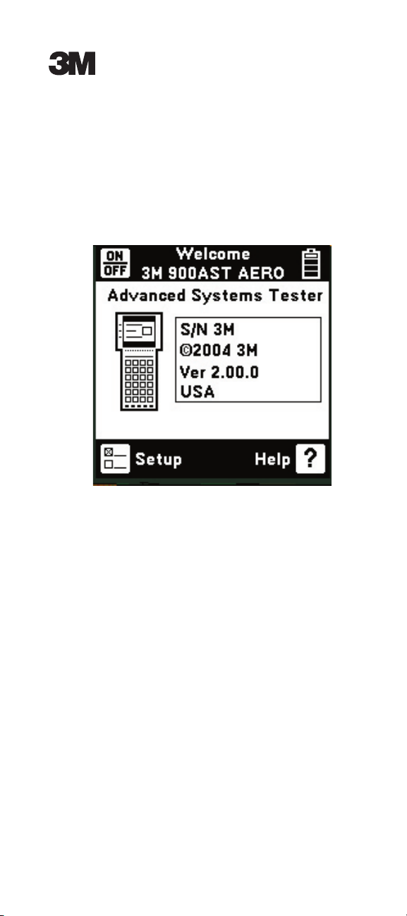
The battery symbol in the upper right-hand corner
of the display gives an indication of the approximate
battery capacity. Each bar represents one-quarter of
the full capacity.
Front Panel
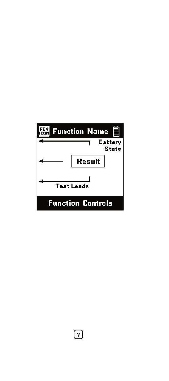
Test Leads
The test lead icons are shown on each of the
measurement screens and appear after a function or
test is selected. Each lead points to a color dot on
the front label that corresponds to the actual test lead
and test jack to be used. This on screen display is the
connection diagram for the selected test. The active
control keys are displayed on the bottom of the
screen and act as a guide through setup and testing.
For TDR applications using the special coaxial TDR
test lead(s), the test lead icons indicate which test
jacks (also denoted by colors) to use.
Operational Help
For operational information, refer to the 900AST
tester manual or “Help”
900AST tester keypad. For technical service,
warranty or repair questions, call 800 426 8688 (US
and Canada) or contact your local 3M representative.
control key on the
2
Page 3
3M™ Advanced Systems Tester 900AST Series
Keypad
The 900AST tester keypad has twelve yellow and
red “Control Keys” and nine blue “Function Keys”.
Additional blue keys on the keypad are reserved for
future expansion and have no designation or current
function.
Control Keys
Use the red and yellow keys to control and setup the
900AST tester and its functions.
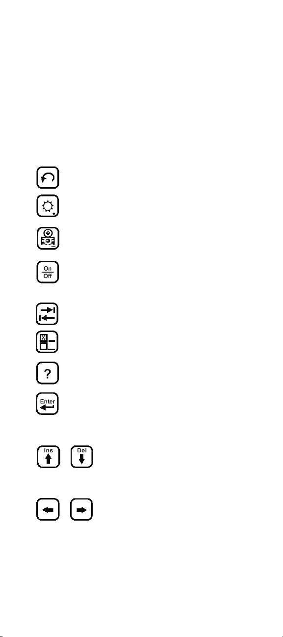
Use the [Return] key to return to a previous
step in a function.
Use the [Contrast] key to adjust the contrast
or to turn the backlight on or off.
Use the [Save] key for storing TDR traces.
Use the [On/Off] key to turn the 900AST
power on or off (also see “Power Down
Timeout”).
Use the [Tab] key to select between
different options.
Use the [Setup] key to change the setup of a
function.
Use the [Help] key to get context sensitive
help with any screen or function.
Use the [Enter] key to accept changes or
move to the next step in a function. To
insert a space to the left of the cursor press
enter.
Use the [Up] and [Down] keys to
scroll to different menu options
or insert/delete characters when
editing.
Use the [Left] and [Right] keys to
select different options or move the
TDR cursor
3
Page 4
3M™ Advanced Systems Tester 900AST Series
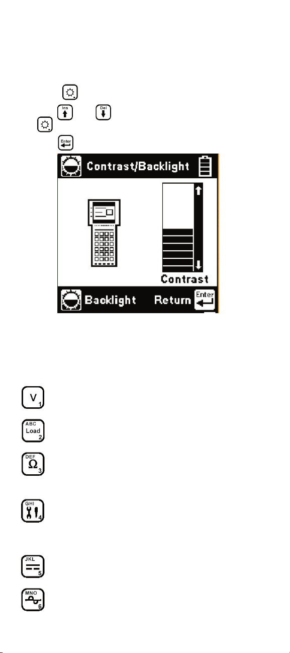
Contrast and Backlighting
Note: Use of backlight decreases available battery
capacity.
Press the
Use the
the key again to turn the backlight on or off.
Use the
key to display the contrast screen.
and
keys to adjust the contrast. Press
key to return to previous screen.
Function Keys
Use the blue keys to select the different tests in the
900AST tester. The blue keys become number or
letter keys when editing.
Use the [Voltage] key to measure DC or AC
voltage.
Use the [Load] key to measure the current
through a simulated load lamp.
Use the [Resistance] key to measure
resistance and access the ‘Soak Test’ and
‘Contact Resistance’ functions.
Use the [Toolbox] key to access: Self
Calibration, Stored Results, Special
Resistance, and the Ohms to Distance
Calculator
Use the [Capacitance] key to measure the
capacitance of a component or circuit.
Use the [Tone] key to send interrupted tone
for circuit identification.
4
Page 5
3M™ Advanced Systems Tester 900AST Series
Use the [RFL] key to find the distance to a
resistance fault between two conductors or a
conductor and ground.
This key is used for editing only.
Use the [TDR] key to activate the Time
Domain Reflectometer.
Use the [Auto] key to activate automatic
TDR trace analysis.
CAUTION
The 900AST tester is a tool for troubleshooting wiring
problems. It is not designed for troubleshooting electronic
circuits or instrumentation. The ohms, soak, contact
resistance, special resistance and RFL functions
generate a current limited (< 1 mA) 80V stimulus.
TDR and Auto TDR functions generate high-energy
electromagnetic pulses. Unexpected measurement
results and/or damage are possible if applied to
electronic circuits.
Circuit testing should be performed by personnel trained
in electrical safety practices and in accordance with
applicable safety standards.
Connecting to Coaxial Wires for Testing
Ensure that electrical power has been removed and
components disconnected from the wiring to be
tested before beginning wiring tests.
Note: For best operation, use the special coaxial
TDR test leads supplied with your 900AST
tester to perform coaxial wire TDR
measurements.
The TDR test cable has a standard male BNC
connector on the end. Plug the opposite end of the
TDR test leads plug into the Red/Black and/or Blue/
Yellow test jacks on the 900AST tester (one or more
cables may be used depending on the desired TDR
mode.)
Connect the end of the TDR test cable to the coaxial
wire to be tested. Use a BNC adapter (if needed) to
connect to the coaxial circuit under test.
5
Page 6
3M™ Advanced Systems Tester 900AST Series
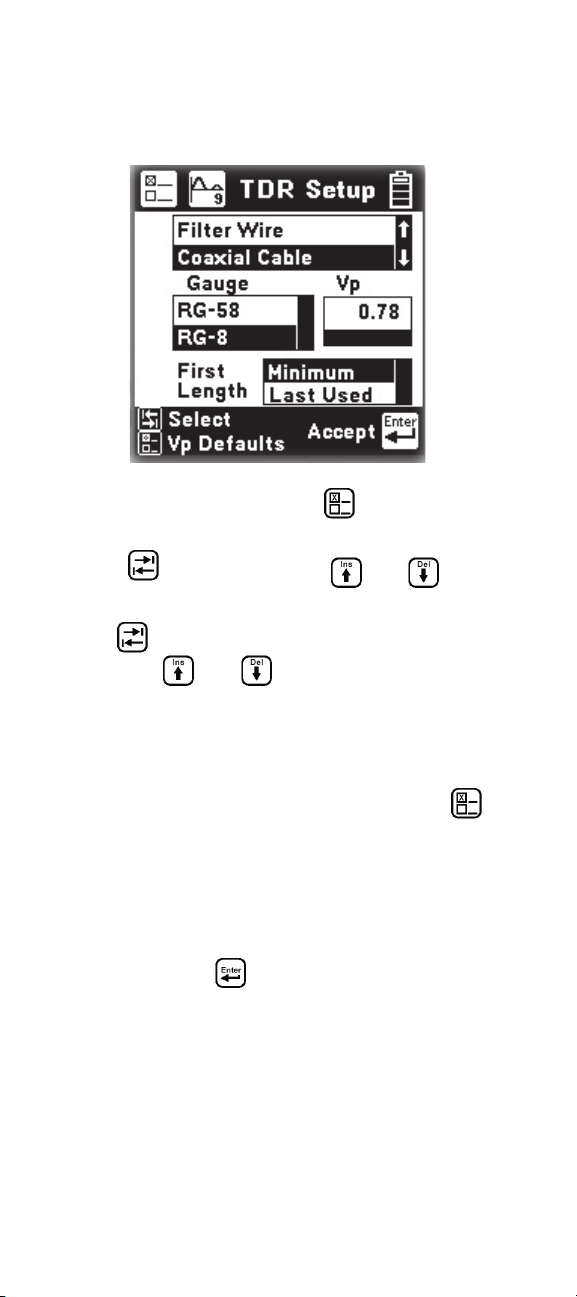
TDR Setup
The TDR features a setup function that allows you to
select the type of Coaxial wire to be tested.
From the TDR Menu, press the Setup key to
enter the TDR Setup.
Press the select key and the and arrow
keys to highlight coaxial cable for wire type.
Use the
box. Use the
select key to move to the wire gauge
and keys to highlight the type
of coaxial cable to be tested and select ‘minimum
possible’ or ‘last used’ initial measurement length
setting.
Note: The 900AST tester maintains modified Vp
settings in internal memory. Press the
key in the TDR Setup screen to restore
original default Vp settings for all wire types.
Use the blue numeric keys changes the velocity
factor for the selected coaxial wire type or use the
default setting.
Press the enter key
to accept changes and
proceed.
6
Page 7

3M™ Advanced Systems Tester 900AST Series
TDR Test Modes
Press the or keys to move to the desired
mode.
Press the key to accept the highlighted mode
and start the measurement.
Single Trace
Use the TDR Single Trace mode to test a single
coaxial wire or circuit.
7
Page 8

3M™ Advanced Systems Tester 900AST Series
Dual Trace
Dual Trace is used to compare two coaxial circuits at
the same time (usually a faulted and a good circuit).
Connect the TDR test leads to the (Red and Black
jacks) and connect the second TDR test lead set
(Blue and Yellow jacks) to the reference circuit.
This mode is valuable when testing a system with
multiple coaxial wires serving the same system.
Memory
Memory mode is used to compare a circuit under
test to a stored trace in memory. The first screen in
memory mode will show a list of the ID numbers for
all stored TDR traces. Use the
highlight the desired stored result.
and keys to
Press the key to select the highlighted result and
display the stored results list for that ID number by
type (TDR), date and time.
You can delete individual stored results by pressing
the key.
8
Page 9

3M™ Advanced Systems Tester 900AST Series
Use the and keys to highlight the desired
stored result. Press the
key to display the stored
trace on the bottom of the TDR screen and the
“live” trace on the top. You may move the cursor by
using the
and keys.
The control settings for the stored trace can be
viewed by pressing the
or keys but the
settings cannot be changed.
The TDR Memory function includes a Difference
(‘Diff’) control, accessible from the memory screen
by pressing the
Control OFF. Use the
key. The default is Difference
and arrow key to turn
the Difference Control ON. Diff combines the live
trace with the stored trace to show the difference in
the two readings.
Peak
Use the TDR Peak mode to capture events that
may be intermittent. The ‘live’ trace is displayed
continuously. As a new maximum or minimum trace
is detected, it will replace the previous one on the
display.
If the circuit being tested is stable (no intermittent
faults), then the minimum, maximum and “live”
traces should appear as a single trace.
Note: If any of the control values are changed, the
peak histories will be erased and new values
will begin to display.
9
Page 10

3M™ Advanced Systems Tester 900AST Series
Length allows you to set the distance (or span) from
the left side of the screen to the right side. The left
side of the screen is at the end of the BNC test lead
and the right side is the farthest distance that can be
displayed with the selected length
Use the or keys to move forward or
backward through the TDR controls. Use the
and keys to change the parameters for the
control selected.
Available controls are Length, Filter, VP, Pulse, and
Gain. Individual controls and their parameters are
described in the 900AST Series Instruction Manual.
Move Cursor
Note: The 900AST tester automatically compensates
for the length of the special TDR test leads.
Zero distance is at the end of the test lead
BNC male connector.
Always place the cursor to the left side of an event
to mark its location. Use the
and arrow
keys to move the cursor across the screen. The
distance from the 900AST tester to the cursor is
always shown in the center of the distance bar. The
left side of the screen is at the end of the test leads,
and the right side is the farthest distance that can be
displayed with the selected length.
TDR Save for Coaxial Wiring Comparison
Approximately 200 TDR screenshots can be saved.
You can save only the active “Single Trace” TDR
screen.
Select the TDR control parameters so the screen
displays the trace as desired.
10
Page 11

3M™ Advanced Systems Tester 900AST Series
Press the key.
The 900AST tester will display the Save Results
screen as follows:
Use the blue keys to enter an alphanumeric ID. The
ID may have up to twelve digits. Whether a number
or letter is entered depends on how many times the
key is pressed. As an example, if the Ohms key is
pressed once, the number “3” will be displayed. If
the same key is pressed twice, the letter “d” will be
displayed.
Use the
arrow to position the cursor under the
first space and enter the first character, and then
use the
arrow to move the cursor under the next
space.
Insert the next character and use the
cursor
again to position the cursor to the next position.
Continue entering numbers or letters in this manner
until all have been entered.
Use to insert a space to the left of the cursor.
To delete a character, press the
key.
Use to add a ‘dash’ in a record name.
Once the ID has been entered, press the
key to
save the current TDR trace information.
Event Recognition
Events are the “dips” and “peaks” seen on the screen
caused by faults or changes (such as an open circuit
or short) on the conductor or pair. Connectors
11
Page 12

3M™ Advanced Systems Tester 900AST Series
generally cause small upward peaks due to a change
in impedance. To determine if an upward event is an
impedance change or a main event fault you may go
to the other end of the coaxial cable and disconnect
it. Next, take a jumper and short the inner conductor
to the outer shield. If you see a large downward
deflection in the trace the small peak is impedance
change. Conversely, if you can’t see the short or
downward deflection you have an open circuit in the
cable.
Target Contact
The first peak or dip on the screen is usually the
“target contact” which occurs at the point where
the 900AST tester connects to the circuit under test.
Since impedances of the different types of coaxial
conductors vary significantly, the initial event caused
by the 100-ohm TDR launch circuit contacting
the target can usually be ignored. Remember that
distance zero (0”) begins at the end of the test leads
for the TDR function. Should the dip after the initial
peak move significantly below the line you may have
a short at the shield termination point on the end
of the cable. Move to the other end of the coaxial
conductor and connect the tester leaving the first end
open. The end of the trace should produce an upward
deflection at the end of the cable. A downward
deflection may indicate a short.
Open Circuit
Any open circuit will show up as a peak on the
screen. A complete open will be the tallest peak you
will see. You cannot see events past a complete open.
12
Page 13

3M™ Advanced Systems Tester 900AST Series
Short Circuit
A short circuit (or zero-Ohm resistance fault) will
show up as the lowest dip on the screen. You cannot
see events past a short circuit
Branch Circuit
The beginning of the branch circuit will look like
a small dip and the end of the branch will look like
an open (upward peak). Use the 900AST tester
Resistance function to measure the resistance of
the conductors. If the resistance is high, you may
suspect a branch circuit.
Resistance Faults on Coaxial Cable
A resistance fault will show as a dip on screen. The
lower the value of resistance (or the closer to a zeroohm short), the lower the dip. Use the resistance
function to check the coaxial cable for a resistive
fault. Use the Soak test function to determine if the
resistive fault is caused by moisture, corrosion or if
it is purely resistive.
Soak Test
Use the Soak Test function to continuously measure
the insulation resistance of a coaxial conductor inner
conductor to shield.
13
Page 14

3M™ Advanced Systems Tester 900AST Series
Connect the 900AST test leads to the coaxial
conductor under test.
Press the
key to access the Soak test from the
Resistance screen.
Use the
key to save the active resistance to the
“Snap Shot” area.
Rising resistance in the active box typically indicates
moisture while falling resistance indicates corrosion.
Auto TDR for Coaxial Fault Detection
Use the Auto TDR function to have the 900AST
tester analyze and interpret a TDR coaxial cable
trace.
The Auto TDR function imports the coaxial
configuration selected in the TDR function using the
Setup key.
14
Page 15

3M™ Advanced Systems Tester 900AST Series
To change the coaxial configuration go to the TDR
function and press the Setup key.
Use the
and keys and the Blue numeric
keys to enter the length of cable to analyze. Enter a
length longer than the cable being tested but as close
as possible to the total length of the cable.
When the correct information is displayed on the
Auto TDR screen, press the
key to start the
analysis. The 900AST performs tests to determine
if the cable is shorted, open circuited, or has a
resistance fault.
Note: Auto TDR operates from a captured trace.
The trace is not ‘live’ as in the standard TDR
mode.
Auto TDR Resistive Faults
Note: Resistance faults are very difficult to detect
using TDR techniques. If a resistance fault
is detected, the 900AST tester prompts you
to consider using the RFL (Resistance Fault
Locate) function as shown below.
Auto TDR Trace Analysis
If the Auto TDR detects an open circuit, the cursor
is positioned at the location of the open circuit and
OPEN is displayed below the trace. If the Auto
TDR detects a short circuit or low resistance fault,
the cursor is positioned at the location of the short
circuit and SHORT is displayed below the trace.
15
Page 16

3M™ Advanced Systems Tester 900AST Series
In this case the low impedance anomaly at 24
inches is detected but not classified. The Auto TDR
displays ‘????’ below the trace.
Restoring the Aircraft After Testing/
Troubleshooting
Disconnect the 900AST TDR test cable from the
aircraft wiring. Also, remove any adapters (if
used). Ensure the other end of the coaxial cable is
reconnected. Reinstall the line replaceable unit or
component that was removed to accomplish testing
or troubleshooting and perform all applicable
maintenance manual procedures and operational
checks.
Care and Maintenance
Please see the 900AST Series Instruction Manual for
care and maintenance information.
16
Page 17

3M™ Advanced Systems Tester 900AST Series
This is the EU symbol for equipment that is covered
under the Waste from Electrical and Electronic
Equipment (WEEE) directive per CENELEC
Specification 5041. It indicates that certain products
should not be discarded in the trash, but rather
should be recycled. This applies to all electronic
pluggable and battery powered products.
3M is a trademark of 3M Company.
Important Notice
All statements, technical information, and recommendations
related to 3M’s products are based on information believed to
be reliable, but the accuracy or completeness is not guaranteed.
Before using this product, you must evaluate it and determine if
it is suitable for your intended application. You assume all risks
and liability associated with such use. Any statements related to
the product which are not contained in 3M’s current publications,
or any contrary statements contained on your purchase order
shall have no force or effect unless expressly agreed upon, in
writing, by an authorized officer of 3M.
Warranty; Limited Remedy; Limited Liability.
This product will be free from defects in material and manu
facture for a period of one (1) year from the time of purchase. 3M MAKES NO OTHER WARRANTIES INCLUDING,
BUT NOT LIMITED TO, ANY IMPLIED WARRANTY OF
MERCHANTABILITY OR FITNESS FOR A PARTICULAR
PURPOSE. If this product is defective within the warranty period
stated above, your exclusive remedy shall be, at 3M’s option, to
replace or repair the 3M product or refund the purchase price of
the 3M product. Except where prohibited by law, 3M will not
be liable for any indirect, special, incidental or consequential loss or damage arising from this 3M product, regardless
of the legal theory asserted.
-
Aerospace and Aircraft Maintenance Division
Transportation Business
3M Center, Building 220-9W-14
St. Paul, MN 55144-1000
1-800-364-3577 or 651-737-6501
www.3M.com/aerospace
17
78-8135-6156-6-A
© 3M 2005
 Loading...