

Page 1

3M™ Hot Melt Fiber Optic Connectors
ST, SC and FC
Instructions
June 2011
78-8073-7873-8-E
3
Find Quality Products Online at: [email protected]
www.GlobalTestSupply.com
Page 2

Contents
1.0 Safety and Helpful Hints ....................................................................................................................... 3
2.0 3M
3.0 3M
4.0 3M
5.0 3M
6.0 3M
7.0 3M
8.0 3M
™
Field Termination Kit Contents..................................................................................................... 4
™
Hot Melt ST Connector 900 µm Buffered Fiber .......................................................................... 6
™
Hot Melt ST Connector 3 mm Jacketed Cable ............................................................................. 8
™
Hot Melt SC Connector 900 µm Buffered Fiber ........................................................................ 10
™
Hot Melt SC Connector 3 mm Jacketed Cable........................................................................... 12
™
Hot Melt FC Connector 900 µm Buffered Fiber ........................................................................ 14
™
Hot Melt FC Connector 3 mm Jacketed Cable........................................................................... 16
9.0 Scribing ................................................................................................................................................ 18
10.0 Multimode Polishing: Hot Melt ........................................................................................................... 19
11.0 Singlemode Polishing: Hot Melt ......................................................................................................... 21
13.0 Finishing ............................................................................................................................................... 24
14.0 Field Termination Kit Replacement Part Numbers ............................................................................. 25
2
Find Quality Products Online at: [email protected]
www.GlobalTestSupply.com
Page 3
1.0 Safety and Helpful Hints
Use reagent grade isopropyl alcohol that is 99% pure to clean the fibers and other components. When terminating connectors on any cable
containing grease, ensure that all grease is wiped away and the buffer, coating, and fiber are thoroughly cleaned with isopropyl alcohol. Isopropyl
™
alcohol is not shipped with the 3M
Field Termination Kits; however, a bottle for the alcohol is included.
Note: Carefully follow safety, health and environmental information given on the container label or the Material Safety Data Sheet for the
isopropyl alcohol and 3M
™
Pronto™ Instant Adhesive, CA-8.
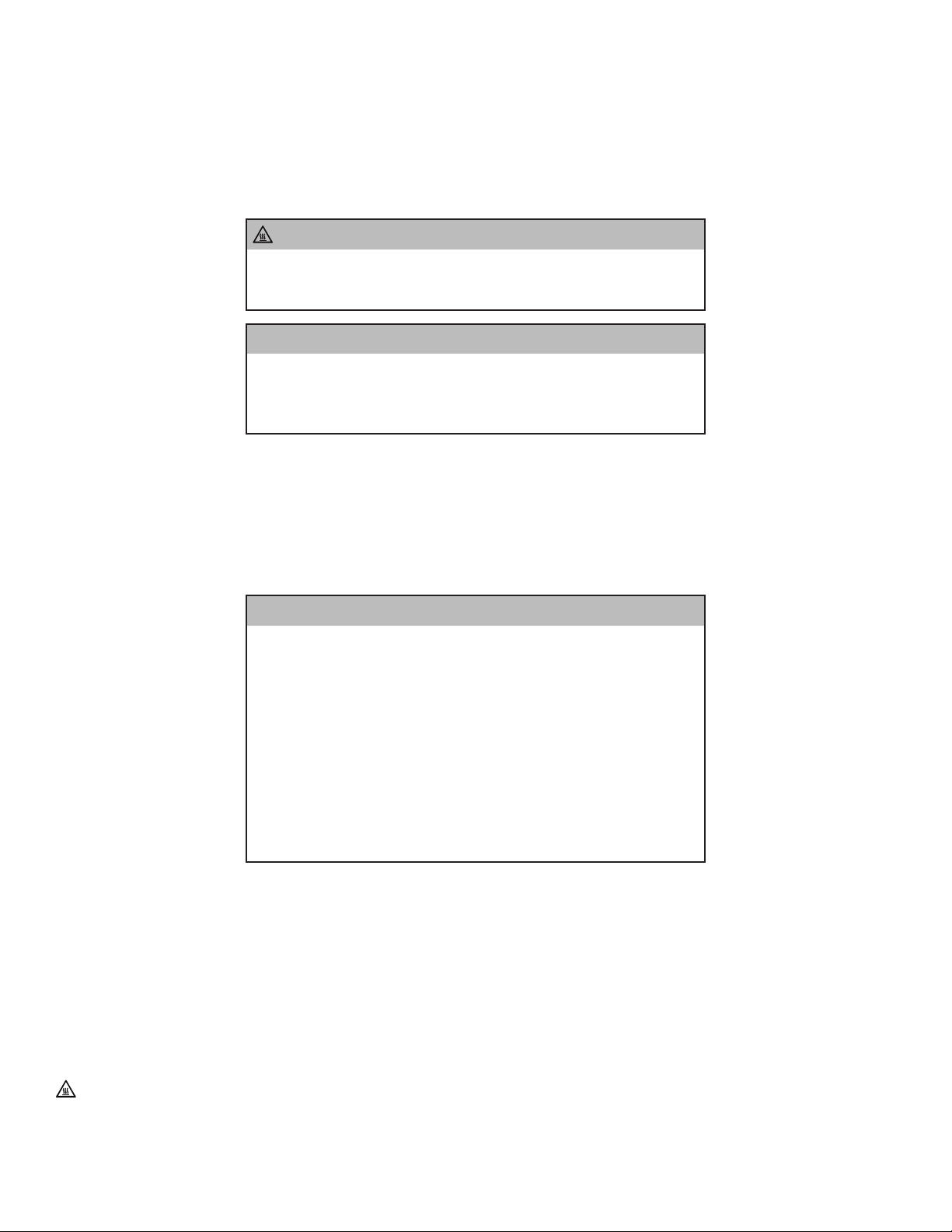
CAUTION
Hot Surface. The metal block in the Hot Melt Oven is heated to approximately 482°F (250°C).
Do not touch. Do not cover. Use only with original 3M™ accessories.
Note: Flashpoint of the Hot Melt glue is 520°F (271°C).
WARNING
• Safety glasses should be worn when working with optical fibers.
• Do not view fiber ends if they are illuminated with a laser.
• Keep oven clear from flammable material.
• Disconnect power supply when cleaning.
3M™ Hot Melt Oven Safety
Safety Information
This hot melt connector oven is intended for melting hot melt adhesive in 3M™ Hot Melt Connectors. It has been designed and tested for use only
™
with the 3M
Fiber Optic Connectors System. Other uses of this product may lead to poor performance or an unsafe condition.
WARNING
1. Power cord must be grounded and plugged into a grounded outlet.
2. Eye hazard. Do not view fiber ends if they are laser illuminated as eye damage may
result. Illuminate fiber ends with white light only.
3. Wear safety glasses.
4. No serviceable parts - return unit to the manufacturer for servicing.
5. For indoor use only.
6. To avoid possible environmental contamination, dispose of the unit in accordance with
applicable governmental regulations.
7. Avoid touching hot surfaces.
8. Avoid using unit near flammable materials.
9. When in use locate the unit where it can easily be unplugged.
10. The unit shall be cool before cleaning, and there shall be no flammable cleaning fluids
used.
Cooling and Cleaning
The device shall be cooled down before cleaned and there shall be no easily f lammable cleansing liquids used.
Explanation of symbols:
Warning - Refer to accompanying documents.
Caution - Risk of electric shock. Refer all servicing to manufacturer.
Caution - Hot Surface. The metal block in the Hot Melt Oven is heated to approximately 482°F (250°C). Do not touch. Do not cover. Use only
™
with original 3M
Find Quality Products Online at: [email protected]
Accessories. Note: Flashpoint of the Hot Melt glue is 520°F (271°C).
3
www.GlobalTestSupply.com
Page 4
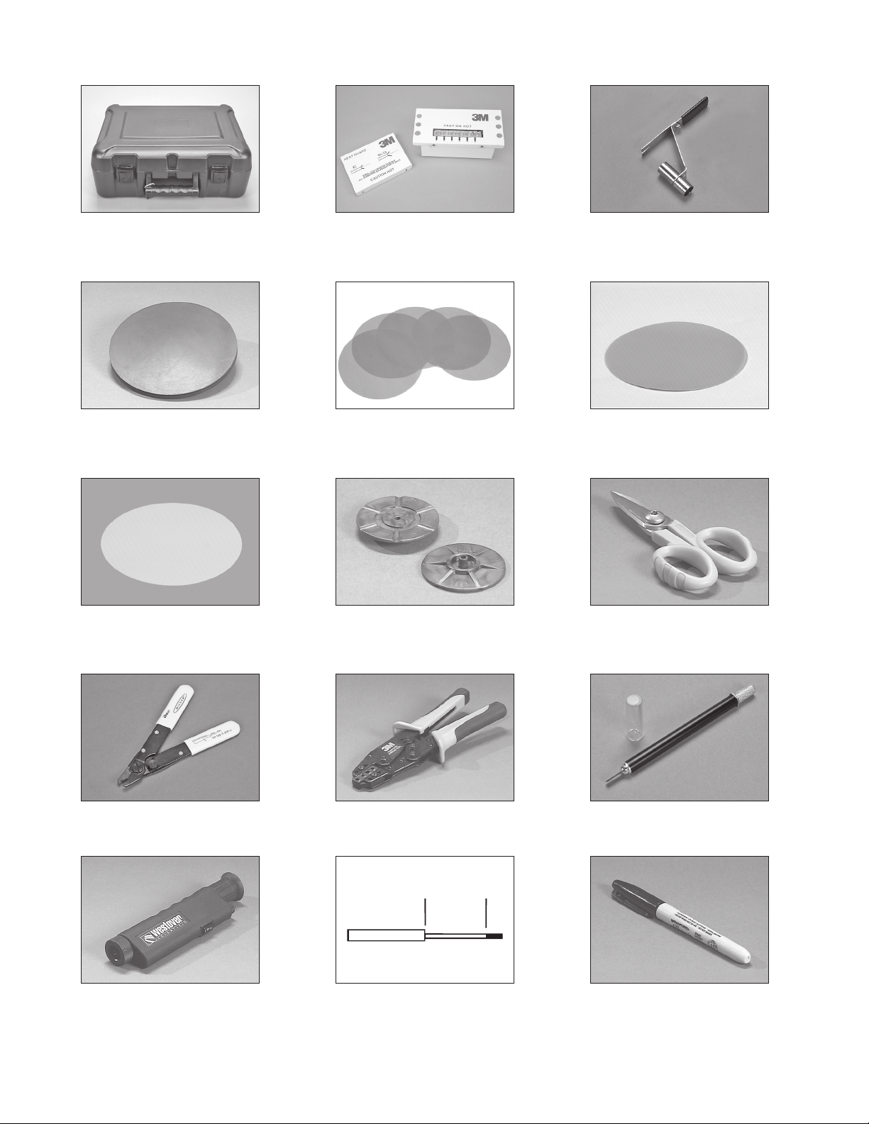
2.0 3M™ Field Termination Kit Contents
2.1 Carrying Case, 1 ea. 2.2 3M™ Hot Melt Oven 6312 (120 V) or 6323
2.4 3M™ Polishing Pad 6365-PP, 2 ea 2.5 3M™ Lapping Film 9 µm (gray), 10 sheets. 2.6 3M™ Lapping Film 2µm (pale green),
2.7 3M™ Final Polish Film 0.05µm (frost white),
20 sheets
(230 V) with heat guard, 1 ea.
2.8 3M™ Polishing Jig 8892, 2 ea. 2.9 3M™ Aramid Yarn Snips 6365-KS, 1 ea.
2.3 3M™ Universal Connector Holder 6365-HH,
6 ea.
50sheets
2.10 3M™ Stripping Tool 6362-TH, 1 ea. 2.11 3M™ Crimp Tool 6365-CT, 1 ea. 2.12 3M™ Fiber Scribe 6365-FS, 1 ea.
2.13 3M™ View Scope 6365-VS, 1 ea. 2.14 Strip Templates, 1 ea. 2.15 Fiber Marking Pen, 1 ea.
4
Find Quality Products Online at: [email protected]
www.GlobalTestSupply.com
Page 5
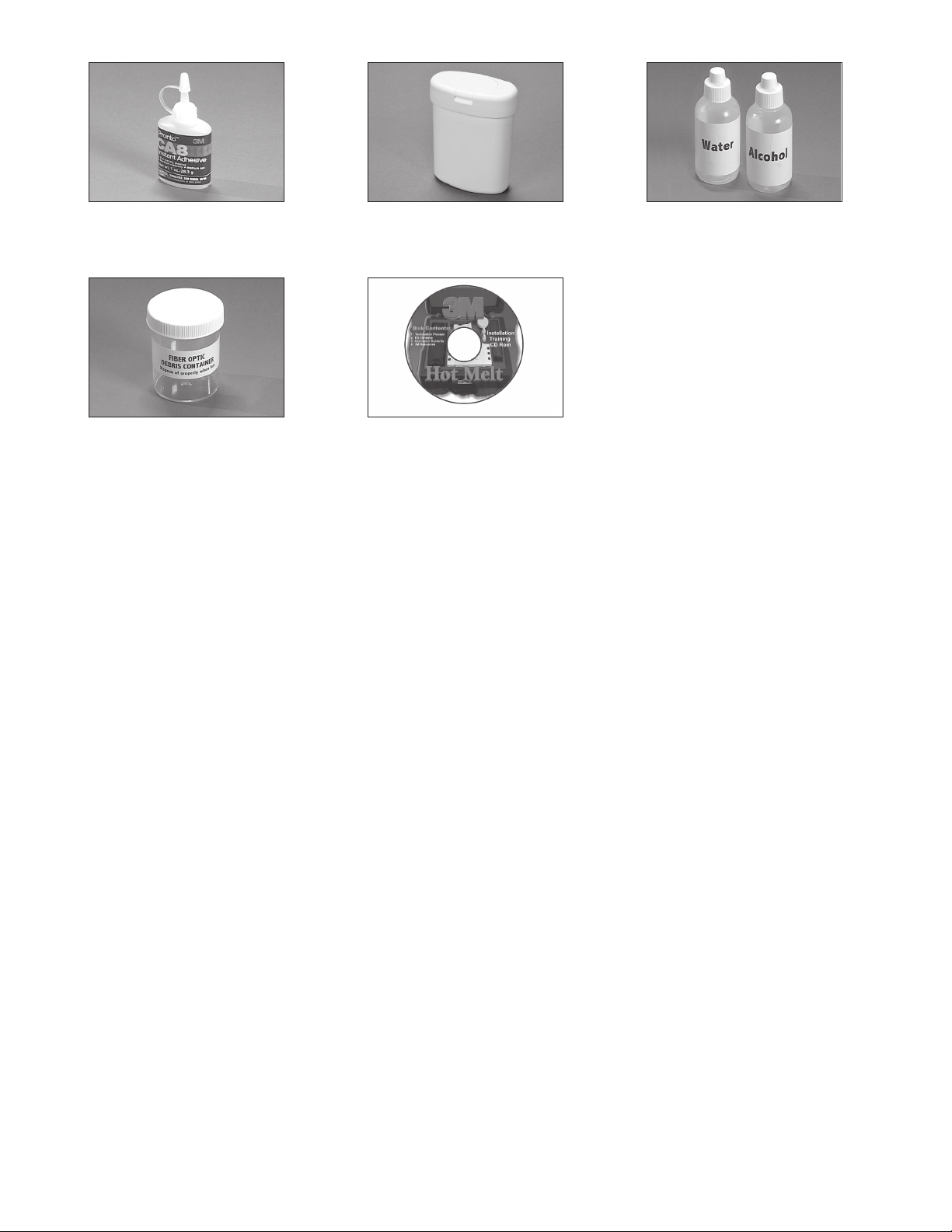
2.16 3M™ Pronto™ Instant Adhesive, CA-8, 1 ea. 2.17 3M™ Lint-Free Cloths 6366-CW, 100 pcs. 2.18 Alcohol and Water Bottles (shipped empty),
2.19 Fiber Scrap Can, 1 ea. 2.20 Training CD Rom, 1 ea.
1 ea.
5
Find Quality Products Online at: [email protected]
www.GlobalTestSupply.com
Page 6
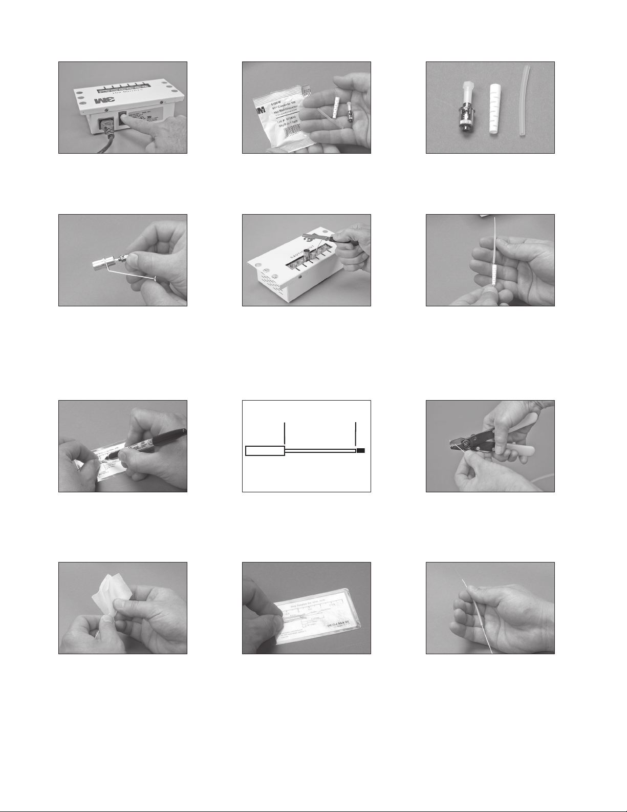
3.0 3M™ Hot Melt ST Connector 900 µm Buffered Fiber
7/8"
(22 mm)
A B C
3.1 Plug in the 120V or 230V power cord.
Turn on the 3M
™
Hot Melt Oven. The oven
requires six minutes to warm up.
3.4 Load ST Connector into the shorter end of
™
the 3M
Universal Connector Holder.
3.2 Open the connector package and remove
components.
3.5 Place the connector holder into an available
port in the oven.
Note: The hot melt connector should be in
the oven for at least 60 seconds. The
connector should not be in the oven
longer than five minutes.
3.3 Each connector package contains a
connector (A), strain relief boot (B), and
clear strain relief tube (C).
3.6 Place the strain relief boot and clear strain
relief tube on the buffered fiber, as shown.
3.7 Place the buffered fiber on the strip
template for “ST Hot Melt” and use the fiber
marking pen to mark the location of the
3.8 Strip Template 3.9 Using the 3M™ Stripping Tool 6362-TH,
remove the buffer in small pieces until 7/8”
(22 mm) of buffer has been removed.
buffer cut.
3.10 Using a lint free cloth moistened with
Isopropyl alcohol, clean the bare fiber to
remove any oils or Acrylate coating debris.
Find Quality Products Online at: [email protected]
3.11 Check the final strip lengths and adjust if
3.12 Position the clear strain relief tubing
necessary.
6
www.GlobalTestSupply.com
towards the end of the fiber where it will be
easily accessible.
Page 7
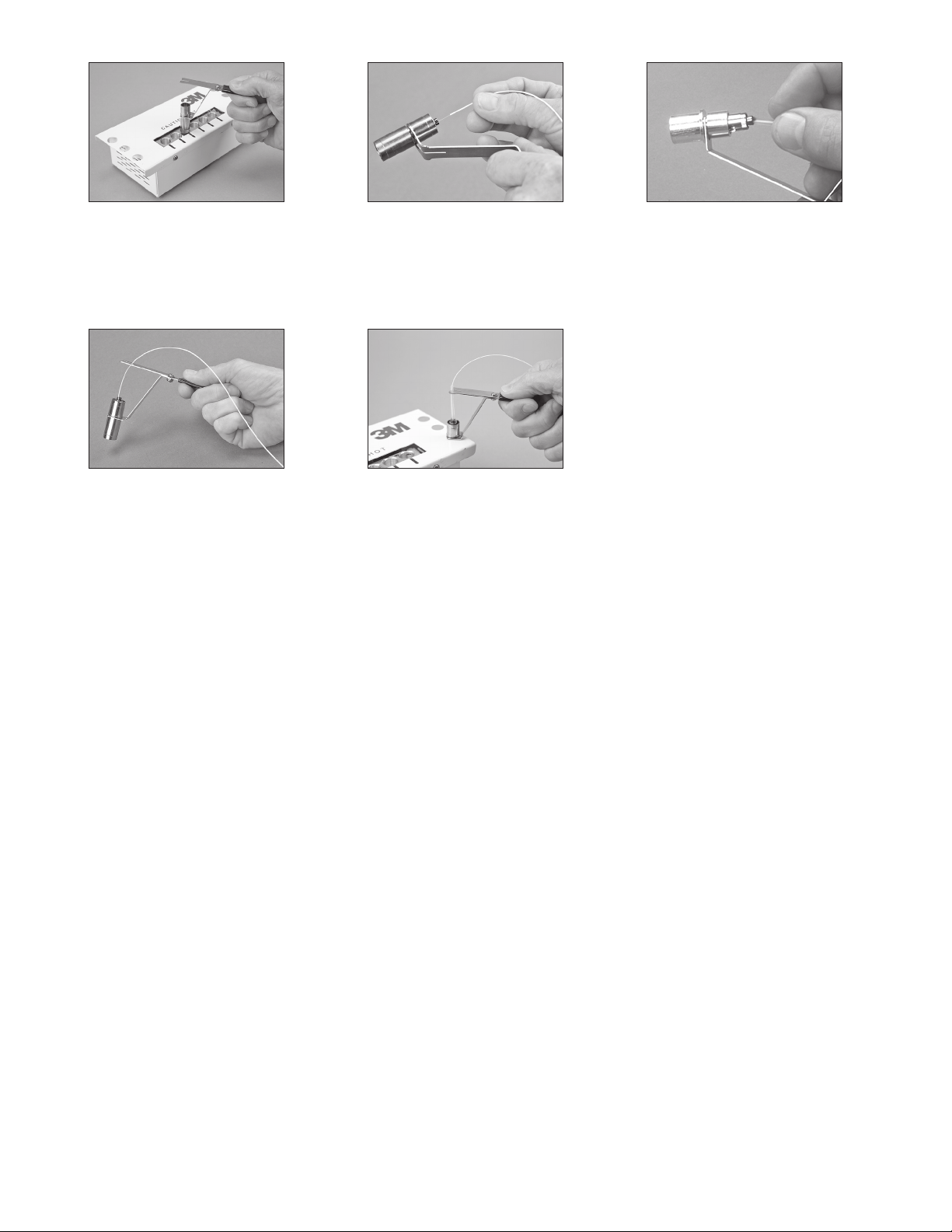
3.13 Remove the 3M™ Universal Connector
Holder from the 3M Hot Melt Oven by
grasping the cool-touch handle.
Caution: Do not touch the metal portion of the
holder or connector, as it will be hot!
3.14 Feed the fiber into the back of the 3M Hot
Melt ST Connector, until the buffer stops
inside the connector.
3.15 Slide the clear strain relief tube into the
connector until it stops.
3.16 Push the buffered fiber into the cable
retention feature until secure.
3.17 Rest the connector holder in one of the
available cooling ports located on both sides
of the oven. Let cool for three minutes.
Proceed to Section 9: Scribing, Page 18.
7
Find Quality Products Online at: [email protected]
www.GlobalTestSupply.com
Page 8
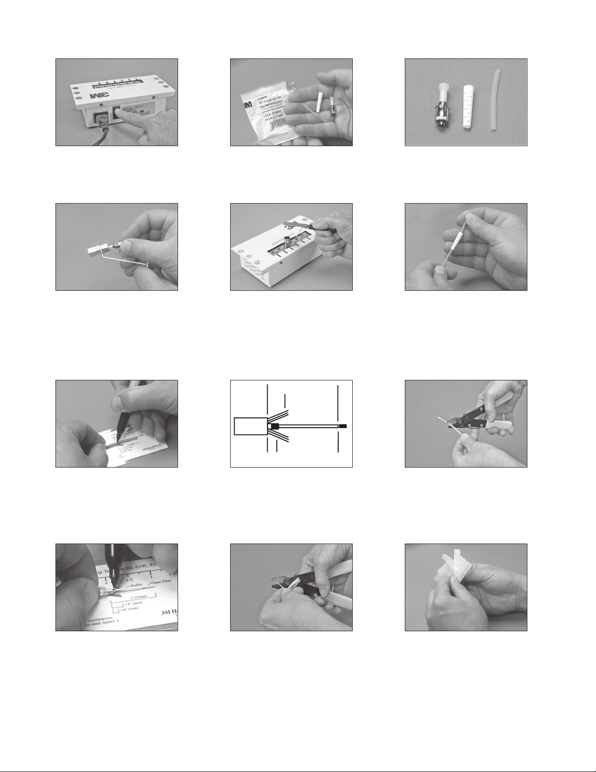
4.0 3M™ Hot Melt ST Connector 3 mm Jacketed Cable
1" (25 mm)
1/4"
(6 mm)
1/8”-3/16”
(1-3 mm)
7/8" Min. (22 mm)
4.1 Plug in the 120V or 230V power cord.
Turn on the 3M
™
Hot Melt Oven. The oven
requires six minutes to warm up.
4.4 Load ST Connector into the shorter end of
™
the 3M
Universal Connector Holder.
4.2 Open the connector package and remove
components.
4.5 Place the connector holder into an available
port in the oven.
Note: The hot melt connector should be in
the oven for at least 60 seconds. The
connector should not be in the oven
longer than five minutes.
4.3 Each connector package contains a
connector (A), strain relief boot (B), and
clear strain relief tube (C).
4.6 Place the strain relief boot on the jacketed
fiber, as shown.
4.7 Place the jacketed fiber on the strip
template for “ST Hot Melt” and use the
4.8 Strip Template 4.9 Using the 3M™ Stripping Tool 6362-TH,
score the jacket and remove by hand.
fiber-marking pen to mark the location
of the jacket cut, approximately 1" from
the end.
4.10 Fold back the Kevlar® fibers and mark
where the buffer should be stripped.
4.11 Using the 3M™ Stripping Tool, 6362-TH,
remove the buffer in small pieces until 1/8"
(3 mm) of buffer is protruding from the end
4.12 Using a lint free cloth moistened with
Isopropyl alcohol, clean the bare fiber to
remove any oils or Acrylate coating debris.
of the jacket.
Find Quality Products Online at: [email protected]
www.GlobalTestSupply.com
8
Page 9
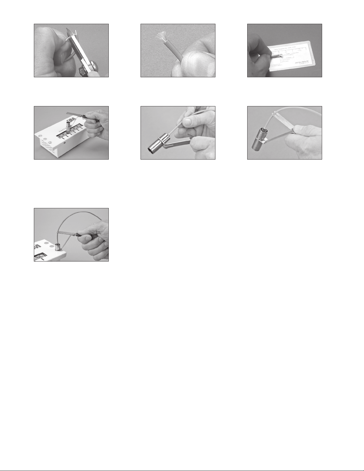
4.13 Gather the Kevlar® fibers to one side and
cut to length, approximately 1/4".
4.14 Flare the Kevlar® fibers equally around the
buffered fiber.
4.15 Check the final strip lengths and adjust if
necessary.
4.16 Remove the 3M™ Universal Connector
Holder from the 3M Hot Melt Oven by
grasping the cool-touch handle.
Caution: Do not touch the metal portion of the
holder or connector, as it will be hot!
4.19 Rest the connector holder in one of the
available cooling ports located on both sides
of the oven. Let cool for three minutes.
Proceed to Section 9: Scribing, Page 18.
4.17 Feed the fiber into the back of the 3M Hot
melt Connector, pushing until the Kevlar
®
fibers and jacket are secured inside the
connector.
4.18 Push the jacketed fiber into the cable
retention feature keeping the fiber as
straight as possible.
9
Find Quality Products Online at: [email protected]
www.GlobalTestSupply.com
Page 10
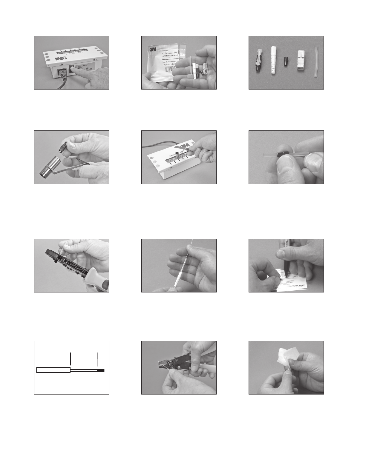
5.0 3M™ Hot Melt SC Connector 900 µm Buffered Fiber
A B C D E
5.1 Plug in the 120V or 230V power cord.
Turn on the 3M
requires six minutes to warm up.
5.4 Load the SC Connector into the longer end
of the 3M
™
Hot Melt Oven. The oven
™
Universal Connector Holder.
5.2 Open the connector package and remove
components.
5.5 Place the connector holder into an available
port in the oven.
Note: The hot melt connector should be in
the oven for at least 60 seconds. The
connector should not be in the oven
longer than five minutes.
5.3 Each connector package contains a
connector (A), strain relief boot (B), metal
crimp ring (C), outer shell (D) and clear
strain relief tube (E).
5.6 Insert the clear strain relief tube into the
metal crimp ring until the end of the tube
is positioned in the small half of the crimp
ring.
5.7 Using the die labeled .137, crimp the small
half of the crimp ring onto the clear strain
relief tubing.
9/16”
(14 mm)
5.10 Strip Template 5.11 Using the 3M™ Stripping Tool 6362-TH,
Find Quality Products Online at: [email protected]
5.8 Place the strain relief boot, then the clear
strain relief tube/crimp ring assembly on the
buffered fiber.
Note: SC-FC Crimp Rings for 2.4 mm jackets
are available separately.
remove the buffer in small pieces until
9/16" (14 mm) of buffer has been removed.
10
www.GlobalTestSupply.com
5.9 Place the buffered fiber on the strip
template for “SC Hot Melt” and use the fiber
marking pen to mark the location of the
buffer cut.
5.12 Using a lint free cloth moistened with
Isopropyl alcohol, clean the bare fiber to
remove any oils or Acrylate coating debris.
Page 11
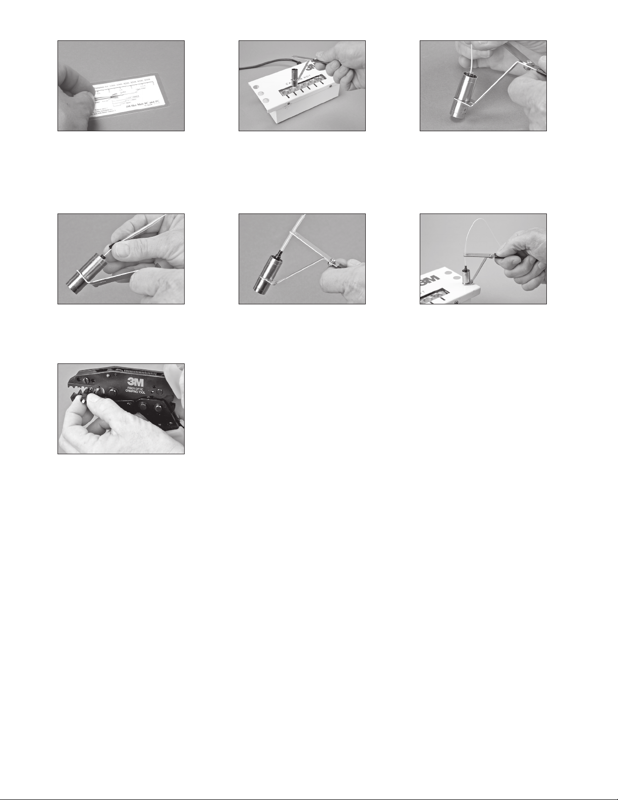
5.13 Check the final strip lengths and adjust if
necessary.
5.14 Remove the 3M™ Universal Connector
Holder from the 3M Hot Melt Oven by
grasping the cool-touch handle.
Caution: Do not touch the metal portion of the
holder or connector, as it will be hot!
5.15 Feed the fiber into the back of the 3M Hot
Melt Connector, until the buffer stops inside
the connector.
5.16 Slide the metal crimp ring assembly onto
the back of the connector.
5.19 Once connector has cooled, remove
from connector holder. Using the die
labeled.190, crimp the large portion of
thecrimp ring onto the connector.
Note: If installing the SC-FC 2.4 mm red
crimp ring, use the die labeled .120 to crimp
the jacket.
Proceed to Section 9: Scribing, Page 18.
5.17 Push the buffered fiber into the cable
retention feature until secure.
5.18 Rest the connector holder in one of the
available cooling ports located on both sides
of the oven. Let cool for three minutes.
11
Find Quality Products Online at: [email protected]
www.GlobalTestSupply.com
Page 12
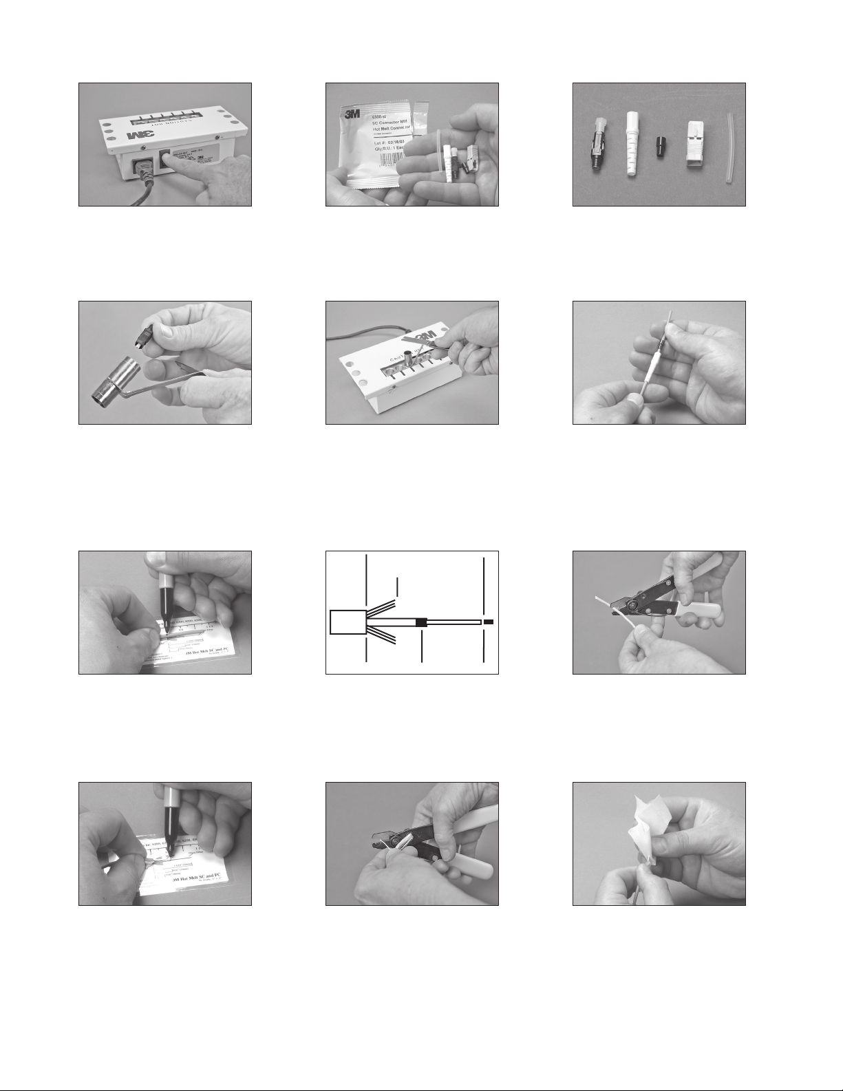
6.0 3M™ Hot Melt SC Connector 3 mm Jacketed Cable
1 3/16"
(30 mm)
5/16"
(8 mm)
9/16"
(14-16 mm)
9/16" Min.
(14 mm)
A B C D E
6.1 Plug in the 120V or 230V power cord.
Turn on the 3M
™
Hot Melt Oven. The oven
requires six minutes to warm up.
6.4 Load the SC Connector into the longer end
of the 3M
™
Universal Connector Holder.
6.2 Open the connector package and remove
components.
6.5 Place the connector holder into an available
port in the oven.
Note: The hot melt connector should be in
the oven for at least 60 seconds. The
connector should not be in the oven
longer than five minutes.
6.3 Each connector package contains a
connector (A), strain relief boot (B), metal
crimp ring (C), outer shell (D) and clear
strain relief tube (E).
6.6 Place the strain relief boot, then the metal
crimp ring on the jacketed fiber, as shown.
Note: SC-FC Crimp Rings for 2.4 mm jackets
are available separately.
6.7 Place the jacketed fiber on the strip
template for “SC Hot Melt” and use the
6.8 Strip Template 6.9 Using the 3M™ Stripping Tool 6362-TH
score the jacket and remove by hand.
fiber-marking pen to mark the location of
the jacket cut, approximately 1-3/16"
(30 mm) from the end.
6.10 Fold back the Kevlar® fibers and mark
where the buffer should be stripped.
Find Quality Products Online at: [email protected]
6.11 Using the 3M™ Stripping Tool 6362-TH,
6.12 Using a lint free cloth moistened with
remove the buffer in small pieces until
9/16" (14 mm) of buffer is protruding from
the end of the jacket.
12
www.GlobalTestSupply.com
Isopropyl alcohol, clean the bare fiber to
remove any oils or Acrylate coating debris.
Page 13
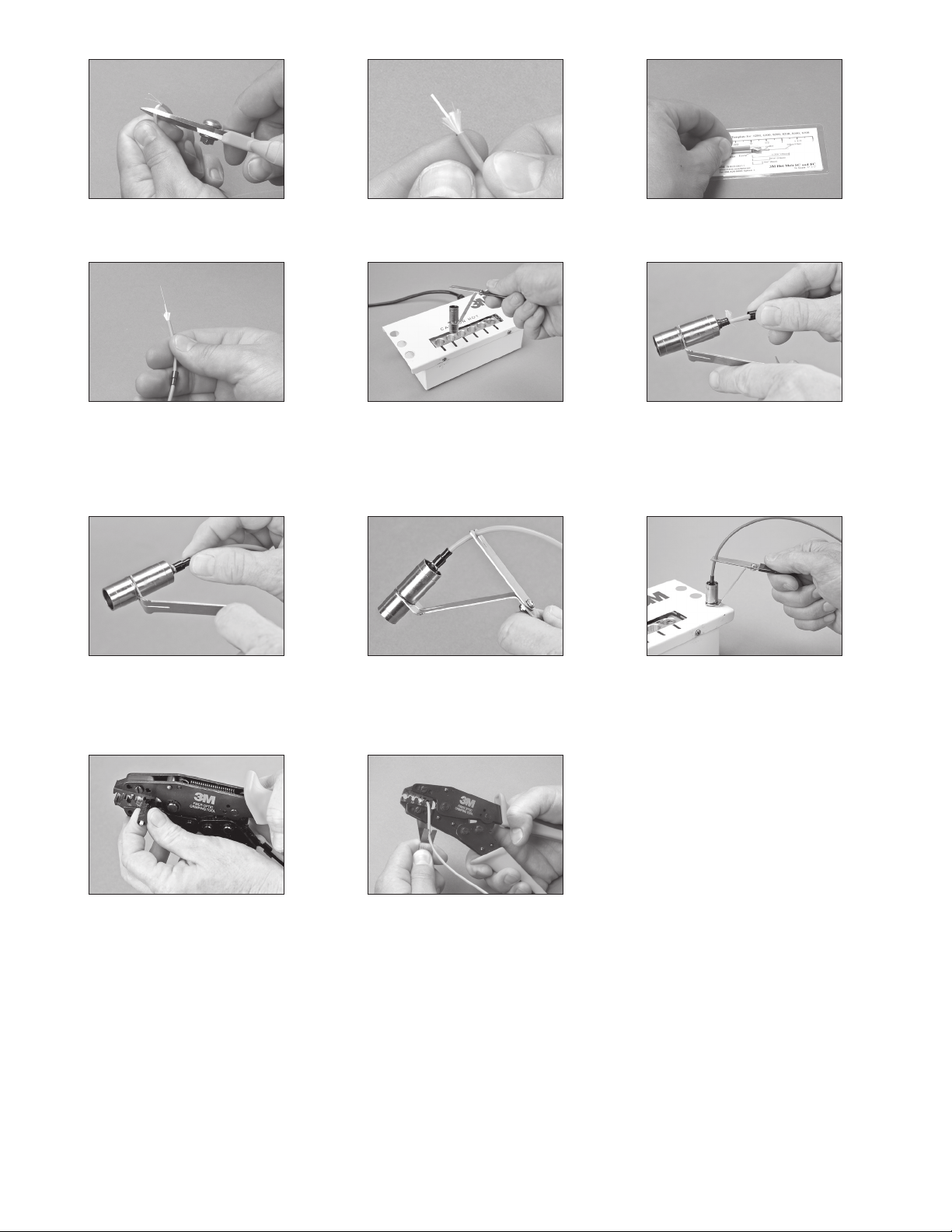
6.13 Gather the Kevlar® fibers to one side and
cut to length, approximately 5/16”.
6.14 Flare the Kevlar® fibers equally around the
buffered fiber.
6.15 Check the final strip lengths and adjust if
necessary.
6.16 Position the metal crimp ring towards the
end of the cable where it will be easily
accessible.
6.19 Slide the metal crimp ring onto the back of
the connector, capturing the Kevlar
®
fibers.
6.17 Remove the 3M™ Universal Connector
Holder from the Hot Melt Oven by grasping
the cool-touch handle.
Caution: Do not touch the metal portion of the
holder or connector, as it will be hot!
6.20 Push the jacketed fiber into the cable
retention feature until secure
6.18 Feed the fiber into the back of the 3M Hot
Melt Connector, pushing until the jacket
stops on the connector. Flare the Kevlar
®
fibers equally around the buffered fiber.
6.21 Rest the connector holder in one of the
available cooling ports located on both sides
of the oven. Let cool for three minutes.
6.22 Once connector has cooled, remove
from connector holder. Using the die
labeled.190, crimp the large portion of
thecrimp ring onto the connector.
6.23 Secure the small portion of the crimp ring
onto the jacket with the die labeled .137.
Note: If installing the SC-FC 2.4 mm red
crimp ring, use the die labeled .120 to crimp
the jacket.
Proceed to Section 9: Scribing, Page 18.
13
Find Quality Products Online at: [email protected]
www.GlobalTestSupply.com
Page 14
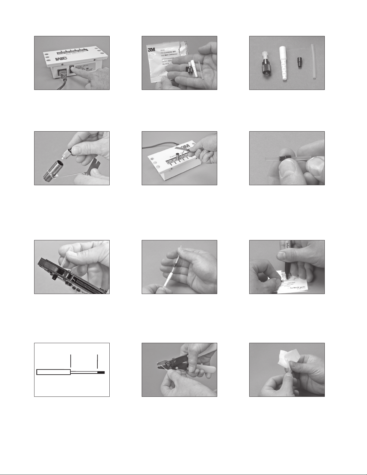
7.0 3M™ Hot Melt FC Connector 900 µm Buffered Fiber
A B C D
7.1 Plug in the 120V or 230V power cord.
Turn on the 3M
requires six minutes to warm up.
7.4 Load the FC Connector into the longer end
of the 3M
™
Hot Melt Oven. The oven
™
Universal Connector Holder.
7.2 Open the connector package and remove
components.
7.5 Place the connector holder into an available
port in the oven.
Note: The hot melt connector should be in
the oven for at least 60 seconds. The
connector should not be in the oven
longer than five minutes.
7.3 Each connector package contains a
connector (A), strain relief boot (B), metal
crimp ring (C) and clear strain relief
tube (D).
7.6 Insert the clear strain relief tube into
the metal crimp ring until the end of the
tube is positioned in the small half of the
crimpring.
7.7 Using the die labeled .137, crimp the small
half of the crimp ring to the clear strain
relief tubing.
9/16”
(14 mm)
7.10 Strip Template 7.11 Using the 3M™ Stripping Tool 6362-TH,
Find Quality Products Online at: [email protected]
7.8 Place the strain relief boot and clear strain
relief tube/crimp ring assembly on the
buffered fiber.
Note: SC-FC Crimp Rings for 2.4 mm jackets
are available separately.
remove the buffer in small pieces until
9/16” (14 mm) of buffer has been removed.
14
www.GlobalTestSupply.com
7.9 Place the buffered fiber on the strip
template for “FC Hot Melt” and use the fiber
marking pen to mark the location of the
buffer cut.
7.12 Using a lint free cloth moistened with
Isopropyl alcohol, clean the bare fiber to
remove any oils or Acrylate coating debris.
Page 15
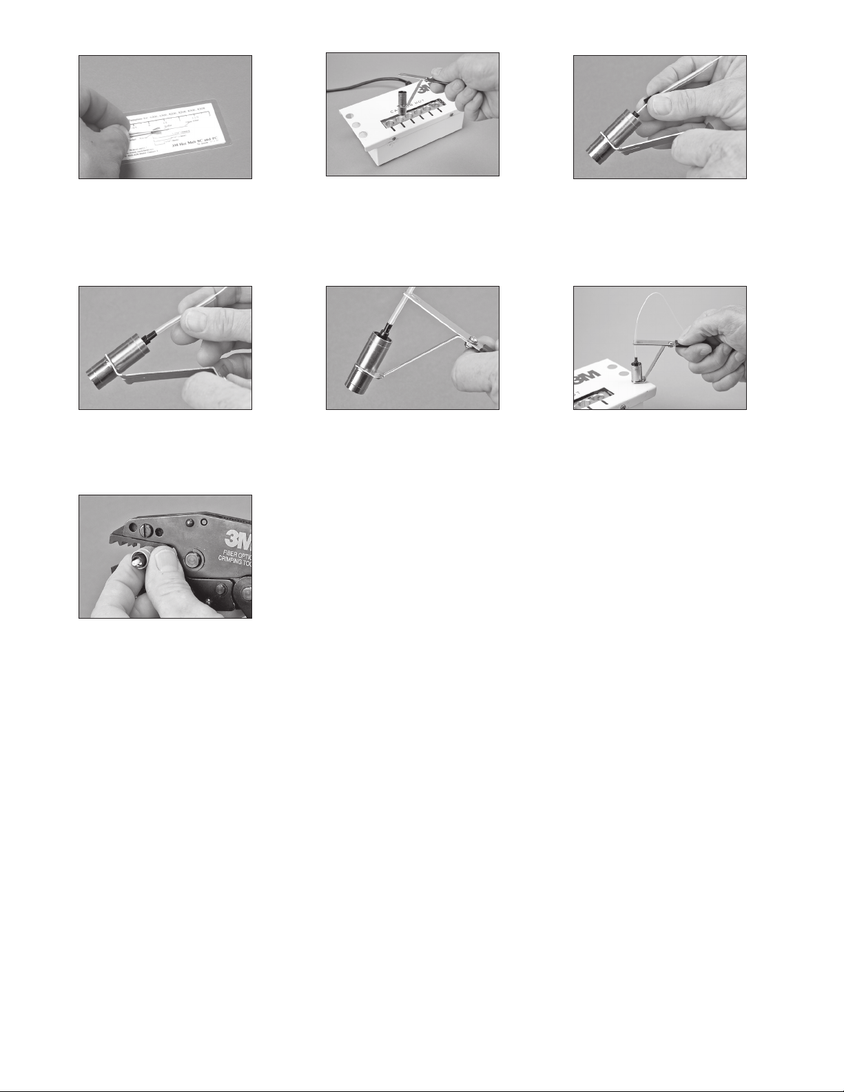
7.13 Check the final strip lengths and adjust if
necessary.
™
7.14 Remove the 3M
Holder from the Hot Melt Oven by grasping
the cool-touch handle.
Caution: Do not touch the metal portion of the
holder or connector, as it will be hot!
Universal Connector
7.15 Feed the fiber into the back of the 3M Hot
Melt Connector, until the buffer stops inside
the connector.
7.16 Slide the clear strain relief tube/crimping
assembly to the connector until it stops.
7.19 Once connector has cooled, remove
from connector holder. Using the die
labeled.190, crimp the large portion of
thecrimp ring onto the connector.
Note: If installing the SC-FC 2.4 mm red crimp
ring, use the die labeled .120 to secure
the crimp ring to the strain relief tube.
Proceed to Section 9: Scribing, Page 18.
7.17 Push the buffered fiber into the cable
retention feature until secure.
7.18 Rest the connector holder in one of the
available cooling ports located on both sides
of the oven. Let cool for three minutes.
15
Find Quality Products Online at: [email protected]
www.GlobalTestSupply.com
Page 16
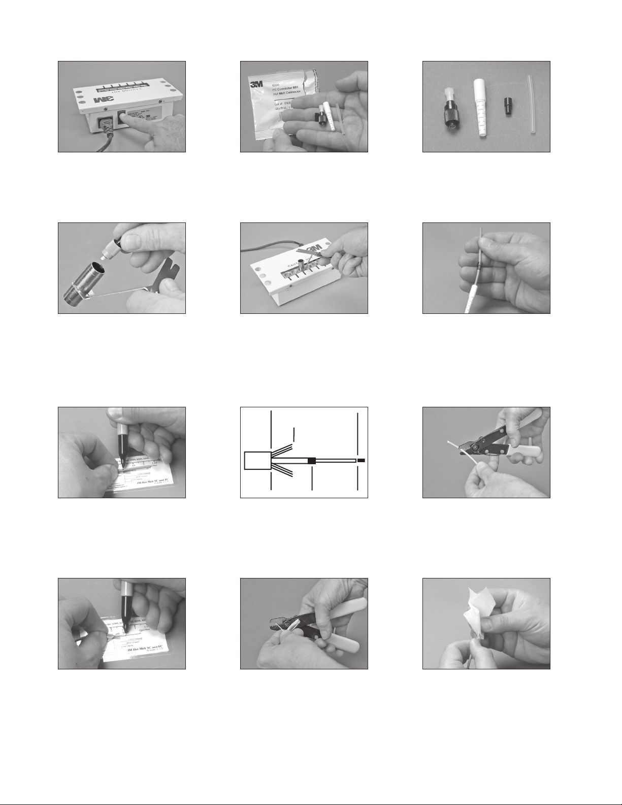
8.0 3M™ Hot Melt FC Connector 3 mm Jacketed Cable
1 3/16"
(30 mm)
5/16"
(8 mm)
9/16"
(14-16 mm)
9/16" Min.
(14 mm)
A B C D
8.1 Plug in the 120V or 230V power cord.
Turn on the 3M
™
Hot Melt Oven. The oven
requires six minutes to warm up.
8.4 Load the FC Connector into the longer end
of the 3M
™
Universal Connector Holder.
8.2 Open the connector package and remove
components.
8.5 Place the connector holder into an available
port in the oven.
Note: The hot melt connector should be in
the oven for at least 60 seconds. The
connector should not be in the oven
longer than five minutes.
8.3 Each connector package contains a
connector (A), strain relief boot (B), metal
crimp ring (C) and clear strain relief
tube (D).
8.6 Place the strain relief boot, then the metal
crimp ring on the jacketed fiber, as shown.
Note: SC-FC Crimp Rings for 2.4 mm jackets
are available separately.
8.7 Place the jacketed fiber on the strip
template for “FC Hot Melt” and use the
8.8 Strip Template 8.9 Using the 3M™ Stripping Tool 6362-TH,
score the jacket and remove by hand.
fiber-marking pen to mark the location of
the jacket cut, approximately 1-3/16" (30
mm) from the end.
8.10 Fold back the Kevlar® fibers and mark
where the buffer should be stripped.
Find Quality Products Online at: [email protected]
8.11 Using the 3M™ Stripping Tool, 6362-TH,
8.12 Using a lint free cloth moistened with
remove the buffer in small pieces until
9/16”” (14 mm) of buffer is protruding from
the end of the jacket.
16
www.GlobalTestSupply.com
Isopropyl alcohol, clean the bare fiber to
remove any oils or Acrylate coating debris.
Page 17
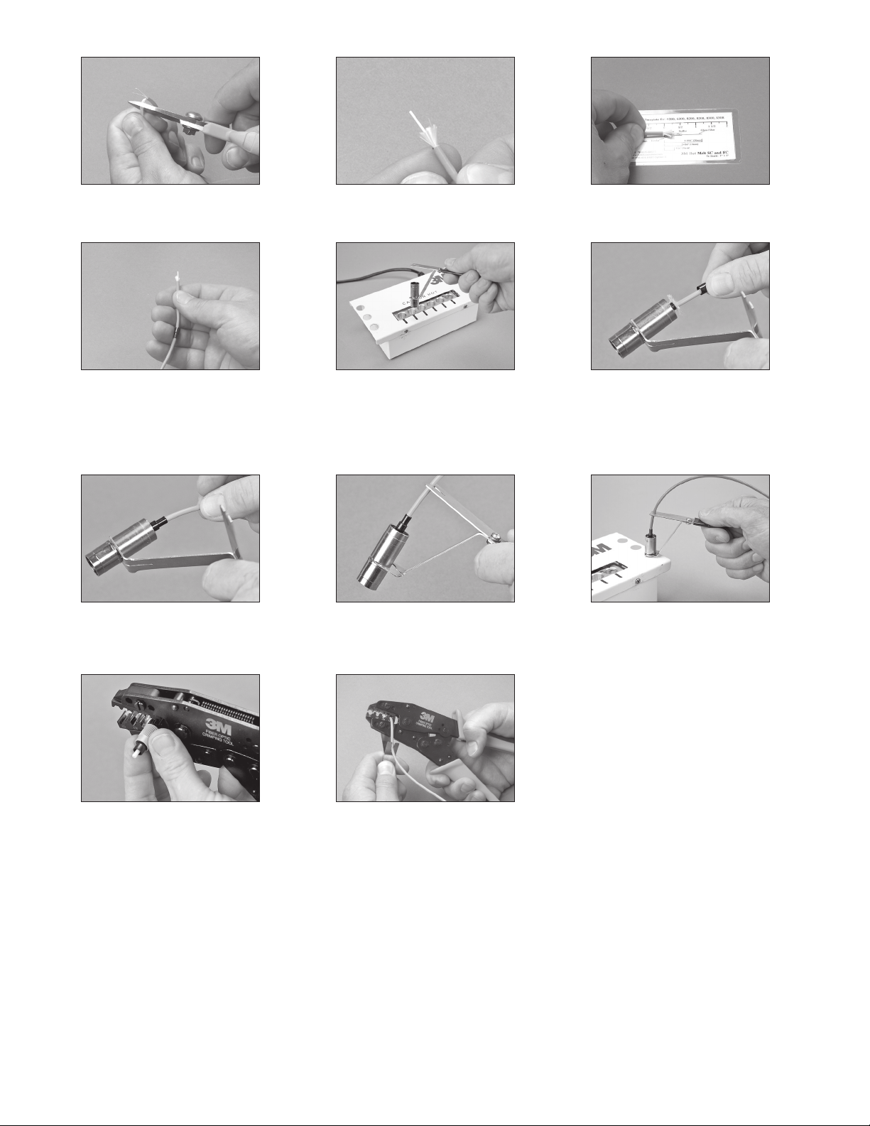
8.13 Gather the Kevlar® fibers to one side and
cut to length, approximately 5/16”.
8.14 Flare the Kevlar® fibers equally around the
buffered fiber.
8.15 Check the final strip lengths and adjust if
necessary.
8.16 Position the metal crimp ring towards the
end of the cable where it will be easily
accessible.
8.19 Slide the metal crimp ring onto the back of
the connector, capturing the Kevlar.
®
fibers
8.17 Remove the 3M™ Universal Connector
Holder from the 3M Hot Melt Oven by
grasping the cool-touch handle.
Caution: Do not touch the metal portion of the
holder or connector, as it will be hot!
8.20 Push the jacketed fiber into the cable
retention feature until secure.
8.18 Feed the fiber into the back of the 3M Hot
Melt Connector, pushing until the jacket
stops on the connector. Flare the Kevlar
®
fibers equally around the buffered fiber.
8.21 Rest the connector holder in one of the
available cooling ports located on both sides
of the oven. Let cool for three minutes.
8.22 Once connector has cooled, remove
from connector holder. Using the die
labeled.190, crimp the large portion of
thecrimp ring onto the connector.
8.23 Secure the small portion of the crimp ring
onto the jacket with the die labeled .137.
Note: If installing the SC-FC 2.4 mm red crimp
ring, use the die labeled .120 to crimp
the jacket.
Proceed to Section 9: Scribing, Page 18.
17
Find Quality Products Online at: [email protected]
www.GlobalTestSupply.com
Page 18
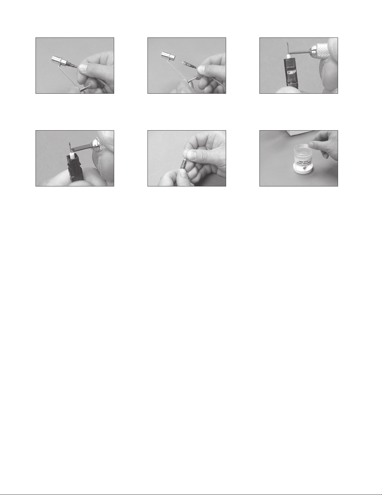
9.0 Scribing
9.1 Remove the 3M™ Hot Melt Connector from
9.4 Score the fiber by gently sliding the blade
Caution: The fiber should not break during
™
the 3M
Universal Connector Holder if
necessary.
across the fiber just above the bead of
adhesive. Scoring means that you are
making a small scratch on the outside of
the fiber.
thisstep.
9.2 Caution - Be careful so that you do not
break the protruding fiber.
9.5 Pull the fiber away from the connector. Pull
along the axis of the fiber, not to one side or
the other. If the fiber does not break away,
score the fiber again.
9.3 Position the scribe blade so the flat side of
the blade is resting on the bead of adhesive
and the blade is perpendicular to the fiber.
9.6 Dispose of the scrap fiber in the designated
container.
18
Find Quality Products Online at: [email protected]
www.GlobalTestSupply.com
Page 19
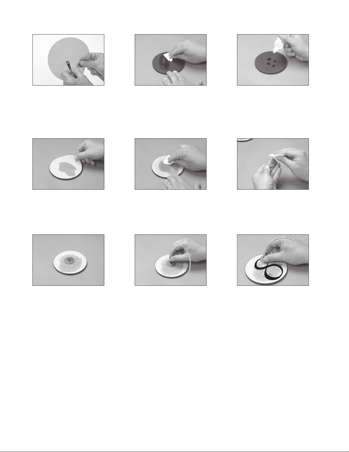
10.0 Multimode Polishing: Hot Melt
10.1 Perform an air polish by gently moving
Note: Each sheet of 9 micron lapping film
can be used for up to 20 connectors.
10.4 Before the alcohol evaporates, place a sheet
™
the 3M
Hot Melt Connector in a circular
motion on the gray, 9-micron 3M Lapping
Film, for approximately 10 rotations.
of the pale green, 2-micron 3M Lapping
Film, shiny side down on the pad. The
alcohol creates suction on the lapping film
and helps hold it in place.
10.2 Clean the round 3M Polishing Pad with a lint
free cloth moistened with Isopropyl alcohol.
10.5 Clean the lapping film with a lint free cloth
moistened with Isopropyl alcohol.
Note: The 2-micron lapping film can be used
for up to two connectors.
10.3 Place several drops of alcohol onto the
round rubber pad.
10.6 Clean the flat side of the 3M Polishing
Jig with a lint free cloth moistened with
Isopropyl alcohol.
10.7 Place the jig on the lapping film. 10.8 Place the ferrule in the jig until it stops. 10.9 Holding the connector and jig as shown,
19
Find Quality Products Online at: [email protected]
www.GlobalTestSupply.com
move the jig in a figure eight pattern with
light pressure. The speed of your figure
eights should be one to two per second.
After you have performed five figure eights,
increase to a medium pressure and polish
until all of the adhesive has been removed.
Then, polish an additional three figure
eights.
NOTE: The jig will feel much easier to push
immediately after the adhesive has been
removed.
Page 20
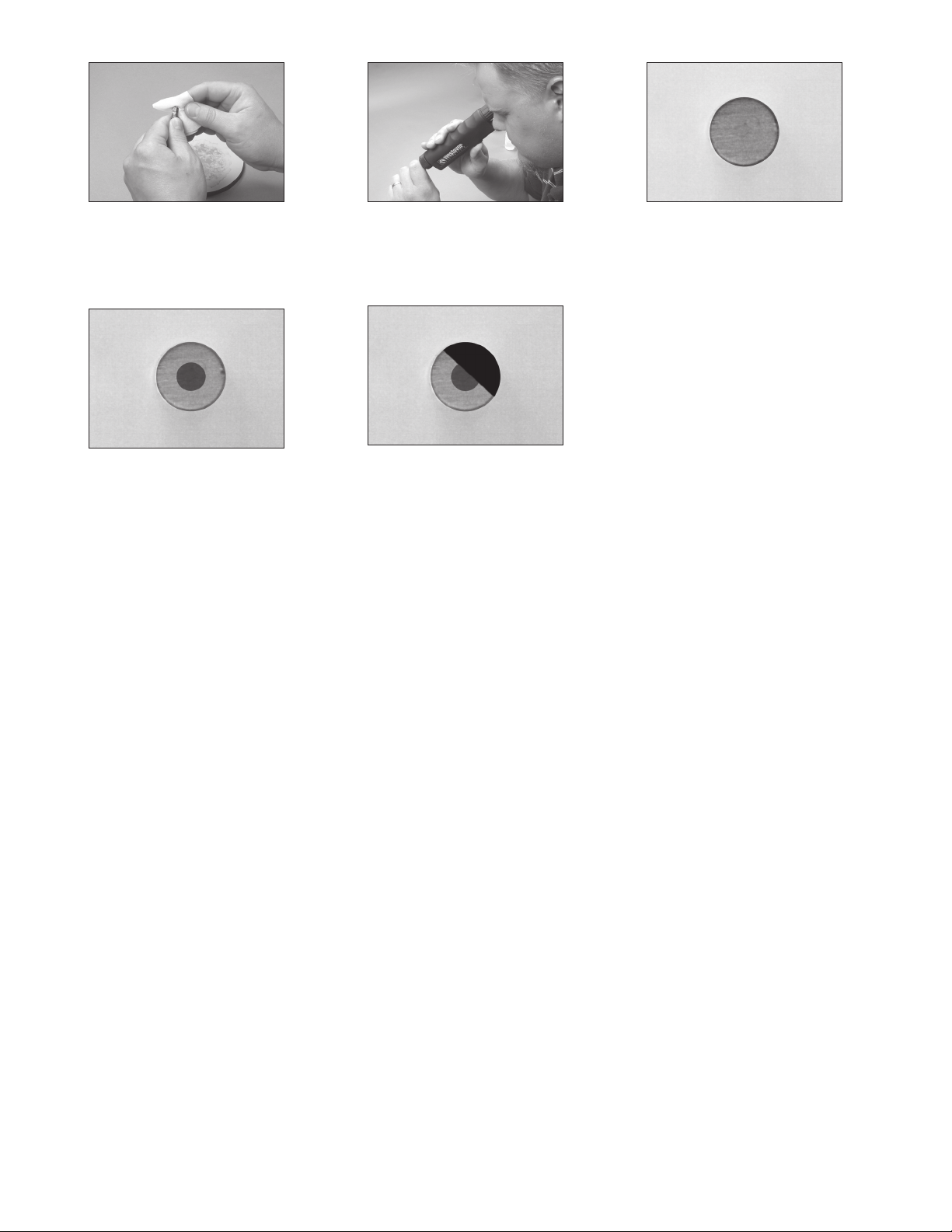
10.10 Clean the 3M™ Hot Melt Connector endface
with a lint free cloth moistened with
Isopropyl alcohol.
10.11 Inspect the connector endface with the
fiber through coaxial and oblique views by
changing the view with the thumbswitch on
the body of the 3M View Scope.
10.12 Good Polish (coaxial)
10.13 Good Polish (oblique)
10.14 Bad Polish - requires re-termination
20
Find Quality Products Online at: [email protected]
www.GlobalTestSupply.com
Page 21
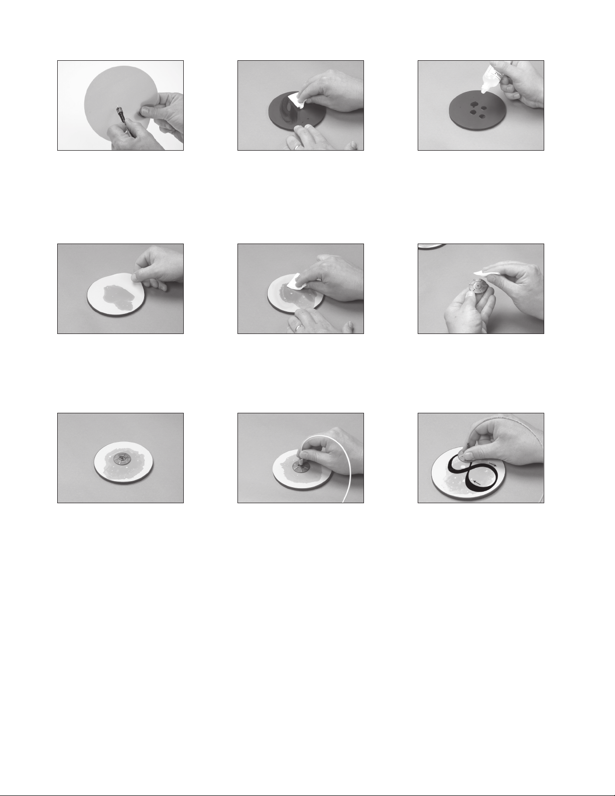
11.0 Singlemode Polishing: Hot Melt
11.1 Perform an air polish by gently moving the
connector in a circular motion on the gray,
9-micron lapping film, for approximately 10
rotations.
Note: Each sheet of 9 micron lapping film
can be used for up to 20 connectors.
11.4 Before the alcohol evaporates, place a sheet
of the pale green, 2-micron lapping film,
shiny side down on the pad. The alcohol
creates suction on the lapping film and
helps hold it in place.
11.2 Clean the round polishing pad with a lint
free cloth moistened with Isopropyl alcohol.
11.5 Clean the lapping film with a lint free cloth
moistened with Isopropyl alcohol.
Note: The 2-micron lapping film can be used
for up to two connectors.
11.3 Place several drops of alcohol onto the
round rubber pad.
11.6 Clean the flat side of the polishing jig with
a lint free cloth moistened with Isopropyl
alcohol.
11.7 Place the jig on the lapping film. 11.8 Place the ferrule in the jig until it stops. 11.9 Holding the connector and jig as shown,
21
Find Quality Products Online at: [email protected]
www.GlobalTestSupply.com
move the jig in a figure eight pattern with
light pressure. The speed of your figure
eights should be one to two per second.
After you have performed five figure eights,
increase to a medium pressure and polish
until all of the adhesive has been removed.
Then, polish one additional figure eight only.
NOTE: The jig will feel much easier to push
immediately after the adhesive has been
removed.
Page 22
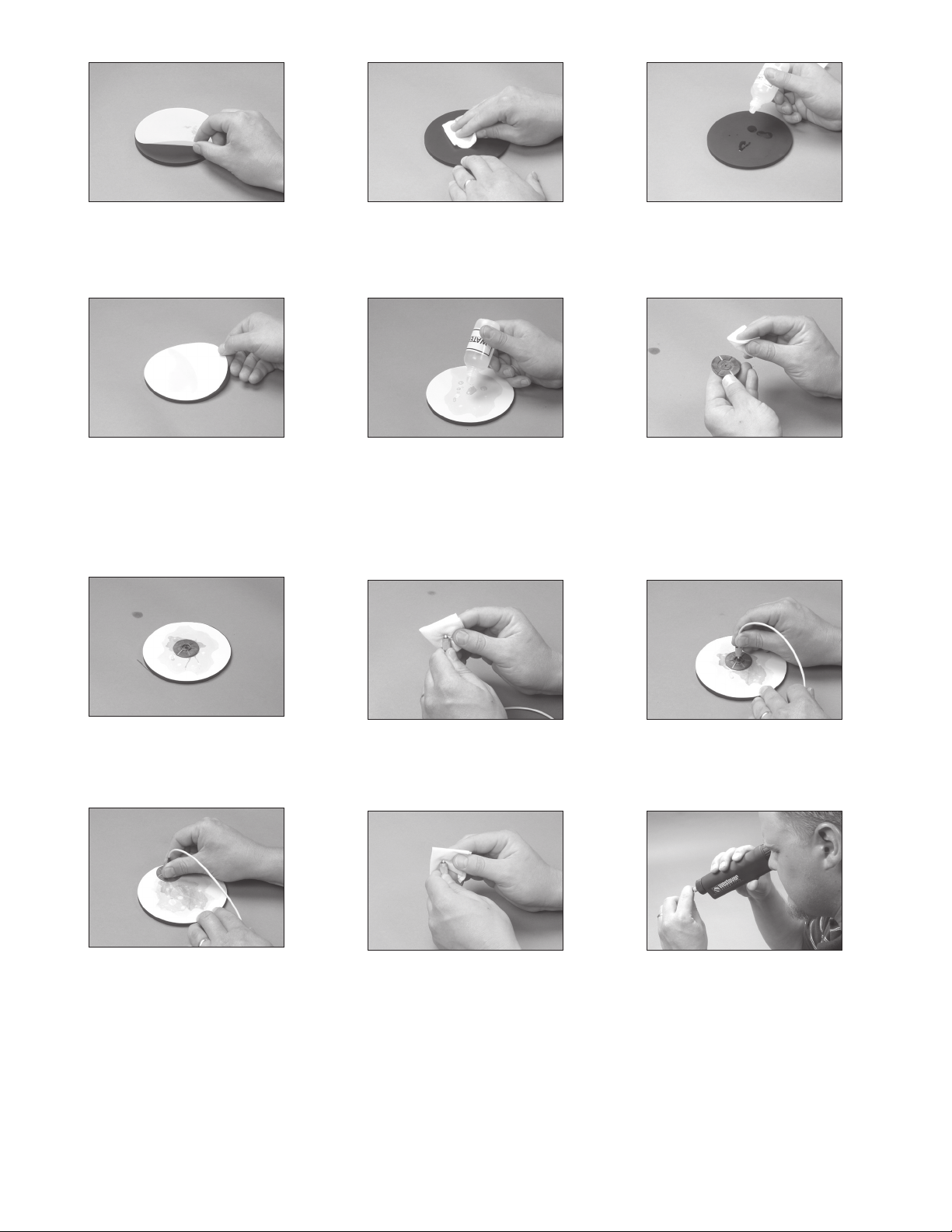
11.10 Remove the pale green, 2-micron 3M
Lapping Film from the round polishing pad.
11.11 Clean the round 3M Polishing Pad with a lint
free cloth moistened with Isopropyl alcohol.
11.12 Place several drops of alcohol onto the
round rubber pad.
11.13 Before the alcohol evaporates, place a sheet
of the frosted white final polish 3M Lapping
Film, shiny side down on the pad.
Note: Each sheet of frosted white final polish
lapping film can be used for up to five
connectors
11.16 Place the jig on the lapping film.
11.14 Final Polish: Clean the lapping film with a
lint free cloth and distilled water. Add several
drops of distilled water onto the lapping film.
Note: Do not use alcohol on the final polish
film as it will remove the grit on the film.
11.17 Clean the 3M Hot Melt Connector endface
with a lint free cloth moistened with
Isopropyl alcohol.
11.15 Clean the flat side of the 3M Polishing
Jig with a lint free cloth moistened with
Isopropyl alcohol.
11.18 Place the ferrule in the jig until it stops.
11.19 Polish the connector for four to eight figure
eights only.
Find Quality Products Online at: [email protected]
11.20 Clean the connector endface with a lint free
cloth moistened with Isopropyl alcohol.
22
11.21 Inspect the connector endface with the
www.GlobalTestSupply.com
fiber through coaxial and oblique views by
changing the view with the thumbswitch on
the body of the 3M View Scope.
Page 23
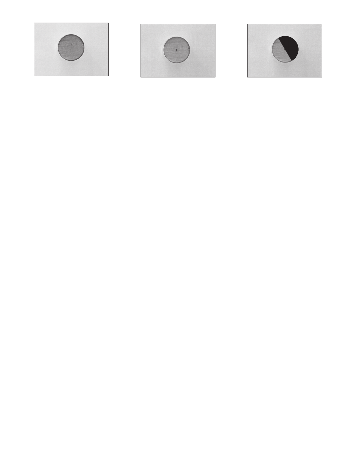
11.22 Good Polish (coaxial)
11.23 Good Polish (oblique) 11.24 Bad Polish - requires re-termination
23
Find Quality Products Online at: [email protected]
www.GlobalTestSupply.com
Page 24
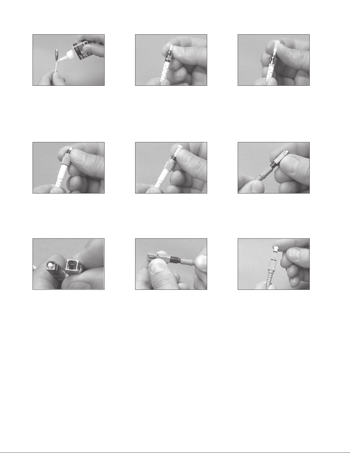
12.0 Finishing
12.1 Optional Step: For high stress situations,
you may wish to apply a small amount of
™
the 3M
Pronto™ Instant Adhesive, CA-8
around the cable directly past the crimp
ring, and at the end of the body of the ST
Connector. Immediately install the strain
relief boot.
12.4 3M™ Hot Melt FC Connector - Slide the
strain relief boot onto the back of the
connector.
12.2 3M
12.5 3M™ Hot Melt FC Connector - If the
™
Hot Melt ST Connector - Slide the
strain relief boot onto the back of the
connector.
connector is not to be immediately put into
service, install the protective dust cap.
12.3 3M™ Hot Melt ST Connector - If the
connector is not to be immediately put into
service, install the protective dust cap.
12.6 3M™ Hot Melt SC Connector - Slide the
strain relief boot onto the back of the
connector, ensuring the flat sides of the
boot are in line with the flat sides of the
connector.
12.7 3M™ Hot Melt SC Connector - Install the
outer shell of the connector by aligning the
profile of the connector’s outer shell, with
the connector body.
Find Quality Products Online at: [email protected]
12.8 3M™ Hot Melt SC Connector - Slide the
connector into the backside of the outer
shell. The shell will snap into place.
24
12.9 3M™ Hot Melt SC Connector - If the
www.GlobalTestSupply.com
connector is not to be immediately put into
service, install the protective dust cap.
Page 25

13.0 3M™ Field Termination Kit Replacement Part Numbers
3M™ Hot Melt Universal Termination Kit
Product Number Description Packaging
6366 Hot Melt Termination Kit 120 V 1 kit
6362 Hot Melt Termination Kit 230 V 1 kit
Replacements for 3M™ Hot Melt Universal Termination Kit
Product Number Description Packaging
6365-CC Hot Melt Consumable Kit
6365-CT Universal Crimp Tool 1 ea.
6365-HH Universal Connector Holder 4 ea.
6365-PP Polishing Pad, One Step 1 ea.
8892 Universal Polishing Jig 1 ea.
6365-FS Carbide Fiber Scribe 1 ea.
6365-VS 200x View Scope 1 ea.
6362-TH Tri-Hole Fiber Stripping Tool 1 ea.
6365-KS 3M
6366-CW Lints Free Cloths 100 shts
6312 Hot Melt Oven (6 port) 120 V 1
6323 Hot Melt Oven (6 port) 230 V 1
6851-E Autopolisher 1
SC-FC Crimp Ring 2.4 mm Red 60 ea.
254X 2-μm One Step Lapping Film
863X Final Polish Lapping Film
Lint Free Cloths
8892 Universal Polishing Jig
Pronto Adhesive
™
Aramid Yarn Snips 6365-KS 1 ea.
1 ea.
200 sheets
80 sheets
200 Sheets
1 ea.
1 ea.
25
Find Quality Products Online at: [email protected]
www.GlobalTestSupply.com
 Loading...