

Page 1

3443-94
Locator Plate Instructions
Instructions for the assembly of
3M .100" x .100" and .100" x .200"
socket connectors
General information
3M manual and pneumatic assembly presses and accessory
assembly equipment are recommended for the termination of
3M socket connectors. 3M assembly equipment is offered to
reduce set-up time, to provide easy and fast assembly, and to
reduce assembly error.
*The 3443-94 Locator Plate was designed to assemble all socket connectors, and replaces plates 3443-54, 3443-60, and 3443-73.
.100" x .200" Backplane System Chart
.100" x .100" Grid System Chart
-60 or -73
-60 or -73
-60 or -73
-60 or -73
-60 or -73
-94
-94
-94
-94
-94
-1A
-1A
-1A
-1A
-9A
12
12
12
12
12
12
1
⁄2
12 1⁄2
12 1⁄2
12 1⁄2
12 1⁄2
Self-adjusting
Self-adjusting
Self-adjusting
Self-adjusting
Self-adjusting
Contact
Quantity
3M Socket
Part No.
Locator*
Plate No.
3443
Locator
Plate No.
3443
Assembly
Platen
3442
Shut Height Adjustment for 3M Assembly Press
3316 &
3640
3335 3830
10
14
16
20
24
26
30
34
36
40
44
50
60
64
3473
3385
3452
3421
3626
3399
3419
3414
9436
3417
9444
3425
3334
7964
-54 or -73
-54 or -73
-54 or -73
-54 or -73
-54 or -73
-54 or -73
-54 or -73
-54 or -73
-54 or -73
-54 or -73
-54 or -73
-54 or -73
-54 or -73
-54 or -73
-94
-94
-94
-94
-94
-94
-94
-94
-94
-94
-94
-94
-94
-94
-1A
-1A
-1A
-1A
-1A
-1A
-1A
-1A
-1A
-9A
-9A
-9A
-9A
-9A
12
12
12
12
12
12
12
12
12
12
12
12
12
12
12
1
⁄2
12 1⁄2
12 1⁄2
12 1⁄2
12 1⁄2
12 1⁄2
12 1⁄2
12 1⁄2
12 1⁄2
12 1⁄2
12 1⁄2
12 1⁄2
12 1⁄2
12 1⁄2
Self-adjusting
Self-adjusting
Self-adjusting
Self-adjusting
Self-adjusting
Self-adjusting
Self-adjusting
Self-adjusting
Self-adjusting
Self-adjusting
Self-adjusting
Self-adjusting
Self-adjusting
Self-adjusting
20
26
34
40
50
3575
3501
3310
3318
3307
Contact
Quantity
3M Socket
Part No.
Locator*
Plate No.
3443
Locator
Plate No.
3443
Assembly
Platen
3442
Shut Height Adjustment for 3M Assembly Press
3316 &
3640
3335 3830
Page 2
viewing port points to the respective .1" x .1" or .l" x .2"
label guide.
Standard flat cable
To assemble standard flat cable, the cable width is guided
between:
•
The narrow end guide area
•
The side of the end guide with the viewing port feature
Ground plane cable
To assemble ground plane cable, the cable width is guided
between:
•
The wide end guide area
•
The side of the end guide that does not have the viewing
port feature
Center bump feature
The center bump connector does not require any special setup procedure.
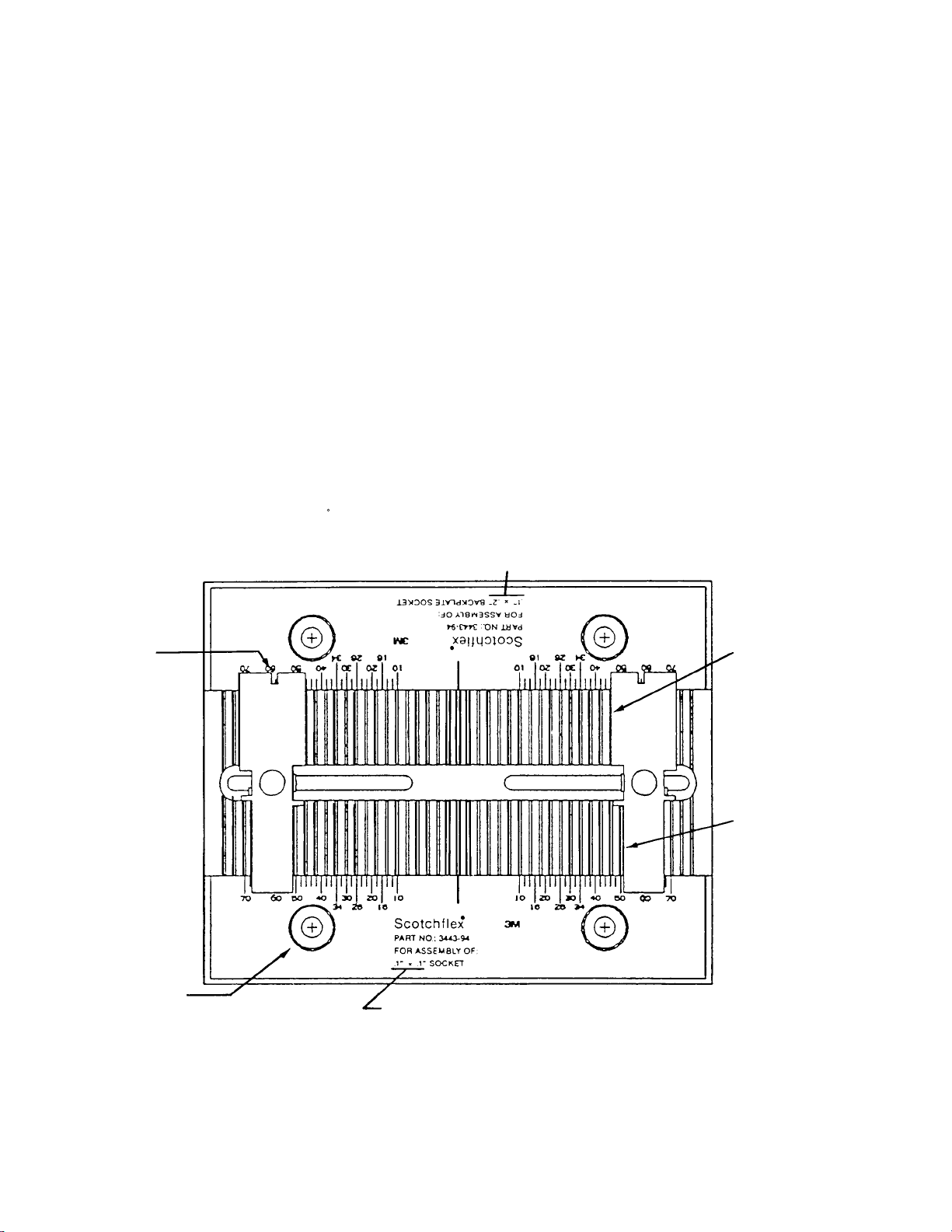
Adjustments to plate
Various adjustments are required to the locator plate,
depending on which socket connector or cable is being
assembled. Locator Plate 3443-94 is the recommended
assembly aid. (See Figure 1)
The 3443-94 Locator Plate can be used to assemble:
•
.1" x .1" and .1" x .2" socket connectors with and without
center bump feature
•
Socket connectors with standard flat cable and with ground
plane cable
End Guide set-up
To adjust the position of the end guide for the connector
length position, lift the end guide up and move it left or right.
The viewing port on each end guide must align with the
appropriate connector conductor size. The connector
conductor size is specified by the numbers on the respective
labels.
To adjust the end guide position for the .l" x .1" or .l" x .2"
connector, lift and rotate the end guide 180 so that the
Set-up procedures for sockets, cables and guides
Figure 1.
3443-94 Locator Plate
Locator Plate
Positioning Hole
.1” x .1” Side
Ground Plane
Cable
Locating Edge
End Guide
Standard
Cable
Locating
Edge
.1” x .2” Side
Viewing
Port
Page 3

Shut height adjustment procedures
The shut height setting is referenced in the .100" x .200"
Backplane System Chart and .100" x .100" Grid System
Chart on page l. Shut height settings are guidelines for proper
termination depth.
The shut height should be adjusted from the base before the
locator plate is put into place. The 3316 and 3640 are
adjusted with a knob at the top of the press. Press 3335 is
adjusted with the collar on the press shaft, and Press 3830 is
self-adjusting.
l. Place the shut height gauge, #3436-lA, across the base of
the assembly press. Lower the handle of the press until the
handle casting makes contact with the press casting.
(See Figure 2)
2. Determine the type of assembly press you are using:
• With the 3335 Press, lock the shut height adjustment
collar toward the base of the press shaft. (See Figure 3a)
• With the 3316 and 3640 Presses, turn the shut height
adjustment knob until the bottom of the press shaft
contacts the desired position on the shut height gauge.
(See Figure 3b).
3. Install the locator plate and appropriate platen on the press.
The platen should be positioned so that it is parallel with
the connector body and cover.
Figure 3b. 3316 & 3640 Press Assemblies
Figure 3a. 3335 Press Assembly
Figure 2.
Assembly Press
Casting
Press Shaft
Press Height Guage
Locking
Ring
Shut Height
Adjustment
Collar
CW (Lower)
CCW (Raise)
Shut Height
Adjustment Knob
Page 4

Figure 7.
Call 800-225-5373
for sales, ordering and technical product information
Connector/cable assembly procedures
1. Grasp a socket cover strip between thumb and
forefinger of both hands, with the liner facing you.
Rotate the outermost cover down against the adjacent
cover on the strip, breaking it from the liner. Pull
laterally away from the strip, leaving a clean adhesive
edge on the removed cover. (See Figure 4)
2. Firmly press ribbed side of cable into alignment grooves
on cover. The adhesive will help it stay in place. (See
Figure 5)
3. Visually inspect to insure that:
• Cable is properly aligned to cover grooves.
• Cable end is flush with cover for end terminations,
or perpendicular to cover for midspan terminations.
4. Place the cable/cover sub-assembly between the guides
on the locator plate, cover side down. (See Figure 6)
5. Orient and position connector body — contacts down
over the cable/cover sub-assembly, engaging cover
retainer devices with body slots. (See Figure 6)
6. Lower the assembly press handle fully to complete the
connection. (See Figure 7)
7. Raise press handle and remove completed assembly.
Visually inspect to insure that:
• Cover is fully seated and parallel with the body.
• Cable is properly aligned with the cover grooves.
• Cover retaining devices are completely engaged with
the body.
Figure 4.
Figure 5.
Figure 6.
All statements, technical information and recommendations related to
the Seller’s products are based on information believed to be reliable,
but the accuracy or completeness thereof is not guaranteed. Before
utilizing the product, the user should determine the suitability of the
product for its intended use. The user assumes all risks and liability
whatsoever in connection with such use.
Any statements or recommendations of the Seller which are not
contained in the Seller’s current publications shall have no force or
effect unless contained in an agreement signed by an authorized
officer of the Seller. The statements contained herein are made in lieu
of all warranties, express or implied, including but not limited to the
implied warranties of merchantability and fitness for a particular
purpose which warranties are hereby expressly disclaimed.
Seller shall not be liable to the user or any other person under any
legal theory, including but not limited to negligence or strict liability,
for any injury or for any direct or consequential damages sustained or
incurred by reason of the use of any of the seller’s products that were
defective.
Electronic Products Division
6801 River Place Blvd.
Austin, Texas 78726-9000
Printed on recycled paper.
Printed in the USA
© 3M 1993 34 7027 4814 5
Important Notice
 Loading...