

Page 1

Instructions and Parts List
™
3M-Matic
300cf
Case Former
Type 29800
For Use With 3M-Matic™:
100a Type 29600, 120a Type 19700,
120a3 Type 19700, 120ab Type 19700,
200a Type 39600, 700a Type 39600,
800a Type 39600, 800a3 Type 39600,
800ab Type 39600 Case Sealers
Important Safety
Information
Read "Important Safeguards",
pages 3 and 4, BEFORE
INSTALLING OR
OPERATING THIS
EQUIPMENT.
Note: The 300cf is not compatible with the Low
Tape Sensor Kit or outboard tape roll mounting
Serial No.
For reference, record machine serial number here.
3M Packaging Systems Division
3M Center, Building 220-8W-01
St. Paul, MN 55144-1000
"3M-Matic" is a Trademark of 3M,
St. Paul, MN 55144-1000
Printed in U.S.A.
© 3M 1999 44-0009-1974-4(A49.0)
Page 2

Replacement Parts and Service Information
To Our Customers:
This is the 3M-Matic™/AccuGlide™/Scotch™ brand equipment you
ordered. It has been set up and tested in the factory with "Scotch" brand
tapes. If technical assistance or replacement parts are needed, call or Fax
the appropriate number listed below.
T echnical Assistance
3M-Matic™ Helpline – 1-800/328 1390. Please provide the customer support
coordinator with the machine number, machine type/model and serial number.
If you have a technical question that does not require an immediate response,
you may Fax it to 715/381 0248.
Replacement Parts
Order parts by part number, part description and quantity required. Also
include machine name, number and type. A parts order form is provided at
the back of this manual.
3M/Tape Dispenser Parts
241 Venture Drive 1-800/344 9883
Amery, WI 54001-1325 FAX# 715/268 8153
Minimum billing on parts orders will be $25.00. Replacement part prices available on request.
$10.00 restocking charge per invoice on returned parts.
Note : Outside the U.S., contact the local 3M subsidiary for parts ordering information.
3M Packaging Systems Division
3M Center, Building 220-8W-01
St. Paul, MN 55144-1000
"3M-Matic", "AccuGlide" and “Scotch” are trademarks
of 3M, St. Paul, Minnesota 55144-1000
Printed in U.S.A.
© 3M 1997 44-0009-1851-4(D127.1)
Page 3

Replacement Parts And Service Information
To Our Customers:
This is the 3M-Matic™/AccuGlide™/Scotch™ brand equipment you
ordered. It has been set up and tested in the factory with "Scotch" brand
tapes. If any problems occur when operating this equipment, and you
desire a service call, or phone consultation, call, write or Fax the
appropriate number listed below.
SERVICE AND PARTS AVAILABLE DIRECT FROM:
Order parts by part number, part description and quantity required. Also include
machine name, number and type.
3M Packaging Systems Division
3M Center, Building 220-8W-01
St. Paul, MN 55144-1000
1-800/328 1390
"3M-Matic", "AccuGlide" and “Scotch” are trademarks
of 3M, St. Paul, Minnesota 55144-1000
Printed in U.S.A.
© 3M 1997 44-0009-1852-2(C127.1)
Page 4

Instruction Manual
300cf Case Former
Type 29800
Table of Contents Page
Intended Use..................................................................................................................................... 1
Equipment Warranty and Limited Remedy....................................................................................... 2
Contents............................................................................................................................................ 2
Important Safeguards ....................................................................................................................... 3 - 4
Specifications ............................................................................................................................. 5 - 6
Air Power Requirements .................................................................................. 5
Box Board......................................................................................................... 5
Box Weight and Size Capacities ...................................................................... 5
Operating Conditions........................................................................................ 5
Machine Dimensions ........................................................................................ 6
Installation and Set-Up ..................................................................................................................... 7 - 9
Receiving and Handling ................................................................................... 7
Machine Set-Up................................................................................................ 7 - 9
Operation .......................................................................................................................................... 11 - 14
Manual/Automatic Mode................................................................................... 12
Emergency Stop Button ................................................................................... 13
Reset Button..................................................................................................... 13
Box Centering Guides ...................................................................................... 13
Box Ejector ....................................................................................................... 13
Manual Operating Procedure ........................................................................... 13
Automatic Operating Procedure....................................................................... 14
Maintenance ..................................................................................................................................... 15
Cleaning of the Machine................................................................................... 15
Lubrication ........................................................................................................ 15
Pneumatic Diagram .......................................................................................................................... 16 - 17
Parts and Service Information .......................................................................................................... 19
Replacement Parts Illustrations and Parts List................................................................................. 21 - 37
i
Page 5
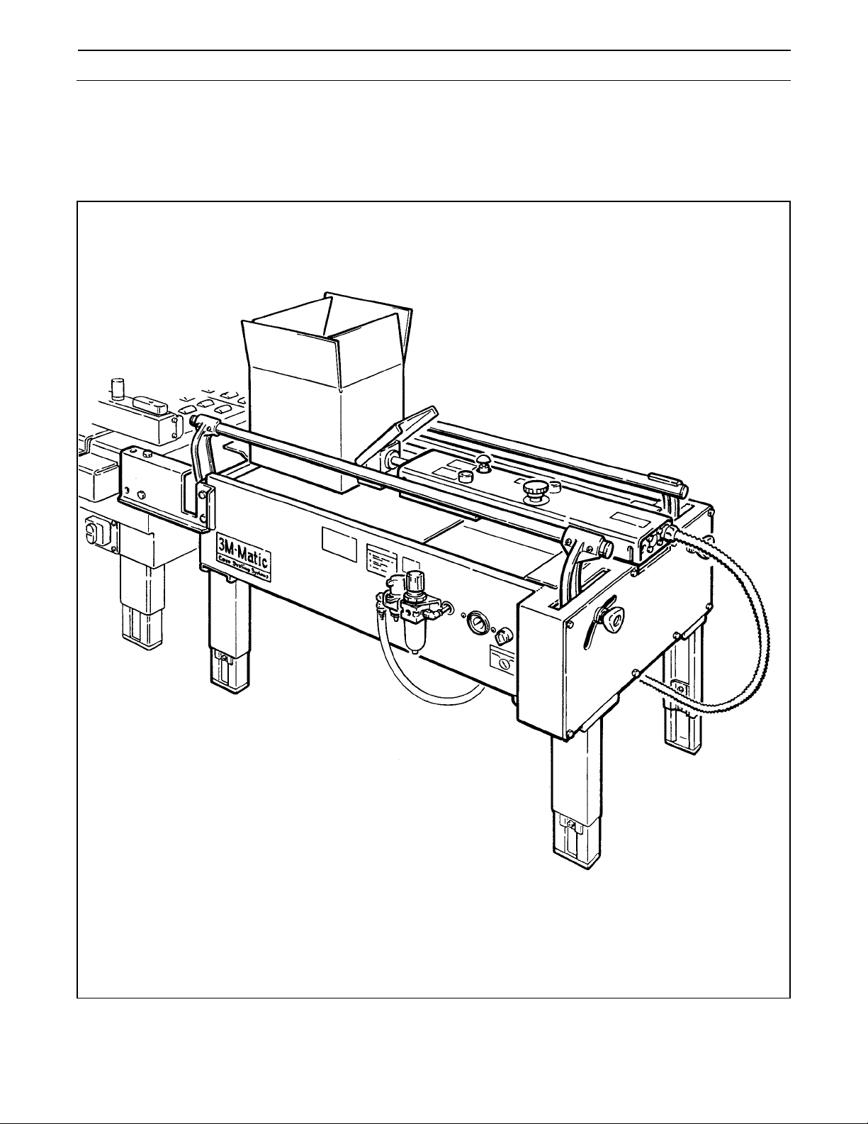
Intended Use
The 3M-MaticTM 300cf Case Former has been designed and tested for use with the following 3M-Matic™ case
sealers:
100a, 120a, 120a3, 120ab, 200a, 700a, 800a, 800a3 and 800ab. A regular slotted carton is placed on
the center rail of the case former and the bottom side flaps are automatically closed by the machine. A pneumatic
device pushes the carton into the case sealer for bottom sealing of the carton.
3M-MaticTM 300cf Case Former, Model 29800 (Shown installed with 800a Case Sealer).
1
Page 6

Equipment Warranty and Limited Remedy: THE FOLLOWING WARRANTY IS MADE IN LIEU OF ALL
OTHER WARRANTIES, EXPRESS OR IMPLIED, INCLUDING, BUT NOT LIMITED TO, THE IMPLIED
WARRANTY OF MERCHANTABILITY, THE IMPLIED WARRANTY OF FITNESS FOR A PARTICULAR
PURPOSE AND ANY IMPLIED WARRANTY ARISING OUT OF A COURSE OF DEALING, A CUSTOM OR
USAGE OF TRADE:
3M warrants that its 3M-Matic™ 300cf Case Former, Type 29800 will be free from defects for ninety (90) days
after delivery. If any part is proved to be defective within the warranty period, then the exclusive remedy and
3M’s and seller’s sole obligation shall be, at 3M’s option, to repair or replace the part, provided the defective part
is returned immediately to 3M’s factory or an authorized service station designated by 3M. A part will be
presumed to have become defective after the warranty period unless the part is received or 3M is notified of the
problem no later than five (5) calendar days after the warranty period. If 3M is unable to repair or replace the part
within a reasonable time, then 3M, at its option, will replace the equipment or refund the purchase price. 3M shall
have no obligation to provide or pay for the labor required to install the repaired or replacement part. 3M shall
have no obligation to repair or replace (1) those parts failing due to operator misuse, carelessness, or due to any
accidental cause other than equipment failure, or (2) parts failing due to non-lubrication, inadequate cleaning,
improper operating environment, improper utilities or operator error.
Limitation of Liability: 3M and seller shall not be liable for direct, indirect, special, incidental or consequential
damages based upon breach of warranty, breach of contract, negligence, strict liability or any other legal theory.
The foregoing Equipment Warranty and Limited Remedy and Limitation of Liability may be changed only by a
written agreement signed by authorized officers of 3M and seller.
Contents – 300cf Case Former
(1) 300cf Case Former, Type 29800
(1) Tool/Spare Parts Kit, P/N 78-8111-1356-8
(1) Instruction and Parts Manual
"3M-Matic" is a trademark of 3M, St. Paul, MN 55144-1000
2
Page 7
Important Safeguards
This safety alert symbol identifies
important safety messages in this
manual. READ AND UNDERSTAND THEM
BEFORE INSTALLING OR OPERATING
THIS EQUIPMENT.
Important – In the event the following safety
labels are damaged or destroyed, they must
be replaced to ensure operator safety. A
label kit, part number 78-8119-6942-3 is
available as a stock item or individual labels
can be ordered. See Parts Illustration/List,
pages 36 and 37.
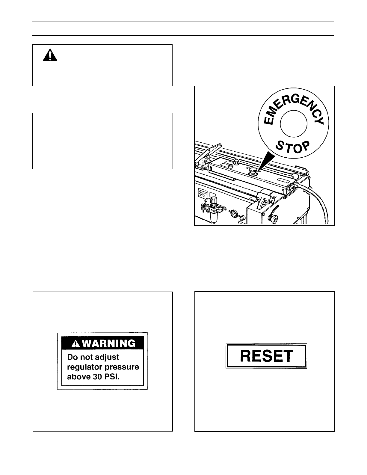
The "Emergency Stop" label, shown in Figure 1-2,
is attached to the top of the adjustable carton ejector
assembly around the E-Stop push-button. The label
reminds operators and casual personnel of the
function of this switch.
The "Warning – Air Pressure" label, shown in
Figure 1-1, is attached next to the return stroke air
pressure regulator. The regulator is located behind
the pneumatic compartment cover and is factory
adjusted. No operator adjustment is required.
Figure 1-2 – Emergency Stop Label
The "Re-Set" label, shown in Figure 1-3, is
attached to the top of the adjustable carton ejector
next to the "Reset"push-button. The "Reset" pushbutton must be pushed to restore air supply after
stopping machine with E-Stop switch.
Figure 1-1 – Air Pressure Warning Label
Figure 1-3 – Reset Label
3
Page 8
Important Safeguards (Continued)
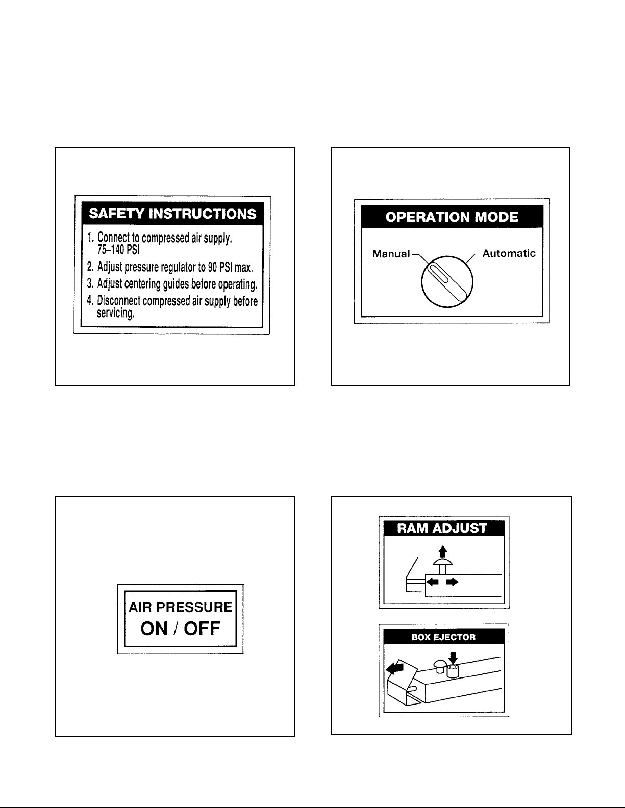
The "Safety Instructions label, shown in
Figure 1-4, is attached on the left side of the
machine frame. The label provides convenient
safeguard instructions for the operator and service
personnel.
The "Operation Mode" label, shown in Figure 1-6 is
attached on the left side of the machine frame below
the Manual/Automatic switch. The label indicates
the correct position of the switch for manual or
automatic operation.
Figure 1-4 – Safety Instructions Label
The "Air Pressure – On/Off" label, shown in
Figure 1-5, is attached on the left side of the
machine frame above the On/Off valve. The label
reminds operators of the location of the pneumatic
On/Off valve,
Figure 1-46– Operation Mode Label
The "Ram Adjust" and "Box Ejector" labels,
shown in Figure 1-7 are attached to the top of the
adjustable carton ejector. The labels remind
operators of the function of the push-button switch
and the adjustment detent knob.
Figure 1-5 – Air On/Off Label
Figure 1-7 – Ram Adjust and Box Ejector Labels
4
Page 9

Specifications
Air Power Requirements
517 kPa minimum gauge pressure, 6.0 m3/h @ 21°C, 101 kPa maximum at maximum cycle rate [75 PSIG
minimum gauge pressure, 3.5 SCFM maximum at maximum random cycle rate]. A pressure regulator-filter is
included. For best operation set pressure regulator to 90 PSIG.
Box Board
125 to 275 P.S.I. bursting test, single wall B, or C flute.
Boxes should be well scored for proper performance.
Box Weight and Size Capacities
A. Box weight, filled – 2.3 kg [5 lbs] minimum to 37 kg [80 lbs] maximum.
B . Sizes: Minimum Maximum
Length 205 mm [8.0 inch] 600 mm [23.5 inch]
Width 205 mm [8.0 inch] 545 mm [21.5 inch]
Height 100 mm [4.0 inch] limited by case sealer
Note: The box size capacities for the 300cf may be limited by the capacity of the case sealer in some
instances.
Operating Conditions
Use in dry, relatively clean environments at 5° to 40° C [40° to 105° F] with clean dry boxes.
IMPORTANT SAFEGUARD
Note –Machine should not be washed down or subjected to conditions causing moisture condensation on
components.
IMPORTANT SAFEGUARD
(Specifications continued on next page.)
5
Page 10
Specifications (Continued)
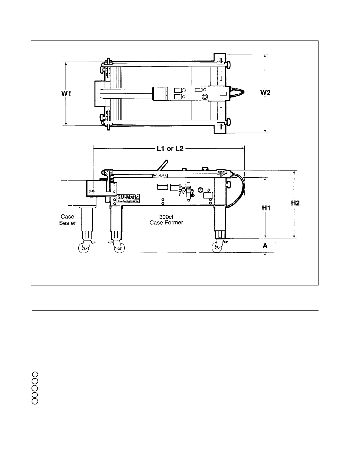
Machine Dimensions
1
A
H1
2
H2
2
L1
3,5
L2
4,5
W1 W2
Minimum
mm 120 610 685 1375 1385 615 765
[Inches] [4.81] [24.0] [27.0] [54.1] [54.6] [24.3] [30.2]
Maximum
mm 120 775 850 1705 1715 615 765
[Inches] [4.81] [30.5] [33.5] [67.1] [67.6] [24.3] [30.2]
1 Casters are optional
2 Includes the height of a plastic foot which is removed if casters are used.
3 L1 is 300cf Case Former connected to 120a, 120a3
4 L2 is 300cf Case Former connected to 100a, 200a, 700a, 800a, 800a3
5 Add 30 mm to these dimensions when connecting to a 120ab or 800ab
Weight – Approximate 86 kg [190 pounds] crated (approximate)
Approximate 75 kg [165 pounds] uncrated (approximate)
6
Page 11
Installation and Set-Up
Receiving And Handling
After the machine has been uncrated, examine the
case former for damage that might have occurred
during transit. If damage is evident, file a damage
claim immediately with the transportation company
and also notify your 3M Representative.
Machine Set-Up
Important – Read "Warnings", on page 12,
before attempting to set up the case former
for operation.
For future reference, record machine serial number
on front cover of this manual in the space provided.
The following instructions are presented in the order
recommended for setting up and installing the
case former, as well as for learning the operating
functions and adjustments. Following them step by
step will result in your understanding of the machine
and an installation in your production line that best
utilizes the many features built into the case former.
Refer to Figure 3-1 to identify the various
components of the case former.
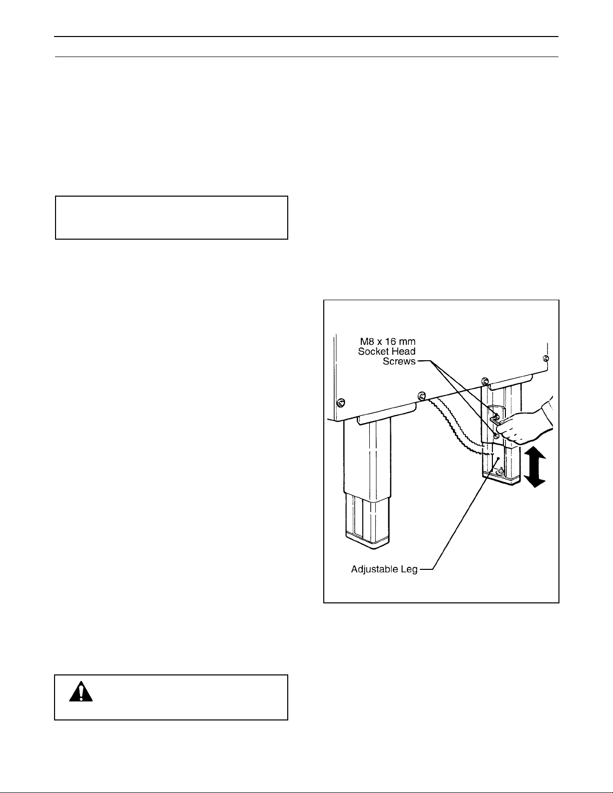
2. Adjust machine bed height.
The case former is equipped with four adjustable
legs that are located at the corners of the frame.
The legs can be adjusted to obtain different
conveyor bed heights from 610 mm [24.0 inch]
minimum to 775 mm [30.5 inch] maximum.
Refer to Figure 2-1 and adjust the bed height as
follows:
(a) Block up the machine frame to allow
adequate leg adjustment.
(b) Loosen, but do not remove, two M8 x 16
mm socket screws in one leg. Adjust
the leg length for the desired bed height.
Retighten the two screws to secure the
leg. Adjust all four legs equally.
Note – A tool kit consisting of metric open end
and hex socket wrenches is provided with the
machine. These tools should be adequate to set
up the machine, however, other tools supplied by
the customer will be required for machine
maintenance.
1. Follow "Unpacking Instructions" label attached
to corrugated packing cover.
Use appropriate material handling equipment to
remove the machine from the pallet and move it
into position.
Whenever the machine is lifted with a fork truck,
insure that the forks span completely across the
machine frame and do not contact any
mechanism under the machine frame.
CAUTION – Machine weighs
approximately 85 kg ]190 lbs]
uncrated.
Figure 2-1 – Bed Height Adjustment
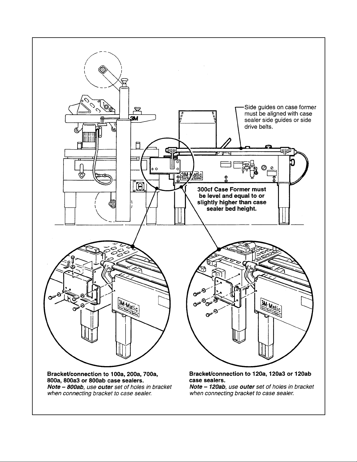
3. Install case former in production line.
Refer to Figure 2-2 for installation set up. Case
former bed must be level and equal or slightly
higher than case sealer bed height.
Install mounting brackets as shown in
Figure 2-2.
7
Page 12
Installation and Set-Up (Continued)
Figure 2-2 – Mounting Bracket Installation
8
Page 13
Installation and Set-Up (Continued)
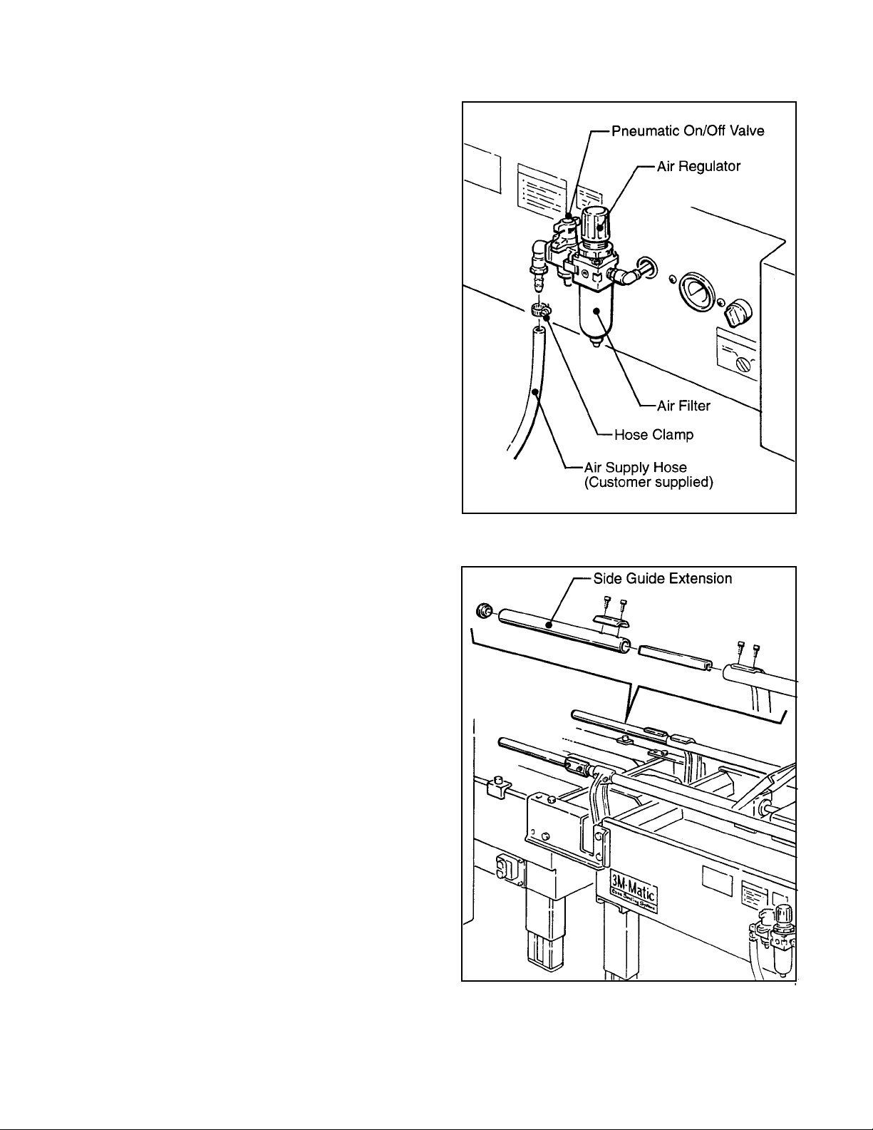
4. Pneumatic Connection
The case former requires a 5.2 bar gauge
pressure [75 PSIG], 6.0 m3/h @ 21°C, 1.01 bar
[3.5 SCFM] compressed air supply.
The customer supplied air supply hose should
be connected to the barbed fitting on the On/Off
valve and clamped tightly with the hose clamp
provided. See Figure 2-3. Shut the air valve off
and connect the air line. Turn the On/Off valve
On (SUP), to energize the pneumatic
components.
If another type of connector is desired, the
barbed fitting and/or elbow can be removed and
replaced with the desired connector. The air
On/Off valve inlet is 1/4-18 standard pipe
threads.
5. Side Guide Extensions
Under certain circumstances, the centering
guides may interfere with the side guides on the
100a, 200a or 700a case sealers. If this occurs,
the case sealer side guides can be removed and
centering guide extensions can be installed on
the 300cf Case Former. The side guide
extensions are included with the 300cf. Install
guides as shown in Figure 2-4.
6. After completing the "Installation and Set-Up"
procedure, continue through "Operation" to be
sure case former is properly set-up to run boxes.
Figure 2-3 – Pneumatic Connections
Figure 2-4 – Side Guide Extensions
9
Page 14

THIS PAGE IS BLANK
10
Page 15

Operation
IMPORTANT – Before operating the case former, read the "Important Safeguards", pages 3-4 and
"Warnings" on page 12 as well as all of the "Operation" instructions.
Refer to Figure 3-1 to acquaint yourself with the various components and controls of the case former.
Figure 3-1 – 300cf Case Former Components
11
Page 16

Operation (Continued)
WARNINGS
1. Turn air supply off before performing any adjustments or maintenance on the machine.
2. Turn air supply off when machine is not in use.
3. The case former contains flap folders and sliding components that operate in rapid succession. Keep hands out of this area when machine is in operation.
4. Failure to comply with these warnings could result in severe personal injury and/or equipment damage.
Manual/Automatic Mode
The operator can control the box movement from the
case former to the case sealer by the manual/
automatic mode switch located on the left side of the
frame. Figure 3-1.
In the manual mode, (for top and bottom taping) the
operator must press the ejector button (Figure 3-2)
to cause the ejector to move the box forward into the
case sealer.
In the automatic mode, (for bottom taping only) the
box is moved forward by the ejector without operator
assistance.
Figure 3-2 – Adjustable Carton Ejector
12
Page 17

Operation (Continued)
Emergency Stop Button
The E-Stop button can be pushed at any time to
stop machine operation and bleed air from the
pneumatic system.
Reset Button
When case former is stopped with E-Stop, the Reset
Button must be pushed to restore air supply to the
machine.
Box Centering Guide
The four knobs for locking the centering guides in
position are located at the front and rear of the
machine. Center the box in the machine with the
centering guides and tighten the knobs to lock
guides in place.
Box Ejector
The ejector and air cylinder are located on the top
center rail of the case former as shown in Figure 3-2.
The ejector is adjustable along the rail in 25 mm
[1 inch] increments to accommodate box lengths
from 205 mm [8 inch] minimum to 600 [23-1/2 inch]
maximum.
Manual Operating Procedure
(Top and Bottom Taping)
Refer to Figures 3-2 and 3-3
1. Turn case former air valve "On" (SUP).
2. Turn Manual/Auto valve to "Man".
3. Hold the empty box over the center rail. Fold
the front bottom flap on the rail and rear bottom
flap on the carton ejector.
4. Move box forward (toward case sealer) until
both side bottom flaps contact the bottom flap
actuator plates. The two bed plates will then
rotate up and fold the side box flaps up.
Figure 3-3 – Box Placement
5. Fill the box with product.
6. Close box top flaps, front and rear and then side
flaps.
7. While holding top flaps down, press "Eject"
button to move box into case sealer. Hold top
flaps down until box moves into case sealer.
The ejector will return to the rest position and
the bed plates will return to full open position
ready for the next box.
13
Page 18

Operation (Continued)
Automatic Operating Procedure
(Bottom Taping Only)
1. Raise case sealer upper taping head to
maximum height (if applicable).
2. Turn case former air valve "On" (SUP).
3. Turn Manual/Auto valve to "Auto".
4. Place open box with front and back bottom flaps
folded in, onto the case former center rail.
5. Move box forward (toward case sealer) until
both side bottom flaps contact the bottom flap
actuator plates. The two bed plates will then
rotate up and fold the side box flaps up.
The box ejector will automatically push the box
into the case sealer and then return to the rest
position ready for the next box.
14
Page 19

Maintenance
WARNING – Disconnect air
supply to the machine before
beginning any maintenance, Failure to
do so could result in personnel injury
or damage to the machine.
Cleaning of the Machine
Regular slotted containers produce a great deal of
dust and paper chips when processed or handled in
equipment. If this dust is allowed to build-up on
machine components, it can cause component wear.
The dust build-up can best be removed from the
machine by a shop vacuum. Depending on the
number and type of boxes used in the case former,
this cleaning should be done approximately once per
month. If the boxes are dirty, or if the environment in
which the machine operates is dusty, cleaning on a
more frequent basis may be necessary. Excessive
dirt build-up that cannot be removed by vacuuming
should be wiped off with a damp cloth.
Note – Never attempt to remove dirt from
machine by blowing it off with compressed air.
This can cause dirt to be blown into critical
machine components and cause premature wear.
Never wash down or subject machine to
conditions causing moisture condensation as
serious equipment damage could result.
Lubrication
The Lubrication Chart shown in Figure 4-1 illustrates
the frame points which should be lubricated every
250 hours of operation. Lubricate the rotating and
pivoting points noted by the arrows with SAE #30
non-detergent oil.
Note – Wipe off excess oil and grease. It will
attract dust which can cause premature equipment wear and jamming.
Description (Parts Drawing Reference/Item Number) Lubricant Instructions
Chain (Ref. No. 5422-9 & 5422-10) 2 Lightly coat chain
Sliding Block – Ejector Guide (Ref. No. 5424-13) 1 Lightly coat guide slots
Sliding Block – L/H (Ref. No. 5424-14) 1 Lightly coat guide slots
Sliding – Flap Folder (Ref. No. 5424-27) 1 Lightly coat guide slots
Lubricant 1. White Moly Grease With Liquilon, Plate Master #177L
2. NLGI Grade 2 Multi-purpose Film Forming With Liquilon, Polymere #400
Figure 4-1 – Lubrication Chart
15
Page 20

Pneumatic Diagram
On/Off Valve: SMC EVHS2500
Filter-Regulator: SMC EAW2000
Shuttle Valves: SMC EVZA5220
Roller Valves: Telemecanique PXC-M52
Flow Controls 1 and 2: Legris 7665-56-11
Pressure Regulator 2: SMC EAR111
Manual-Auto Select Valve: Telemecanique PXB-B1011BA2
Flow Control Valves
3 and 4: Legris 7665-56-14
Sensor Valves: Legris PWS-P
Bottom Side Flap
Cylinders: SMC C65B32-125C-Y2-*
Ejector Cylinder: SMC C65B40-500C-Y37-*
OR Valve: Telemecanique PLK-A11
Box Ejector Valve: Telemecanique PXB-B191
Figure 5-1 – Pneumatic Diagram
16
Page 21

17
Page 22

THIS PAGE IS BLANK
18
Page 23

Parts and Service Information
Labels
In the event that any labels are damaged or destroyed, they must be replaced to ensure operator safety. A
label kit, part number 78-8119-6942-3 is available as a stock item. It contains all the safety labels used on the
300cf Case Former or separate labels can be ordered from the parts list, page 37.
Replacement Parts Ordering Information and Service
Refer to the first page of this instruction manual "Replacement Parts and Service Information".
19
Page 24

THIS PAGE IS BLANK
20
Page 25

Replacement Parts Illustrations and Parts List
300cf Case Former, Type 29800
Frame Assemblies
1. Refer to first illustration, Frame Assemblies, for the figure number that identifies a specific portion of the
machine.
2. Refer to the Figure or Figures to determine the individual parts required and the parts reference number.
3. The replacement parts list that follows each illustration, includes the part number and part description for the
parts in that illustration.
Note – The complete description has been included for standard fasteners and some commercially
available components. This has been done to allow obtaining these standard parts locally, should the
customer elect to do so.
4. Order parts by part number, part description and quantity required. Also include machine name, number and
type.
5. Refer to first page of this instruction manual for parts ordering address and/or fax number.
IMPORTANT – Not all the parts listed are normally stocked items. Some parts or assemblies
shown are available only on a special order basis. Contact 3M/Tape Dispenser Parts to confirm
item availability.
21
Page 26

THIS PAGE IS BLANK
22
Page 27

300cf Case Former
Frame Assemblies
23
Page 28

300cf Case Former
Figure 5420
24
Page 29

Figure 5420
Ref. No. 3M Part No. Description
5420-1 78-8119-6529-8 Conveyor – Bed, W/English Language Label
5420-2 78-8100-0914-8 Leg Assembly
5420-3 78-8100-0915-5 Leg – Outer
5420-4 78-8100-0916-3 Leg – Inner
5420-5 78-8060-8480-8 Pad – Foot
5420-6 78-8055-0867-4 Screw – Hex Hd – M8 x 30
5420-7 78-8017-9318-9 Washer – Plain, 8 mm
5420-8 78-8017-9313-0 Nut – Self-Locking, M8
5420-9 78-8052-6677-8 Clamp – Inner
5420-10 78-8052-6676-0 Clamp – Outer
5420-11 26-1003-7963-0 Screw – Soc Hd, M8 x 16
5420-12 78-8100-0917-1 Label – Leg
5420-13 26-1003-7964-8 Screw – Soc Hd Hex Soc Dr, M8 x 20
5420-14 78-8100-0918-9 Reinforcement
5420-15 26-1003-7943-2 Screw – Soc Hd, M4 x 12
5420-16 78-8005-5740-3 Washer – Plain, 4 mm
5420-17 78-8010-7416-8 Nut – Hex, M4
5420-18 78-8114-4982-2 Plate – Reinforcement
5420-19 78-8010-7169-3 Screw – Hex Hd, M6 x 12
5420-21 78-8100-0920-5 Cover – Front
5420-22 78-8032-0375-7 Screw – Hex Hd, M6 x 16
5420-23 78-8042-2919-9 Washer – Triple, M6
5420-24 78-8100-0922-1 Support
5420-25 78-8100-0921-3 Cover
5420-26 26-1003-7957-2 Screw – Soc Hd Hex Hd, M6 x 16
5420-27 78-8100-0923-9 Grommet
5420-28 78-8094-6489-0 Snap Bushing – SB 1250-15
5420-29 78-8114-4703-2 End Cap – /25 x 1.2
5420-30 78-8094-6177-1 Cap
5420-31 78-8076-4535-9 Bracket
5420-32 78-8094-6305-8 Plate – Gauge
5420-33 78-8060-8087-1 Screw – M5 x 10
5420-34 78-8098-9076-3 Caster Assembly
5420-35 26-1009-9096-4 Caster – Dual Locking
5420-36 26-1009-9094-9 Washer – Spring Helical, M12
5420-37 26-1009-9095-6 Nut – M12
5420-40 78-8100-0926-2 Bracket – R/H, 100a, 200a, 700a, 800a
5420-41 78-8100-0927-0 Bracket – L/H, 100a, 200a, 700a, 800a
5420-42 78-8100-0924-7 Bracket – R/H
5420-43 78-8100-0925-4 Bracket – L/H
5420-44 26-1003-5842-8 Screw – Hex Hd, M8 x 20
25
Page 30

300cf Case Former
Figure 5421
26
Page 31

Figure 5421
Ref. No. 3M Part No. Description
5421-1 78-8114-4983-0 Support – Valve, R/H
5421-2 78-8114-4984-8 Support – Valve, L/H
5421-3 78-8032-0375-7 Screw – Hex Hd – M6 x 16
5421-4 26-1000-0010-3 Washer – Flat, M6
5421-5 78-8094-6081-5 Hinge
5421-6 78-8100-0930-4 Support – Cam
5421-7 78-8114-4985-5 Cam – Flap, R/H
5421-8 78-8114-4986-3 Cam – Flap, L/H
5421-9 78-8100-0933-8 Actuator – Valve, R/H
5421-10 78-8094-6083-1 Lever – Actuator
5421-11 26-1005-5316-8 Screw – Flat Hd Hex Dr, M5 x 16
5421-12 78-8052-6600-0 Spacer
5421-13 78-8070-1269-1 Bumper
5421-14 78-8010-7417-6 Nut – Hex, M5
5421-15 78-8094-6084-9 Limit Switch PXC-M521
5421-16 26-1003-7946-5 Screw – Soc Hd, M4 x 25
5421-17 78-8005-5740-3 Washer – Plain, M4
5421-18 78-8010-7416-8 Nut – Hex, M4
5421-19 78-8055-0786-6 Support – Shaft Right
5421-20 78-8055-0782-5 Support – Shaft Left
5421-21 26-1003-5833-7 Screw – Hex Hd, 6 x 30
5421-25 78-8114-4674-5 Support – Long
5421-26 78-8114-4675-2 Support – Short
5421-27 26-1003-7951-5 Screw – Soc Hd Hex Soc, M5 x 20
5421-30 78-8055-0783-3 Washer – D18/30 x 7
5421-31 78-8055-0781-7 Ring Nut
5421-32 78-8055-0787-4 Washer – D14 /30 x 5
5421-33 78-8055-0790-8 Shaft – Cylinder Support
5421-34 78-8052-6566-3 Washer – Friction
5421-35 26-1003-6918-5 Nut – Hex Flange, M10
5421-36 78-8094-6087-2 Cylinder – C65 B332-125C-Y2
5421-37 78-8057-5748-7 Mount – Cylinder Rod End
5421-38 78-8016-5855-6 E-Ring – 10 mm
5421-39 78-8055-0785-8 Lever – Cylinder, Right
5421-40 78-8055-0784-1 Lever – Cylinder, Left
5421-41 78-8017-9301-5 Screw – Hex Hd, M8 x 25
5421-42 26-1003-7976-2 Screw – Hex Hd, M10 x 35
5421-43 26-1005-6893-5 Elbow – 90°
5421-44 26-1005-6895-0 Elbow – 90°
5421-45 78-8094-6078-1 Sensor – 78180410
5421-46 78-8114-4987-1 Spring – Cam
5421-47 78-8119-8701-1 Flap Folder Assembly – R/H
5421-48 78-8119-8702-9 Flap Folder Assembly – L/H
5421-49 78-8119-8703-7 Plate – Flap Folder, R/H
5421-50 78-8119-8704-5 Plate – Flap Folder, L/H
5421-51 26-1001-9843-6 Screw – Flat Soc Hd, M6 x 16
5421-52 78-8100-0936-1 Arm
27
Page 32

300cf Case Former
Figure 5422
28
Page 33

Figure 5422
Ref. No. 3M Part No. Description
5422-1 78-8100-0938-7 Lever – Front
5422-2 78-8055-0808-8 Sprocket
5422-3 78-8010-7165-1 Screw – Flat Hd Soc, M5 x 25
5422-4 78-8005-5741-1 Washer – Flat, M5
5422-5 78-8055-0807-0 Shoulder Bolt
5422-6 78-8055-0806-2 Spacer – D16/30 x 35
5422-7 78-8052-6566-3 Washer – Friction
5422-8 26-1003-6918-5 Nut – Hex Flange, M10
5422-9 78-8100-0939-5 Chain – 3/8 Inch Pitch, 28 Pitch
5422-10 78-8054-8777-0 Chain – 3/8 Inch, 41 Pitch Long
5422-11 78-8054-8786-1 Chain Connector
5422-12 78-8054-8788-7 Chain Connector
5422-13 78-8054-8785-3 Rod – Threaded Right/Left
5422-14 78-8010-7418-4 Nut – Hex, M6
5422-15 78-8054-8784-6 Block – Chain
5422-16 78-8054-8787-9 Chain Link
5422-17 78-8056-3945-3 E-Ring – M4
5422-18 78-8060-7520-2 Screw – M3 x 20
5422-19 78-8059-5517-2 Nut – Self-Locking, M3
5422-20 78-8060-7519-4 Screw – M3 x 25
5422-21 78-8054-8783-8 Washer – Special
5422-22 78-8055-0800-5 Plate – 5 x 15 x 70
5422-23 78-8059-5526-3 Screw – Soc Hd Hex Soc Dr – M6 x 15
5422-24 78-8054-8779-6 End Cap
5422-25 78-8100-0940-3 Hexagon – Threaded
5422-26 78-8060-8452-7 Washer – M10
5422-27 78-8100-0941-1 Washer – Nylon
5422-28 78-8070-1549-6 Knob – VTR-B-M10
29
Page 34

300cf Case Former
Figure 5423
30
Page 35

Figure 5423
Ref. No. 3M Part No. Description
5423-1 78-8100-0942-9 Lever – Rear, R/H
5423-2 78-8100-0943-7 Lever – Rear, L/H
5423-3 78-8094-6057-5 Shaft – Lever
5423-4 78-8052-6566-3 Washer – Friction
5423-5 26-1003-6918-5 Nut – Plastic Insert Hex, M10
5423-6 78-8054-8577-4 Washer – Special
5423-7 26-1001-9843-6 Screw – Flat Soc Hd, M6 x 16
5423-8 78-8055-0798-1 Guide – Centering
5423-9 78-8055-0800-5 Plate – 5 x 15 x 70
5423-10 78-8059-5526-3 Screw – Soc Hd Hex Soc Dr, M6 x 15
5423-11 78-8054-8779-6 End – Cap
5423-12 78-8114-4678-6 Screw – Hex Hd, M10 x 50
5423-13 78-8114-4679-4 Spacer
5423-14 78-8114-4680-2 Guide Adjustment
5423-15 26-1003-7957-2 Screw – Soc Hd Hex Hd, M6 x 16
5423-16 26-1000-0010-3 Washer – Flat, M6
5423-17 78-8100-0941-1 Washer – Nylon
5423-18 78-8060-8452-7 Washer – M10
5423-19 78-8070-1549-6 Knob – VTR-B-M10
5423-20 78-8100-0969-2 Extension Assembly – Side Guide
5423-21 78-8100-0971-8 Extension – Inner
5423-22 78-8100-0970-0 Extension – Outer
5423-23 78-8100-0972-6 Plate
5423-24 78-8023-2334-1 Screw – Soc Hd Hex Soc, M6 x 25
31
Page 36

300cf Case Former
Figure 5424
32
Page 37

Figure 5424
Ref. No. 3M Part No. Description
5424-1 78-8094-6089-8 Bracket
5424-2 78-8032-0375-7 Screw – Hex Hd, M6 x 16
5424-3 78-8042-2919-9 Washer – Triple, M6
5424-4 78-8114-4681-0 Box Holder
5424-5 26-1000-0010-3 Washer – Flat, M6
5424-6 78-8010-7418-4 Nut – Hex, M6
5424-7 78-8114-4988-9 Support – Cylinder
5424-8 78-8010-7210-5 Screw – Soc Hd Hex Soc, M6 x 20
5424-9 78-8100-0947-8 Plate
5424-10 78-8032-0382-3 Screw – Soc Hex Hd, M5 x 16
5424-11 78-8005-5741-1 Washer – Flat, M5
5424-12 78-8100-0948-6 Cylinder – C65B40-500C
5424-13 78-8055-0768-4 Sliding Block – Ejector Guide
5424-14 78-8114-4682-8 Sliding Block – L/H
5424-15 25-1003-7951-5 Screw – Soc Hd Hex Soc, M5 x 20
5424-16 26-1005-6859-6 Nut – Self-Locking, M5
5424-17 78-8060-8454-3 Union – 1/2 Inch
5424-18 78-8060-8455-0 Sheath – /18 (1 MT)
5424-19 78-8114-4683-6 Flap Folder – Cylinder
5424-20 78-8119-8682-3 Bracket – Cylinder
5424-21 78-8060-7933-7 Guide
5424-22 78-8060-8179-6 Screw – Flat Hd Hex, M6 x 20
5424-23 26-1003-6916-9 Nut – Locking Plastic Insert, M6
5424-25 78-8100-0783-7 Washer – Special, /12
5424-26 78-8091-0775-4 Nut – M12 x 1.25
5424-27 78-8114-4684-4 Sliding – Flap Folder
5424-28 78-8100-0952-8 Screw – Soc Hd Hex Hd, M5 x 14
5424-29 78-8100-0953-6 Latch
5424-30 78-8094-6096-3 Sleeve – Latch
5424-31 78-8055-0775-9 Jack – Ejector
5424-32 78-8094-6097-1 Spring
5424-33 78-8055-0772-6 Spacer – D8/15 x 8
5424-34 78-8100-0954-4 Knob
5424-35 78-8017-9096-1 Nut – Special, M18 x 1
5424-36 78-8091-0510-5 Regulator – Speed
5424-37 78-8094-6078-1 Sensor – 78180410
5424-38 78-8060-7690-3 Cap – B-1/8 Inch
5424-44 26-1002-5820-6 Screw – Hex Hd, M5 x 16
5424-45 78-8114-4686-9 Bumper
5424-46 78-8114-4687-7 Slide
5424-47 78-8094-6079-9 Union – Y, Male
5424-48 78-8057-5735-4 Fitting – Reducer
5424-49 78-8055-0640-5 Spacer – Collar
5424-50 78-8119-6870-6 Cover – Support, W/English
5424-51 78-8114-4990-5 Push Button Assembly – Parker
5424-52 78-8114-4991-3 Union
5424-53 78-8114-4992-1 Bumper
5424-54 78-8119-8683-1 Bushing – Cylinder
5424-55 78-8094-6451-0 Valve – Selector, Parker
5424-56 78-8119-8684-9 Valve – W/Support, PXB-B1011
5424-57 78-8119-8685-6 Button – Pulse, ZB2-BA6
5424-58 78-8119-8686-4 Valve – Single, PXB-B1921
5424-59 78-8119-8687-2 E-Stop
33
Page 38

300cf Case Former
Figure 5425
34
Page 39

Figure 5425
Ref. No. 3M Part No. Description
5425-1 78-8100-0956-9 Filter Regulator/Assembly
5425-2 26-1014-4558-8 Filter – Regulator, W/Metal Bowl
5425-3 78-8100-0957-7 Valve – EVHS 2500-F02-X116
5425-4 78-8100-0958-5 Block
5425-5 78-8060-7900-6 Union – RA 022, 1/4 Inch - 1/4 Inch
5425-6 26-1005-6897-6 Hose Connector – RA 030 9 1/4 Inch
5425-7 26-1005-6890-1 Muffler
5425-8 78-8055-0756-9 Union
5425-9 78-8076-4891-6 Union – Straight KQHH-O1S
5425-10 78-8032-0382-3 Screw – Soc Hd, Hex Soc, M5 x 16
5425-11 78-8028-8214-8 Washer
5425-12 78-8091-0430-6 Clamp – /14-24
5425-13 78-8054-8838-0 Gauge – Air
5425-14 78-8076-4672-0 Union – Straight, Female
5425-15 78-8094-6071-6 Valve – PXB-B2011BD2
5425-16 78-8100-0959-3 Valve Assembly
5425-17 78-8119-8705-2 Manifold
5425-18 78-8094-6074-0 Valve – EVZA 5220
5425-19 78-8076-4886-6 Muffler – 1/4 Inch
5425-20 78-8094-6075-7 Union – Straight
5425-21 78-8119-8706-0 Union
5425-22 26-1003-7947-3 Screw – Soc Hd Hex Soc, M4 x 35
5425-23 78-8005-5740-3 Washer – Plain, 4 mm
5425-24 78-8057-5732-1 Fitting – Elbow
5425-25 26-1005-6893-5 Elbow – 90 Degree
5425-26 78-8094-6077-3 Regulator – Flow, 77080610
5425-27 78-8094-6076-5 Union – Y
5425-28 78-8114-4688-5 Valve Assembly – EVZA 5220
5425-29 26-1005-5909-0 ELbow
5425-30 26-1005-6910-7 Union – Straight
5425-31 78-8076-4537-5 Screw – Soc Hd, Hex Hd, M3 x 25
5425-32 78-8076-4538-3 Washer – Flat, M3
5425-33 78-8114-4690-1 Nut – M3
5425-34 78-8076-4675-3 Regulator – 0.5-7 BAR
5425-36 78-8114-4673-7 Bracket
5425-37 26-1003-7957-2 Screw – Soc Hd Hex Hd, M6 x 16
5425-38 26-1000-0010-3 Washer – Flat, M6
5425-39 78-8094-6451-0 Valve – Selector, PLK-A11
5425-40 78-8076-4664-7 Union – Female
5425-41 78-8094-6079-9 Union – Y, Female
5425-42 78-8057-6170-3 Tee – Tubing, 6 mm
5425-43 78-8057-5735-4 Fitting – Reducer
5425-44 78-8060-8033-5 Tubing – 5M Skein, D4/3
5425-45 78-8060-8034-3 Tubing – 5M Skein, D6/4
5425-46 78-8076-4911-2 Tubing – DX6, 5 MT
35
Page 40

120af-if Infeed Conveyor
Safety and Information Labels
36
Page 41

120af-if Safety and Information Labels
A label kit, part number 78-8113-6932-7 is available as a stock item. It contains all the safety and information
labels used on the coder conveyor, or labels can be ordered separately from the following list.
Ref. No. 3M Part No. Description Qty.
1 78-8062-4266-1 Label – Product 2
2 78-8070-1329-3 Label – Warning, Hazardous Voltage 1
3 78-8068-3859-1 Label – Service and Spares 1
4 78-8060-8481-6 Label – Leg 4
37
 Loading...