

User Manual
™

3DR Support
Contact 3DR Support for questions and technical help.
online: 3dr.com/support
email: support@3dr.com
call: +1 (858) 225-1414 (direct)
+1 (855) 982-2898 (toll free in the US and Canada)
Support line hours:
Mon-Fri 8 am to 5 pm PST
3D Robotics (3DR)
1608 4th Street, Suite 410
Berkeley, CA 94710
Tel. +1 (858) 225-1414
3dr.com
Solo User Manual V9
© 2015 3D Robotics Inc.
Solo is a trademark of 3D Robotics, Inc.
GoPro, HERO, the GoPro logo, and the GoPro Be a HERO logo are
trademarks or registered trademarks of GoPro, Inc.

1 Contents
1 Introduction 1
1.1 System Overview 1
1.2 Aircraft Overview 2
1.3 Controller Overview 3
1.4 Operating Parameters 4
1.5 Autopilot 5
1.6 Propulsion 5
1.7 LED Meanings 5
2 Setup 6
2.1 In the Box - Solo with The Frame 6
2.2 In the Box - Solo with 3-Axis Gimbal 6
2.3 Battery 6
2.4 Controller 8
2.5 Propellers 9
2.6 Camera 10
2.7 Mobile App 11
3 The Solo Gimbal 16
3.1 In the Box 16
3.2 Gimbal Installation 16
3.3 Gimbal Operation 22
4 Safety 25
4.1 Location 25
4.2 Environmental Awareness 25
4.3 Visual Line of Sight 25
4.4 Flight School 26
4.5 Propellers 26
4.6 GPS 26
4.7 Home Position 27
4.8 Altitude Limit 27
4.9 Emergency Procedures 27
4.10 Flight Battery 28
4.11 Controller 28
4.12 Antenna Configuration 29
5 First Flight 30
5.1 Preflight Checklist 30
5.2 Takeoff 30
5.3 Landing 31
5.4 Return Home 32
5.5 In-Flight Data 34
5.6 Joystick Control 35
6 Using the Solo App 38
6.1 App Interface Overview 38
6.2 Smart Shots 47
6.3 Selfie 48
6.4 Cable Cam 50
6.5 Orbit 55
6.6 Follow 57

7 Alerts 60
7.1 Preflight Errors 60
7.2 In-Flight Errors 61
8 Advanced Settings 65
8.1 Advanced Flight Modes 65
8.2 Enabling Advanced Flight Modes 66
8.3 Accessing Advanced Flight Modes 66
8.4 Home Position Safety 66
8.5 Performance Adjustment 66
8.6 Units 67
8.7 Maximum Altitude Adjustment 67
8.8 Map Tile Provider (Android only) 67
9 Support 68
10 Maintenance 69
10.1 Controller Battery Replacement 69
10.2 Calibrations 69
10.3 Pairing the Controller 70
10.4 Legs 71
10.5 Battery Tray 75
10.6 Motor Mods 76
10.7 Factory Reset 78
11 Appendix 80
11.1 Specifications 80
11.2 Warranty 81
11.3 Regulatory Compliance 81
iv

1.1 Figures
Figure 1.1.3.1: Solo System Context Diagram 1
Figure 1.2.4.1: Solo Overview 2
Figure 1.3.10.1: Controller Overview 4
Figure 1.4.1: Solo Operating Parameters 4
Figure 1.6.1: Solo Motor Order 5
Figure 2.1.1: Solo Parts 6
Figure 2.2.1: Solo with 3-Axis Gimbal Parts 6
Figure 2.3.1.1: Charing the Solo Smart Battery 7
Figure 2.3.2.1: Powering Solo 8
Figure 2.4.1.1: Controller Charging 8
Figure 2.4.2.1: Power On Controller 9
Figure 2.5.1.1: Attach Propellers 9
Figure 2.6.1.1: Attach Camera 10
Figure 2.6.2.1: Camera Configuration Process 10
Figure 2.7.3.1: Connect to Solo Link 11
Figure 2.7.4.1: App - Settings Menu 11
Figure 2.7.4.2: App - Wi-Fi Settings 12
Figure 2.7.5.1: Controller Preflight Update Prompt 12
Figure 2.7.5.2: App - Software Update 12
Figure 2.7.5.3: App - Connecting Instructions 12
Figure 2.7.5.4: App - Instructions List 13
Figure 2.7.5.5: App - Download Update 13
Figure 2.7.5.6: App - Start Update 13
Figure 2.7.5.7: Controller - Updating 13
Figure 2.7.5.8: App - Update Disconnection Confirmation 14
Figure 2.7.5.9: Controller Update Complete Displays 14
Figure 2.7.5.10: Controller - Waiting for Solo 14
Figure 2.7.5.11: App - Update Success 14
Figure 2.7.6.1: App - Viewing Video 15
Figure 3.1.1: Solo Gimbal Parts 16
Figure 3.2.1.1: Removing The Frame 17
Figure 3.2.2.1: Connecting cables 17
Figure 3.2.3.1: Positioning the Gimbal Cable 18
Figure 3.2.3.2: Positioning the HDMI Cable 18
Figure 3.2.4.1: Mounting the Gimbal 19
Figure 3.2.5.1: HDMI Plug Positioning 19
Figure 3.2.5.2: Attach GoPro 20
Figure 3.2.5.3: Fasten Camera 20
Figure 3.2.6.1: GoPro Weight Balancing 20
Figure 3.2.7.1: Adding the Sunshade 21
Figure 3.2.9.1: Camera Configuration Process 22
Figure 3.3.1.1: Gimbal Controls 22
Figure 3.3.2.1: LED Gimbal Signal 23
Figure 4.4.1: App Flight School 26
Figure 4.9.5.1: Controller - Motor Shutoff 28
Figure 4.12.1: Controller Antenna Orientation 29
Figure 5.2.1.1: Controller - Start Motors Prompt 30
Figure 5.2.2.1: Controller - Takeoff Prompts 31
Figure 5.3.1: Controller - User-Initiated Landing 31
Figure 5.4.1: Return Home Button 32
Figure 5.4.1.1: The Cone Zone 32
Figure 5.4.2.1: Above Return Home 33
Figure 5.4.2.2: Within the Cone 33
Figure 5.4.2.3: Below Return Home and Outside the Cone 34
Figure 5.5.1: Controller - In-Flight Data 34
Figure 5.6.1: Controller Left Joystick 35
Figure 5.6.2: Throttle Joystick Behaviors 35
Figure 5.6.3: Yaw Joystick Behavior 36
v

Figure 5.6.4: Controller Right Joystick Controls 36
Figure 5.6.5: Pitch Joystick Controls 37
Figure 5.6.6: Roll Joystick Controls 37
Figure 6.1.1: Solo App Home Screen 38
Figure 6.1.1.1: App - Plan your flight screen 39
Figure 6.1.1.2: App - Planning map zoomed out 39
Figure 6.1.1.3: App - Proscribed area description 39
Figure 6.1.1.4: App - List of proscribed locations 40
Figure 6.1.1.5: App - Filters 40
Figure 6.1.2.1: App - Main Interface 42
Figure 6.1.2.2: Advanced telemetry data 42
Figure 6.1.3.1: Initial Map Screen 43
Figure 6.1.3.2: Map Screen During Caching 43
Figure 6.1.4.1: Camera button states 44
Figure 6.1.4.2: Tap for Camera Settings 45
Figure 6.1.4.3: In-App Camera Settings 45
Figure 6.1: App - Main Screen 47
Figure 6.2: App - Shot List 47
Figure 6.3.1: Selfie Path and Settings 48
Figure 6.3.1.1: App - Selfie Activation 48
Figure 6.3.2.1: App - Selfie Control 49
Figure 6.3.2.2: Controller - Selfie Control 49
Figure 6.3.3.1: App - Selfie Settings 49
Figure 6.4.1.1: App - Cable Cam Setup 50
Figure 6.4.2.1: App - Cable Cam Controls 51
Figure 6.4.2.2: Controller - Cable Cam Controls 51
Figure 6.4.3.1: App - Cable Cam Settings with Time Lapse off 52
Figure 6.4.3.2: App - Cable Cam Settings with Time Lapse on 52
Figure 6.4.4.1: App - Cable Cam Smart Shots screen 53
Figure 6.4.4.2: App - Cable Cam Smart Shots screen 53
Figure 6.4.5.1: App - Selecting Saved Shots for Deletion 54
Figure 6.4.6.1: App - Prompt to Correct Solo Position 54
Figure 6.4.6.2: App - Prompt to load saved Cable Cam sequence 55
Figure 6.5.1.1: App - Orbit Setup 56
Figure 6.5.2.1: App - Orbit Controls 56
Figure 6.5.2.2: Orbit Controls 56
Figure 6.5.3.1: App - Orbit Settings 57
Figure 6.6.1.1: Follow in Look At Me mode 58
Figure 6.6.1.2: Follow in Follow mode 58
Figure 6.6.2.1: Follow Controls 58
Figure 6.6.3.1: App - Follow Settings 59
Figure 6.6.3.2: App - Free Look warning 59
Figure 7.1.1.1: Controller - Calibration in Progress Alerts 60
Figure 7.1.1.2: Controller - Uneven Surface Alert 60
Figure 7.1.1.3: Controller - Re-Calibration Required Alerts 60
Figure 7.1.1.4: Controller - Calibration Error Alert 61
Figure 7.1.2.1: Controller - Service Alerts 61
Figure 7.2.1.1: Controller - Altitude Limit Alert 61
Figure 7.2.2.1: Controller - App Connection Alerts 62
Figure 7.2.3.1: Controller - Controller Disconnected Alert 62
Figure 7.2.3.2: Controller - Controller Signal Alerts 62
Figure 7.2.4.1: Controller - GPS Signal Alerts 63
Figure 7.2.5.1: Controller - Low Battery Alerts 63
Figure 7.2.5.2: Controller - Critical Battery Alert 63
Figure 7.2.6.1: Controller - Controller Battery Alerts 64
Figure 8.2.1: App - Advanced Settings 66
Figure 8.3.1: App - A and B Presets 66
Figure 8.5.1: App - Performance Sliders 67
Figure 8.6.1: App - Change Units 67
Figure 8.7.1: App - Altitude Limit 67
vi

Figure 9.1: App - Submit Trouble Ticket 68
Figure 10.1.1: Controller Battery Installation 69
Figure 10.2.1.1: App - Compass Calibration Setup 69
Figure 10.2.1.2: App - Compass Calibration Procedure 70
Figure 10.2.2.1: App - Level Calibration 70
Figure 10.3.1: Pair Button 70
Figure 10.3.2: Detected Solo 71
Figure 10.3.3: Solo Paired 71
Figure 10.4.1: Leg Types 71
Figure 10.4.1.1: Standard Leg Replacement Process 72
Figure 10.4.2.1: Detaching the Antenna from the Leg 72
Figure 10.4.2.2: Attaching a New Leg with an Existing Antenna 72
Figure 10.4.2.3: Attaching an Existing Antenna to a New Leg 73
Figure 10.4.3.1: Compass Connector on Mainboard 73
Figure 10.4.3.2: Insert New Leg with Compass 74
Figure 10.5.1.1: GPS Cover Removal 75
Figure 10.5.2.1: Battery Tray Removal 75
Figure 10.5.2.2: Battery Tray Detachment 75
Figure 10.6.1: LED Cover Removal 76
Figure 10.6.2: Motor Pod Removal 76
Figure 10.6.3: Motor Pod Disconnection 77
Figure 10.6.4: Motor Pod Connection 77
Figure 10.6.5: Motor Pod and LED Cover Attachment 77
Figure 10.7.1: Pair Button 78
Figure 10.7.2: Strobing Pairing Light 78
Figure 10.7.3: Controller Reset 79
Figure 10.7.4: Controller Update 79
Figure 10.7.2.5: Controller Screen After Reset 79
vii
1 Introduction
We designed Solo to be the perfect aerial-video tool. It’s powerful, simple and reliable with intuitive Smart Shots
inspired by our favorite cinema pilots. With Solo, you don’t need a professional camera crew, you can get the
perfect shot every time. We’re excited to share our passion with you and help you see your world from a new
perspective. Join us in capturing the next evolution of creative videography
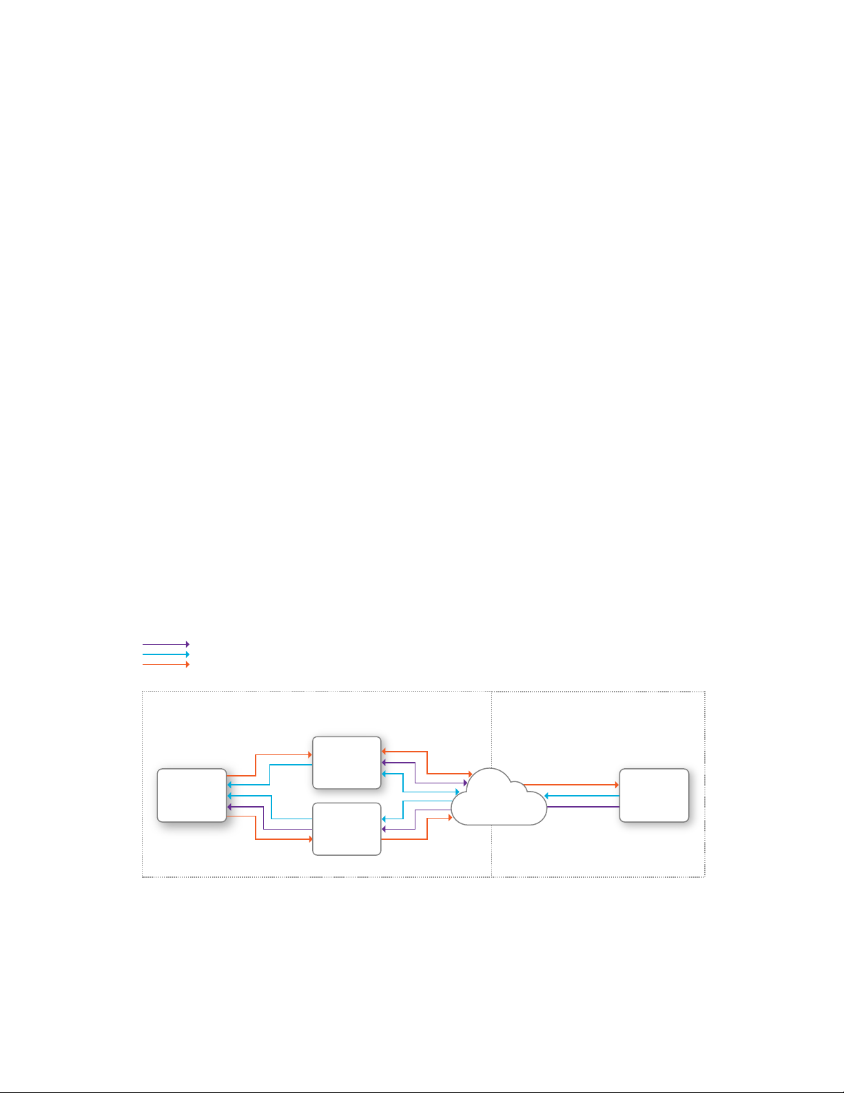
1.1 System Overview
The Solo system includes Solo, the Controller, and the Solo App. As the operator, you interact with the controller
and app on the ground, and the controller communicates with Solo during flight.
1.1.1 Solo
Solo is a small unmanned aerial vehicle (UAV) powered by four motors and four propellers. Solo’s onboard
computers control navigation, attitude, and communications in flight while sending real-time telemetry and video
output and receiving control inputs over the 3DR Link secure Wi-Fi network. Solo is optimized for capturing aerial
video using a GoPro® HERO camera.
1.1.2 Controller
The controller provides control mechanisms and displays in-flight data on a full-color screen. Using twin longrange antennas, the controller acts as the central hub for all communication on the 3DR Link network, receiving all
communications from Solo and the app, forwarding telemetry outputs to the app, and managing the transmission of
all control inputs to Solo.
1.1.3 App
The Solo App outputs a live video stream from an onboard GoPro® camera to an Android or iOS device. The App
allows you to view the live video with overlaid telemetry and access a simplified graphic interface for controlling
Solo’s advanced functions. The App also connects to the 3DR SoloLink network to receive video and telemetry
outputs and send control inputs.
Video output
Telemetry output
Control input
AirGround
3DR Solo
Controller
Operator
3DR Solo
App
Figure 1.1.3.1: Solo System Context Diagram
3DR Link
Secure WiFi
Network
3DR Solo
1.1.4 3-Axis Gimbal
The 3-Axis Solo Gimbal provides greater control of GoPro® HERO cameras. The Gimbal is included, fully installed,
in the package Solo with 3-Axis Gimbal and is also available separately for Solo. This powerful accessory is fully
covered in Chapter 3 of this manual.
1
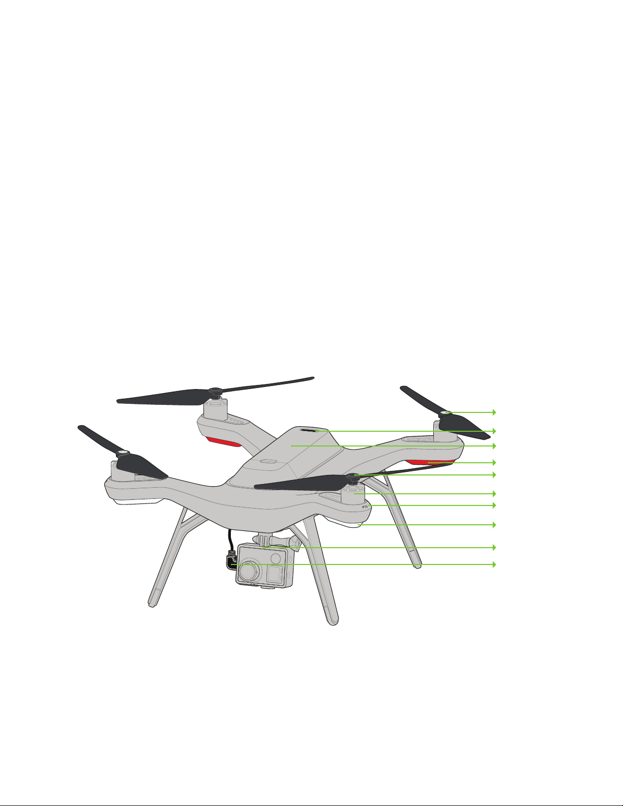
1.2 Aircraft Overview
1.2.1 Smart Battery
The battery connects to Solo’s battery bay. Solo’s power button is located on the battery; Solo can be powered only
when the battery is connected.
1.2.2 Motors and Propellers
Solo’s arms are labeled 1 through 4 on the ends of the arms. Motors on arms #1 and #2 spin counterclockwise
and use clockwise-tightening propellers with silver tops. Motors on arms #3 and #4 spin clockwise and use
counterclockwise-tightening propellers with black tops.
1.2.3 Orientation LEDs
Each arm contains an LED for ground-to-air directional awareness; when armed for flight, the two front arms (#1 and
#3) display white, and the two rear arms (#2 and #4) display red. This LED scheme mimics the headlight and taillight
style of a car.
1.2.4 Fixed Camera Mount and HDMI Cable
Solo includes a GoPro® The Frame fixed mount to mount a GoPro® HERO camera. The HDMI cable connects to
the GoPro® to output video during flight.
Height: 10.2”
Motor-to-motor: 18.1”
Weight (no camera): 3.3 lbs.
Silver-top propeller
Power button
Battery
Rear orientation LEDs
Black-top propeller
Motor
Arm numbering
Front orientation LEDs
Fixed camera mount
HDMI cable
Figure 1.2.4.1: Solo Overview
2

1.3 Controller Overview
1.3.1 Mobile-Device Holder
Mount an Android or iOS device to run the Solo App and effortlessly integrate the App into the controller’s
operational flow. A user-supplied smartphone or tablet is required to initialize Solo and use Smart Shots.
1.3.2 Joysticks
The controller’s left and right joysticks provide direct manual control of Solo and physical control mechanisms for
use with Smart Shots.
1.3.3 Screen
The controller’s full-color screen provides live in-flight data and prompts for certain Solo functions.
1.3.4 Power Button
Press the power button once to check the controller’s battery level. Hold the power button until you see the
controller startup screen to power on the controller.
1.3.5 Fly Button
The Fly button lets you control Solo’s main flight functions: starting motors, takeoff, land, and activating GPS flight.
1.3.6 Return Home
The Return Home button allows you to end your flight automatically at any point by returning Solo to its original
launch point and landing.
1.3.7 Pause Button
The Pause button is Solo’s emergency air brake. Press Pause to stop Solo and hover in place at any time.
1.3.8 Option Buttons
The A and B buttons change functionality based on where you are in the operational flow. The screen shows the
currently assigned functions of A and B at all times. You can program A and B to specific functions using the App.
By default, the A button is assigned to Cable Cam and the B button is assigned to Orbit.
1.3.9 Antennas
The controller’s long-range dipole antennas communicate with Solo during flight. See Section 4.12 for proper
antenna configuration.
1.3.10 Gimbal Controls
Use the paddle, buttons, and dial on the top of the controller are used to control the Solo Gimbal. You can also use
them in some Smart Shots.
3

Antennas
Mobile-device holder
Gimbal controls
Joysticks
Screen
Pause
Return home
Fly
Power
Options
Figure 1.3.10.1: Contr
oller Overview
1.4 Operating Parameters
The following operating parameters apply to Solo. Always operate Solo within these parameters. Solo’s performance
and behaviors may vary significantly if flying in that conditions violate the parameters listed below.
Estimated flight time up to 25 minutes*
Default maximum altitude 150 ft. (46 m) above ground level**
Range .5 mile*** (.8 km)
Payload capacity 1 lb. (450 g)
Cruise speed 18 mph (8 m/s)
Maximum speed 33 mph (15 m/s)****
Wind speed limitation 25 mph (11 m/s)
Operating temperature 32° F - 113° F (0° C to 45° C)
Figure 1.4.1: Solo Operating Parameters
* Flight time varies with payload, wind conditions, elevation, temperature, humidity, flying style,
and pilot skill. Listed flight time applies to elevations less than 2,000 ft above sea level.
** To adjust maximum altitude, see Section 8.7.
*** Depending on environmental conditions
**** This top speed corresponds to Solo when operating in Fly mode. Maximum speeds for advanced
modes may vary; see Section 8.1 for more information.
4

1.5 Autopilot
Solo uses a Pixhawk 2 autopilot running ArduPilot Copter software. ArduPilot is open-source flight control based on
the MAVlink communication protocol. Pixhawk 2 runs an ARM Cortex-M4 STM32F427 processor with 2 MB of flash
memory and 256 KB of RAM. Combined with an array of CAN, I2C, SPI, PWM, and UART interfaces, Pixhawk 2
uses a suite of onboard sensors to calculate Solo’s orientation and motion in flight. This data is input into ArduPilot’s
inertial navigation and position-estimation algorithms and combined with control inputs to send commands to Solo’s
propulsion system.
1.6 Propulsion
Solo uses four brushless 880 Kv motors and four self-tightening propellers for propulsion. For control and
aerodynamic efficiency, two motors spin clockwise and two motors spin counterclockwise. Navigation in the air is
achieved by mixing propulsion of the four motors to actuate flight control along the roll, pitch, and yaw axes.
Each of the four motors is numbered by the marking on the arm. These numbers correspond to the autopilot
calculations for these commands and are used for indicating motor replacement procedures. Each motor is
controlled by an ESC (Electronic Speed Controller) that regulates the rotation of the motors to achieve the speed
commanded by the autopilot.
03
02
Figure 1.6.1: So
lo Motor Order
01
04
1.7 LED Meanings
Solo’s four LEDs indicate its status during startup and in flight.
• Solid white (front) and red (back): Ready to fly, standard flight configuration
• Pulsing white (front) and red (back): Solo is flying under autopilot control
• Flashing red alternating front and back: Controller signal lost
• Flashing rainbow: Update in progress
• Solid green, then turning off one-by-one: Startup successful
• Solid green without turning off automatically: Startup unsuccessful, please restart Solo
5
2 Setup
This section covers everything you need to set up Solo out of the box.
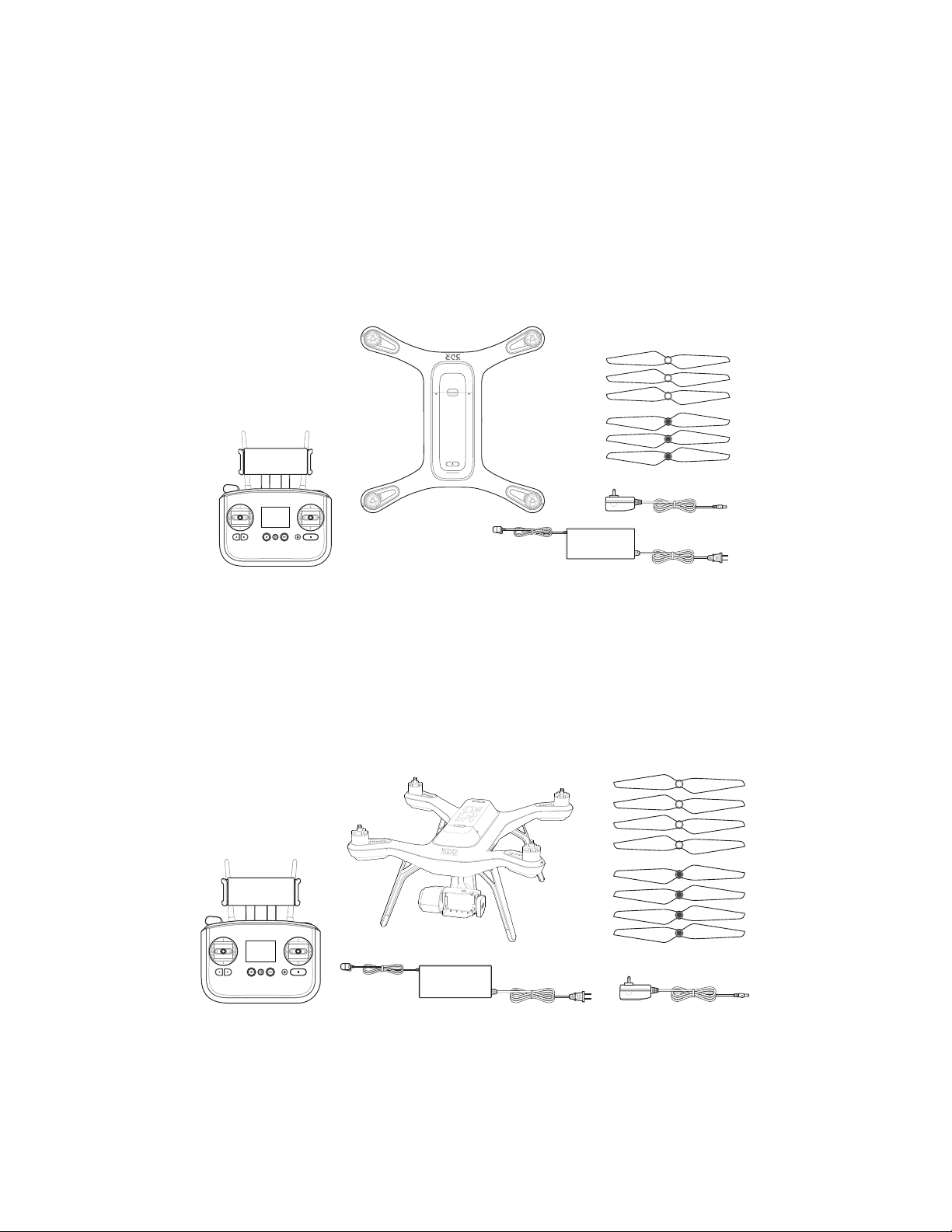
2.1 In the Box - Solo with The Frame
The Solo package includes the Solo Vehicle with The Frame (for mounting a GoPro camera), the Solo Controller,
propellers (four plus two spares), the Solo Smart Battery, the Solo Smart Battery charger, and a charger for the Solo
Controller.
Solo
Controller
Figure 2.1.1: Solo Parts
Three silver-top props
& three black-top props
Controller charger
Solo charger
2.2 In the Box - Solo with 3-Axis Gimbal
The Solo with 3-Axis Gimbal package includes the Solo Vehicle with 3-Axis Gimbal installed, the Solo Controller,
propellers (four plus four spares), the Solo Smart Battery, the Solo Smart Battery charger, and a charger for the Solo
Controller.
Four silver-top props
Solo with Installed Gimbal
& four black-top props
Controller
Figure 2.2.1:
Solo charger
Solo with 3-Axis Gimbal Parts
Controller charger
2.3 Battery
Solo is powered by the rechargeable Solo Smart Battery, which provides up to 25 minutes of flight time per full
charge. (Note: Flight time depends on payload, wind conditions, elevation, temperature, humidity, flying style and
6
pilot skill, so the actual flight time may vary.) As a lithium polymer battery, the Solo Smart Battery requires specific
handling practices to ensure safe operation and prevent accidents. For more information about battery safety, see
Section 4.10, Flight Battery, on page 28.
2.3.1 Charging
The level of the battery charge is indicated by the lights below the power button. Press the power button once to
display the current power level. The Solo Smart Battery ships with approximately 50% charge, so charge fully before
your first flight for maximum flight time.
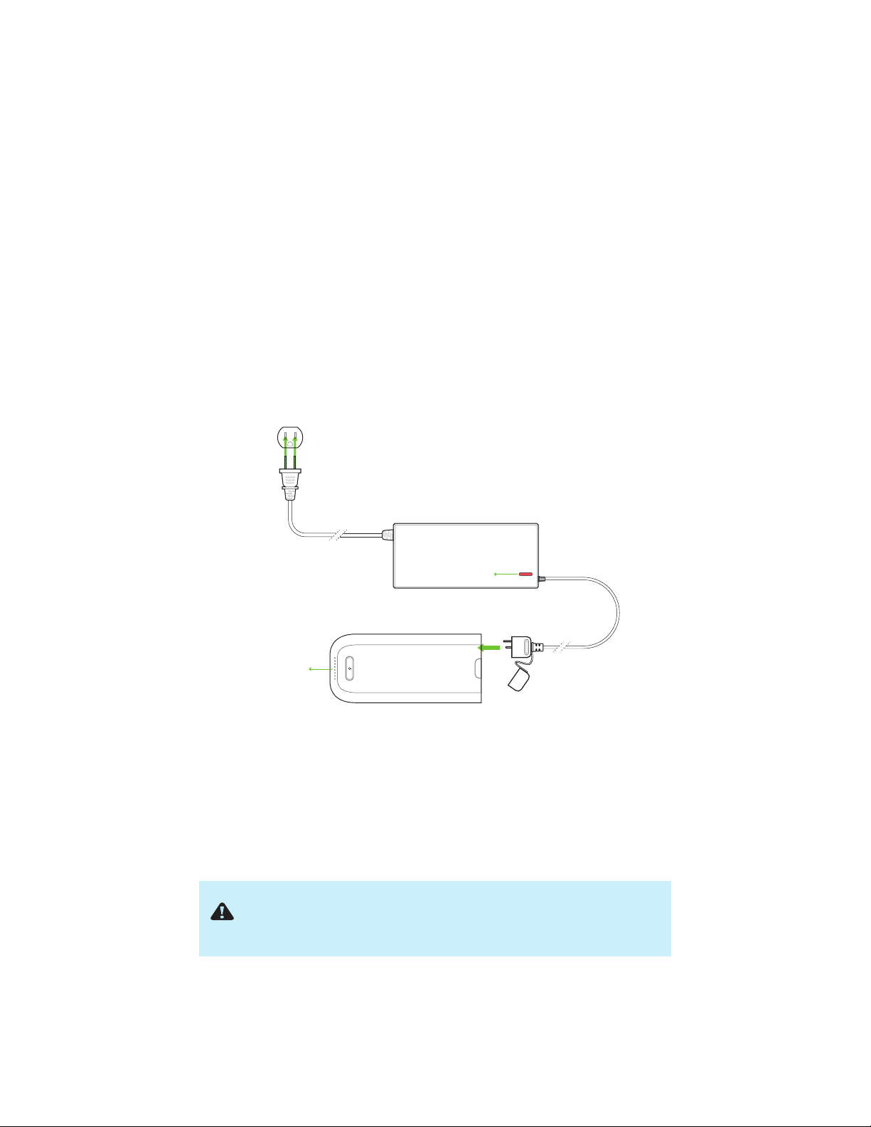
Remove the battery from Solo before charging by holding the release button and sliding the battery towards the
back of Solo. Charge the battery using the designated Solo charger only; using a different charger can damage the
battery or cause a fire.
To charge the battery, connect the Solo charger to the battery and a wall outlet. While charging, the indicator lights
pulse at the current level. An additional indicator on the battery charger turns from red to green when
the battery is fully charged. The battery takes approximately 1.5 hours to charge to 100%.
The optimal storage charge for the Solo Smart Battery is 50%. Storing the Solo Smart Battery at an excessively
depleted charge (7 percent and under) for an extended period might result in shorter battery life or permanent
damage to the battery.
Charge indicator
Charge indicator
Figure 2.3.1.1: Charing
the Solo Smart Battery
2.3.2 Powering
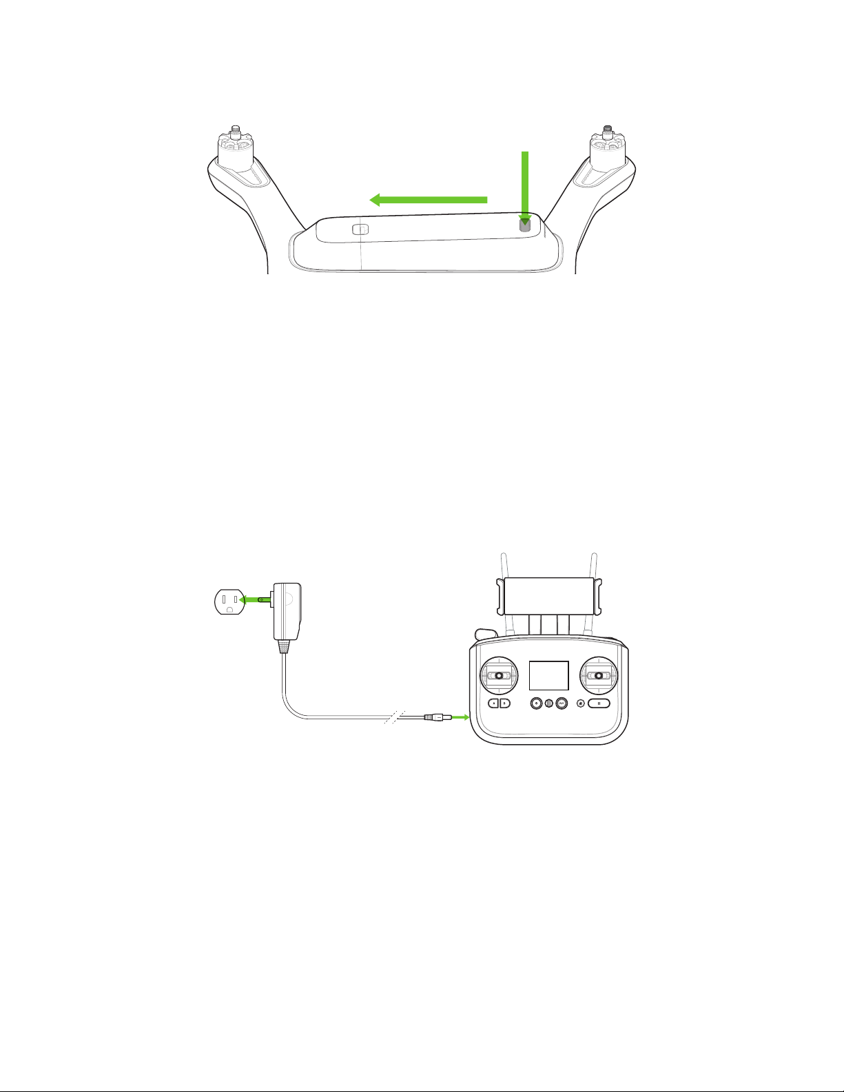
To power Solo, insert the Smart Battery into Solo’s battery bay and slide the battery forward until it clicks into
place. To turn on Solo, press and hold the battery power button. When Solo powers on, the battery displays an
LED animation and you hear the startup tone. Power Solo only with the designated 3DR Solo Smart Battery; using a
different battery can permanently damage Solo.
Before powering on, make sure Solo is level and keep Solo still during
startup and while the sensors initialize. Moving Solo during this
process causes the sensors to calibrate incorrectly and can create a
preflight error or affect in-flight performance.
7
1 Slide to connect
2 Hold to power
Figure 2.3.2.1: Poweri
ng Solo
2.4 Controller
The Solo Controller includes a pre-installed rechargeable lithium ion (Li-ion) battery.
2.4.1 Charging
Charge the controller using the designated controller charger only; using a different charger can damage the
controller or cause a fire.
To charge the controller, connect the controller charger to the barrel jack on the side of the controller and to a
wall outlet. To check the battery level of the controller, press the power button. A fully charged controller lasts for
approximately 6 hours. Always check the controller’s battery level before you fly, and recharge when prompted by
the controller. The controller takes approximately three hours to charge to 100%.
Figure 2.4.1.1: Controller Charging
8
2.4.2 Powering
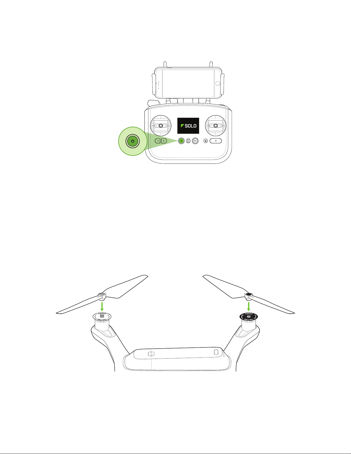
To power on the controller, press and hold the controller power button until you see the startup screen.
Figure 2.4.2.1: Power On Controller
2.5 Propellers
Solo uses two types of self-tightening propellers, indicated by the color of the circle at the center of the propeller.
2.5.1 Attaching
Attach the propellers with silver tops to the motors with a silver dot on the top of the motor shaft, and attach the
black-top propellers to the motors with black dots. Make sure to remove the paper labels from the motors before
attaching the propellers.
Silver-top propellers tighten clockwise; black-top propellers tighten counterclockwise. Check the lock and unlock
icons on each propeller to see the correct directions for tightening and removing.
Figure 2.5.1.1: Attach Propellers
9
2.6 Camera
ORIENTATIONSETUP
OFF
:OFF
:UP
:VIDEO
ORIENTATION
OFF
:OFF
:AUTO
:VIDEO
EXIT
EXIT
RESET CAM
The Solo package includes a fixed GoPro® The Frame™ mount for your GoPro® HERO 3, 3+ or 4.
Note: If you have Solo with 3-Axis Gimbal or have installed the Gimbal separately, see Section 3.2.5, Camera
Installation, on page 19.
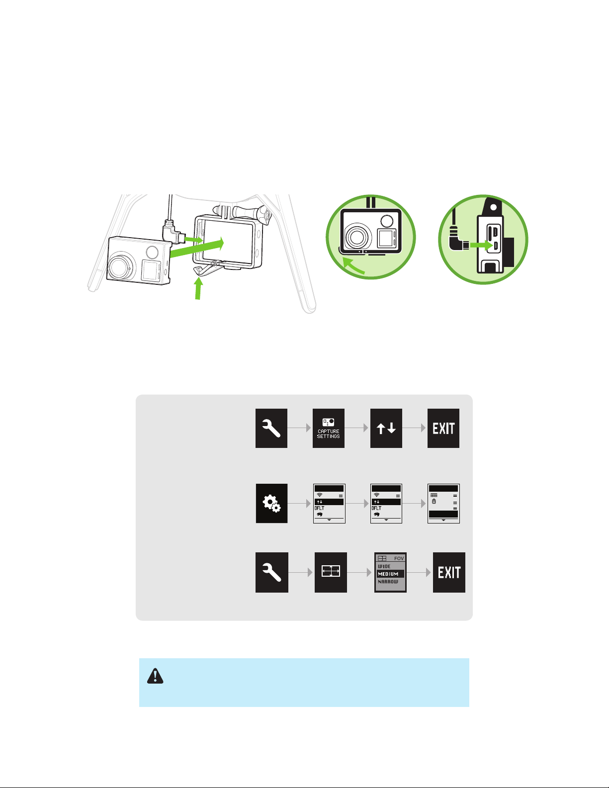
2.6.1 Attaching GoPro to The Frame
To attach the camera to the GoPro® The Frame™ fixed mount, insert your GoPro® upside down and connect the
Solo HDMI cable to the camera.
GoPro® The Frame
Your GoPro®
HERO 3, 3+ or 4
Figure 2.6.1.1: Attach C
™
Mount your GoPro®
upside down.
Connect the HDMI
cable.
amera
2.6.2 Settings
For best results, adjust the camera settings for inverted orientation and medium field of view. (Setting the field of
view to medium ensures that you won’t see the propellers in the frame.)
Set the GoPro® HERO3
to inverted orientation:
Enable GoPro® HERO4
auto-orientation:
Set the GoPro
®
to
GoPro®
Settings
ORIENTATIONSETUP
OFF
:UP
:VIDEO
:OFF
Camera
Orientation
ORIENTATION
OFF
:AUTO
:VIDEO
:OFF
EXIT
RESET CAM
EXIT
medium field of view:
®
GoPro
Settings
Figure 2.6.2.1
: Camera Configuration Process
Make sure the Wi-Fi on your GoPro® is turned OFF. Otherwise, it can
interfere with Solo’s communication signals and cause unexpected
behavior.
10
2.7 Mobile App
The Solo App provides a streaming-video link to a mobile device and a simple graphic interface for using Smart
Shots and other advanced Solo features.
2.7.1 Install
Visit 3dr.com/soloapp or download “3DR Solo” from the App Store or Google Play Store. 3DR Solo works with iOS
8.0 or later and Android 4.3 or later. For Android, you must also install the “3DR Services” app to your device.
2.7.2 Register
The first time you run the App, you’re prompted for registration information and the Solo serial number. You also
have the option to view some intro videos. Once you’ve completed this process, you’re taken to the home screen of
the App.
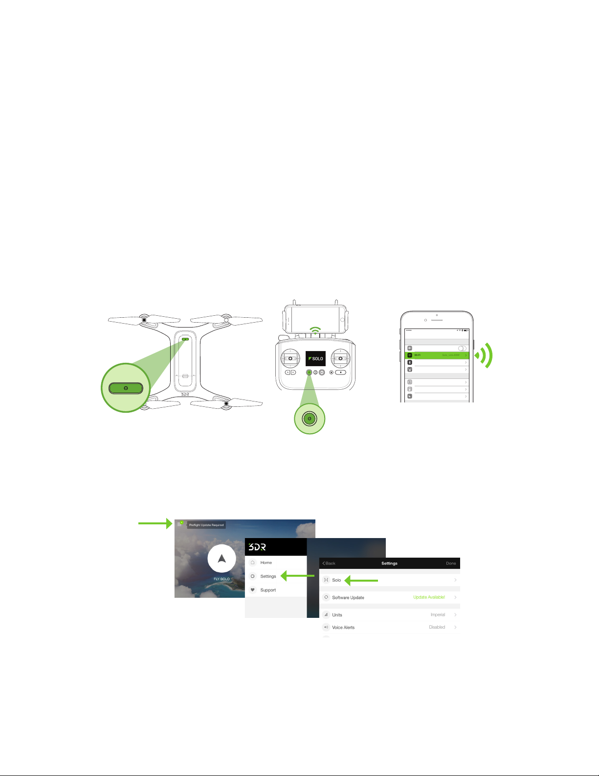
2.7.3 Connect to Solo
To connect the App to Solo’s 3DR Link Wi-Fi network, tap the Connect button on the home page of the App and
follow the prompts. When in the Wi-Fi settings on the mobile device, connect to SoloLink_####. Enter the temporary
password “sololink”. Once connected, return to the app to continue. Both Solo and the controller must be powered
on to connect to the App.
7:34 PMLTE
Settings
Airplane Mode
WI-FI
Solo_Link-####
Bluetooth
Cellular
Notifications
Control Center
Do Not Disturb
On
Figure 2.7.3.1: Connect to So
lo Link
2.7.4 Change SoloLink Password
Once connected to Solo Wi-Fi, change your password to secure your SoloLink network as follows: Access the
Settings section by tapping Settings at the bottom-right of the home screen, then choose Solo to access the
options for your drone.
Figure 2.7.4.1: App - Settings Menu
In the Solo section, select Solo Name & Wi-Fi, and set a new password. The password should be between 8 and 32
characters with no spaces. Select Apply to enable your changes. If you forget your SoloLink password, perform the
factory reset procedure described in Section 10.7 to reset the password to the temporary password (sololink).
11
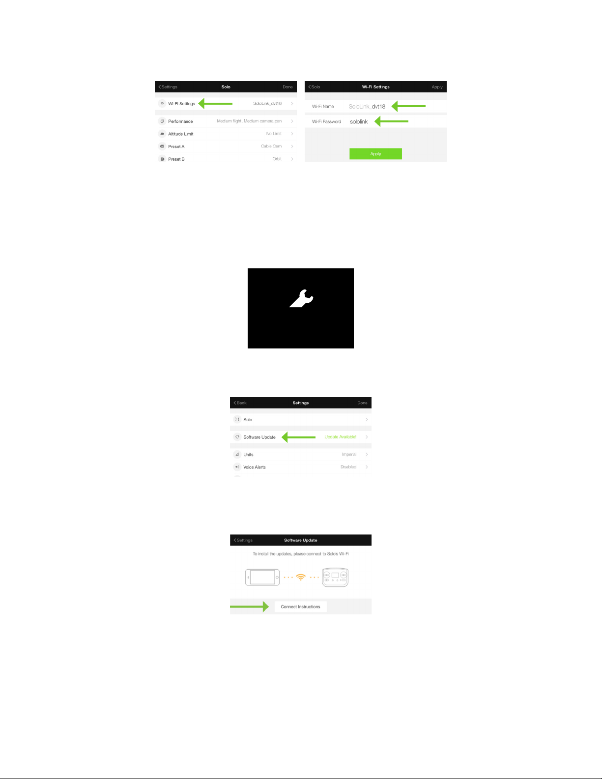
Figure 2.7.4.2: App - Wi-Fi Settings
ARTOO UPDATE SCREEN FEEDBACK V10C
Update Requirement Screen
update error
Solo and Controller have
different software versions
Use 3DR Solo app to update the system
2.7.5 Update
Before your first flight, use the App to perform the required first-flight update of Solo and the Controller. The
Controller will prompt you for the update with the preflight update alert. Ensure that both the controller and Solo
are powered, the Controller has at least 50% battery remaining, and the app is connected to Solo Wi-Fi. The total
update process can take up to 10 minutes.
preflight update
Required before first flight!
Use 3DR Solo App to update
Figure 2.7.5.1: Controller Preflig
ht Update Prompt
To start the update, open the Settings menu in the App, and select Software Update.
Figure 2.7.5.2: App - Software Update
Because your mobile device has never connected to this Solo before, you will need to link your device with Solo
Wi-Fi (SoloLink).
Figure 2.7.5.3: App - Connecting Instructions
12

Then follow these instructions to connect to Solo Wi-Fi:
ARTOO UPDATE SCREEN FEEDBACK V10C
Update Requirement Screen
Controller update in progress screen
Is displayed after user initiates update in app.
Persists until controller update is successful.
preflight update
Required before first flight!
Use 3DR Solo App to update
update error
Solo and Controller have
different software versions
Use 3DR Solo app to update the system
Solo-Artoo version mismatch
If Solo and Artoo have a mismatched version on startup
this message is displayed in the update ow in
place of the “preight update” screen.
Update Timeout
If update does not complete in X minutes
“update-unsuccessful” screen is displayed
Update failure
Figure 2.7.5.4: App - Instructions List
Once connected, return to the App and you will be notified of the current version you are about to update to. To
continue, select Download Update. For this step you will need an Internet connection, either cellular data or Wi-Fi. If
you opt to use Wi-Fi, you’ll need switch from SoloLink to your Wi-Fi network.
Figure 2.7.5.5: App - Download Update
When the App detects an active connection with the controller, it prompt you to begin the update. (Solo and the
controller must be powered on to connect to Solo Wi-Fi.) To start the update, select Begin.
While the update is in progress, the controller shows the controller updating display. The controller completes a full
restart as part of the update process, which can take up to five minutes.
Figure 2.7.5.6: App - Start Update
Controller updating
Update will take about 5 minutes
Please ensure charger is connected
Controller may go dark while updating
Figure 2.7.5.7: Controller - Updating
13
Because the Controller must restart as part of the update process, your device will lose its connection to Solo Wi-Fi.
ARTOO UPDATE SCREEN FEEDBACK V10C
Update Requirement Screen
Controller update in progress screen
Is displayed after user initiates update in app.
Persists until controller update is successful.
Update complete feedback.
Tells the user that controller update was successful.
HAPTIC: Three 20 millisecond pulses,
to communicate update completion.
A-Press required to dimiss (same as current implementation)
Controller updating
Update will take about 5 minutes
Please ensure charger is connected
Controller may go dark while updating
preflight update
Required before first flight!
Use 3DR Solo App to update
update error
Solo and Controller have
different software versions
Use 3DR Solo app to update the system
Solo-Artoo version mismatch
If Solo and Artoo have a mismatched version on startup
this message is displayed in the update ow in
place of the “preight update” screen.
Update Timeout
If update does not complete in X minutes
“update-unsuccessful” screen is displayed
Update failure
If update fails, display “update unsuccessful”
screen
ARTOO UPDATE SCREEN FEEDBACK V10C
Update Requirement Screen
Controller updated
Controller update in progress screen
Is displayed after user initiates update in app.
Persists until controller update is successful.
Update complete feedback.
Tells the user that controller update was successful.
HAPTIC: Three 20 millisecond pulses,
to communicate update completion.
A-Press required to dimiss (same as current implementation)
Controller updating
Update will take about 5 minutes
Please ensure charger is connected
Controller may go dark while updating
Please reconnect to Sololink wifi
Press to continue
preflight update
Required before first flight!
Use 3DR Solo App to update
update error
Solo and Controller have
different software versions
Use 3DR Solo app to update the system
Waiting for Solo
Persists until Solo reconnects
or
Artoo auto-shutdown
Solo-Artoo version mismatch
If Solo and Artoo have a mismatched version on startup
this message is displayed in the update ow in
place of the “preight update” screen.
Update Timeout
If update does not complete in X minutes
Update-unsuccessful screen is displayed
Update Timeout
If update does not complete in X minutes
“update-unsuccessful” screen is displayed
Update failure
If update fails, display “update unsuccessful”
screen
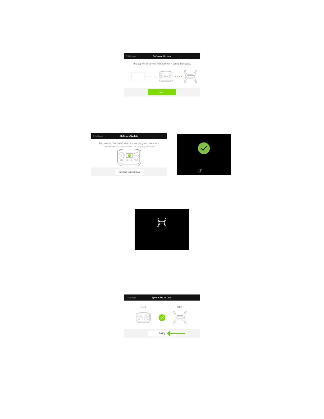
When you see the following screen, select Next to continue.
Figure 2.7.5.8: App - Update Disconnection Confirmation
The Controller restarts and displays a green checkmark to indicate its update was successful. When you see the
green checkmark on the controller, reconnect to Solo Wi-Fi in the app and press A on the controller to continue the
update.
Controller updated
Please reconnect to Sololink wifi
Press to continue
Figure 2.7.5.9: Controller Update Complete Displays
After you press A, Solo restarts to complete the update. While Solo restarts, the controller displays “waiting for
Solo.”
When the update is complete, Solo’s LEDs turn green, the controller returns to the standard takeoff screen, and the
App shows that the software is up to date. After displaying green, Solo’s LEDs return to the standard white-and-red
pattern. If you do not see white-and-red LEDs after a few minutes following the update, restart Solo.
waiting for Solo
Press when LEDs are green
Figure 2.7.5.10: Controller - Waiting for Solo
Figure 2.7.5.11: App - Update Success
14
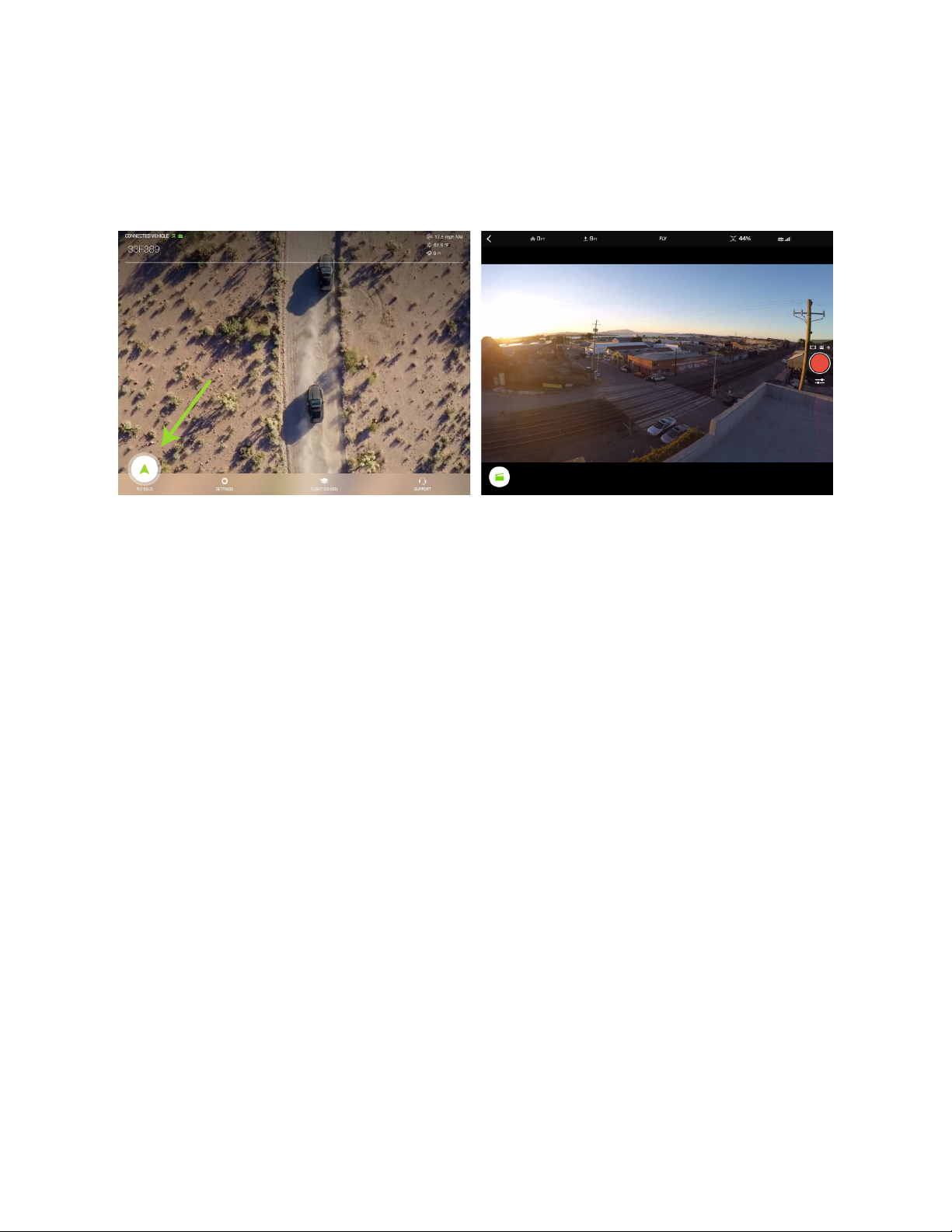
2.7.6 View Video
After the update is complete, to view video in the app, first make sure Solo, the controller, and the GoPro® are
powered on, and that the App is connected to Solo via Wi-Fi. Then, on the App home screen, tap Fly Solo.
Before your first flight, verify that you can see video. If the video is inverted, see section 2.6.
Figure 2.7.6.1: App - Viewing Video
15

3 The Solo Gimbal
The optional Solo Gimbal holds your GoPro® camera and lets you control it remotely. It taps Solo’s intelligence to
get perfectly automated shots, plus rock-solid footage, GoPro® control and charging, and long-range HD video
feed. With the 3-Axis Solo Gimbal, you get:
• Smooth and fluid HD footage every flight.
• Start and stop recording (HERO4 models) while you fly so you can pick and choose the shots you want.
• Footage stabilized to within 0.1 degree of pointing accuracy for enhanced Smart Shots.
• Fine-grain camera tilt control, including angle presets and instant speed adjustment.
Note: If you purchased the Solo with 3-Axis Gimbal package, skip to section “Camera Installation” on page 19.
3.1 In the Box
The Solo 3-Axis Gimbal package includes the Solo Gimbal, the sunshade, four balance weights for the GoPro®
camera, and a screwdriver for installing the Gimbal.
Sunshade Screwdriver
Solo Gimbal
Figure 3.1.1: Solo Gimbal Parts
To install the Solo Gimbal and start utilizing its features, follow these Solo Gimbal installation instructions:
Balance weights (4)
3.2 Gimbal Installation
Before installing the Solo Gimbal, make sure the firmware on Solo and your GoPro as well as the Solo App on your
mobile device are up to date for the best performance.
Recommended versions:
• Solo: 1.2.0 or higher
• Solo App: 1.2.0 or higher
• GoPro: 3.00.00 or higher
3.2.1 Remove The Frame
1. Flip Solo over to access the bottom of the vehicle.
2. The Frame is secured to Solo by three captive screws (permanently attached to the mount to prevent losing
them). Since these screws don’t come out all the way, loosen each screw until they can’t be backed out any
further.
3. Detach the mount from Solo by gently lifting up on it.
4. Route the HDMI cable out through the mount to complete the separation.
16
Turn over Solo.
Gently
detach
the plate.
Loosen the three screws
securing the mount.
Figure 3.2.1.1: Removing The Fram
Free the cable,
and remove the mount.
e
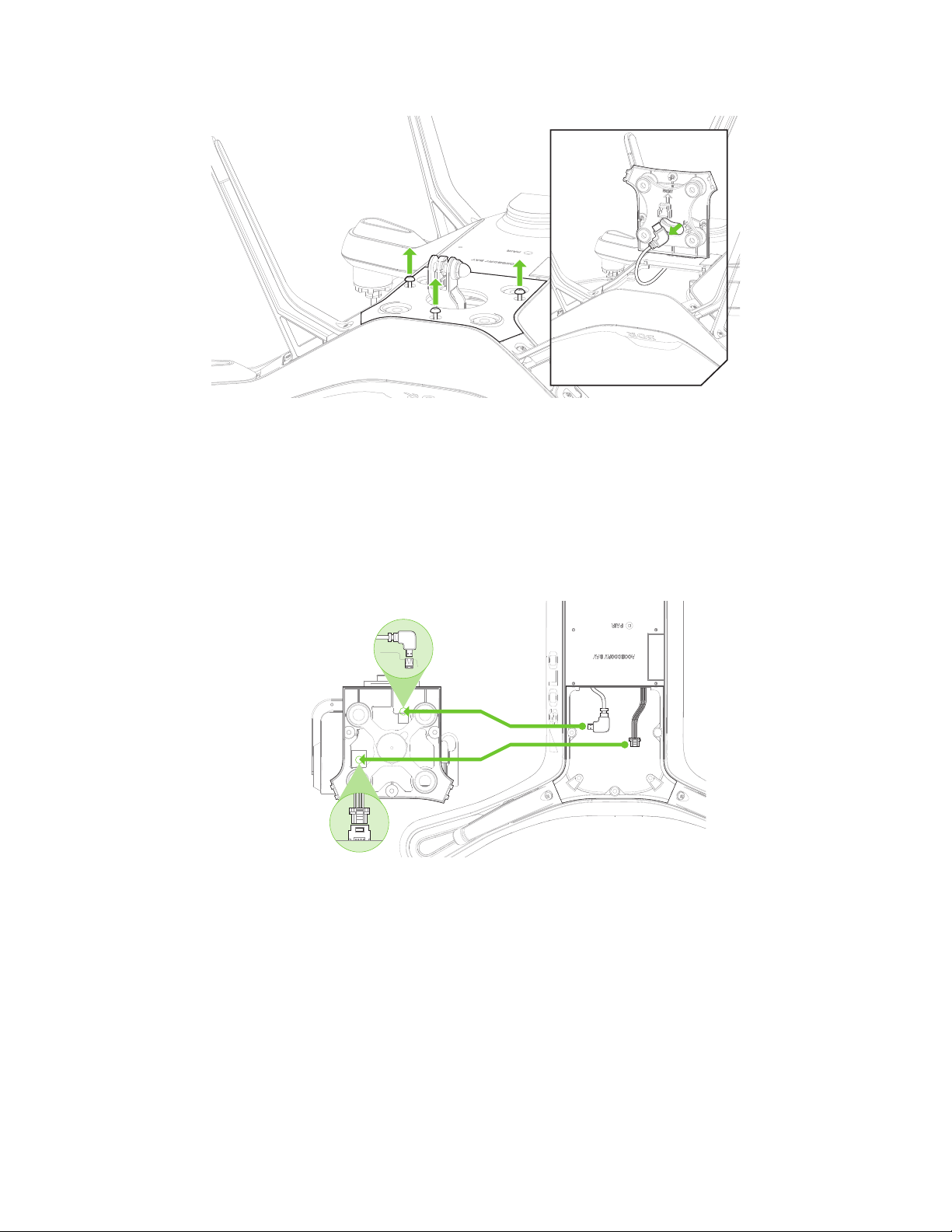
3.2.2 Connect Gimbal
1. Remove the foam insert holding the gimbal in place and set it to the side (this piece is used to help protect
the gimbal during travel).
2. On the bottom of the gimbal plate are two ports: one for the HDMI cable and one for the gimbal cable. Plug
in the cables running from Solo to their respective ports on the gimbal, as shown following.
Connect
HDMI cable.
Connect
gimbal cable.
Figure 3.2.2.1: Connecting cables
3.2.3 Position Cables
With both cables now connected to the Solo Gimbal, it is important to position each cable out of the way of other
internal components. When configuring the HDMI and gimbal cables, the HDMI cable should rest on top of the
gimbal cable.
1. Position the gimbal cable out out of the way by pushing any slack towards the front of the Solo Shell.
17
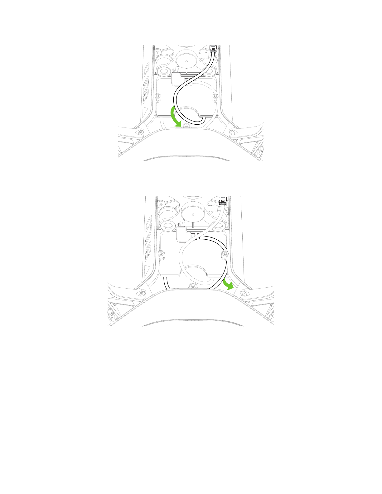
Tuck the Gimbal Cable’s slack
into the front of the Solo body
Figure 3.2.3.1: Positioning the Gimbal Cable
2. Loop the HDMI cable around and inside the front of the body, pushing any extra slack towards the pocket of
Arm #01 as seen below.
Tuck the HDMI Cable’s slack
into the side of the Solo body
Figure 3.2.3.2: Positioning the HDMI Cable
3.2.4 Mount the Gimbal
1. Position the gimbal plate over the opening in the Solo Shell, making sure that the three screw positions are
aligned (two in the back and one in front).
2. Slide the back of the plate in first, and then pinch the two front prongs in and down to insert the plate.
18
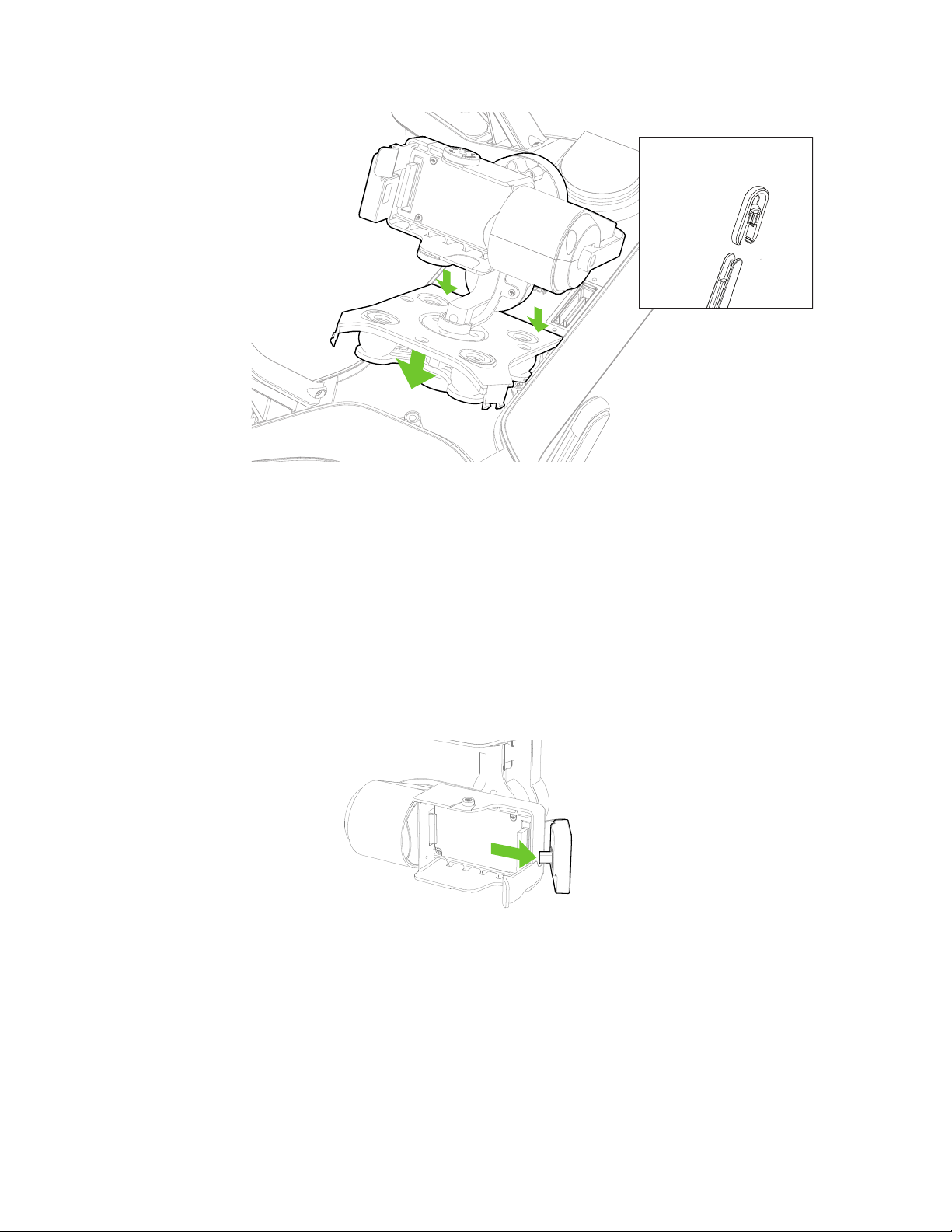
Have extended feet? (Optional)
Install for added clearance.
Figure 3.2.4.1: Mounting the Gimbal
3. When the plate is inserted and resting flush with the Solo Shell, tighten each of the three captive screws.
If the plate isn’t resting flush with the Solo Shell, the most likely cause is that the screws didn’t catch correctly. If the
screws are misaligned, do not try to tighten them. Back out any crooked screws with the screwdriver, then realign
them manually before tightening with the screwdriver.
3.2.5 Camera Installation
The 3-Axis Solo Gimbal holds your GoPro® HERO 3, 3+ or 4. To install your GoPro camera, follow these directions:
1. To create space for your GoPro inside the camera housing, move the the rubber HDMI plug out and away
from the camera housing.
Figure 3.2.5.1: HDMI Plug Positioning
2. Slide your GoPro into place from the front and gently press it in until it is flush with the back of the camera
housing.
19
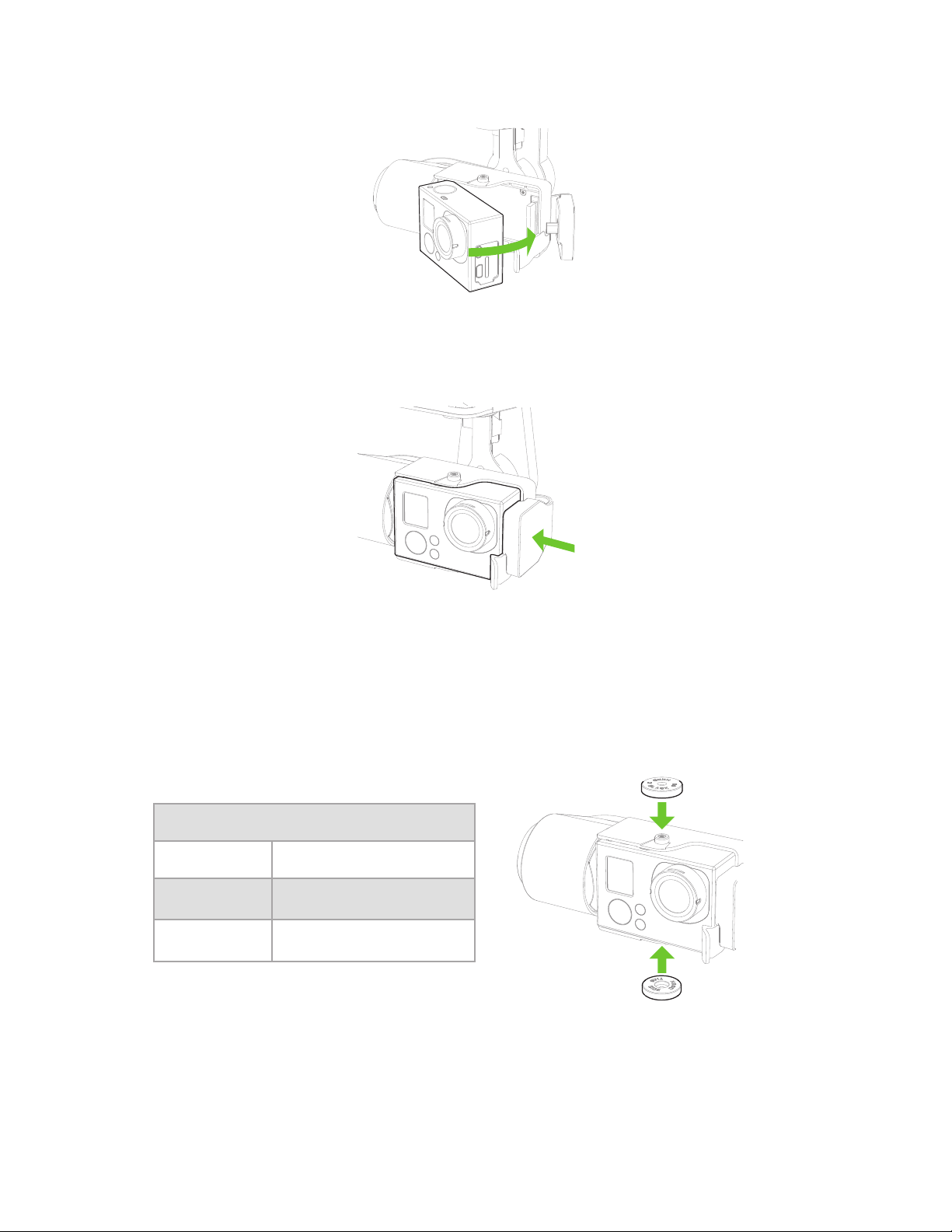
Figure 3.2.5.2: Attach GoPro
3. Take the rubber HDMI plug and insert into the exposed side of your GoPro. This simultaneously fastens the
GoPro into place and secures the HDMI connection. Your GoPro is now installed!
Figure 3.2.5.3: Fasten Camera
3.2.6 Add Balance Weights
Out of the box, the Solo Gimbal is perfectly weighted for use with the GoPro HERO4 Black. If you are using the
GoPro HERO4 Silver or the GoPro HERO3+, then you need to add balance weights to optimize these cameras for
use with the Solo Gimbal. To balance your GoPro, attach the corresponding balance weights to the threaded inserts
on the top and bottom of the camera housing, as shown following.
GoPro Weight Balancing
HERO4 Black No blalance weights needed
HERO4 Silver Add the 2.7g balance weights
HERO3+ Silver Add the 6g balance weights
®
Figure 3.2.6.1: GoPro Weight Balancing
20
 Loading...