

Page 1
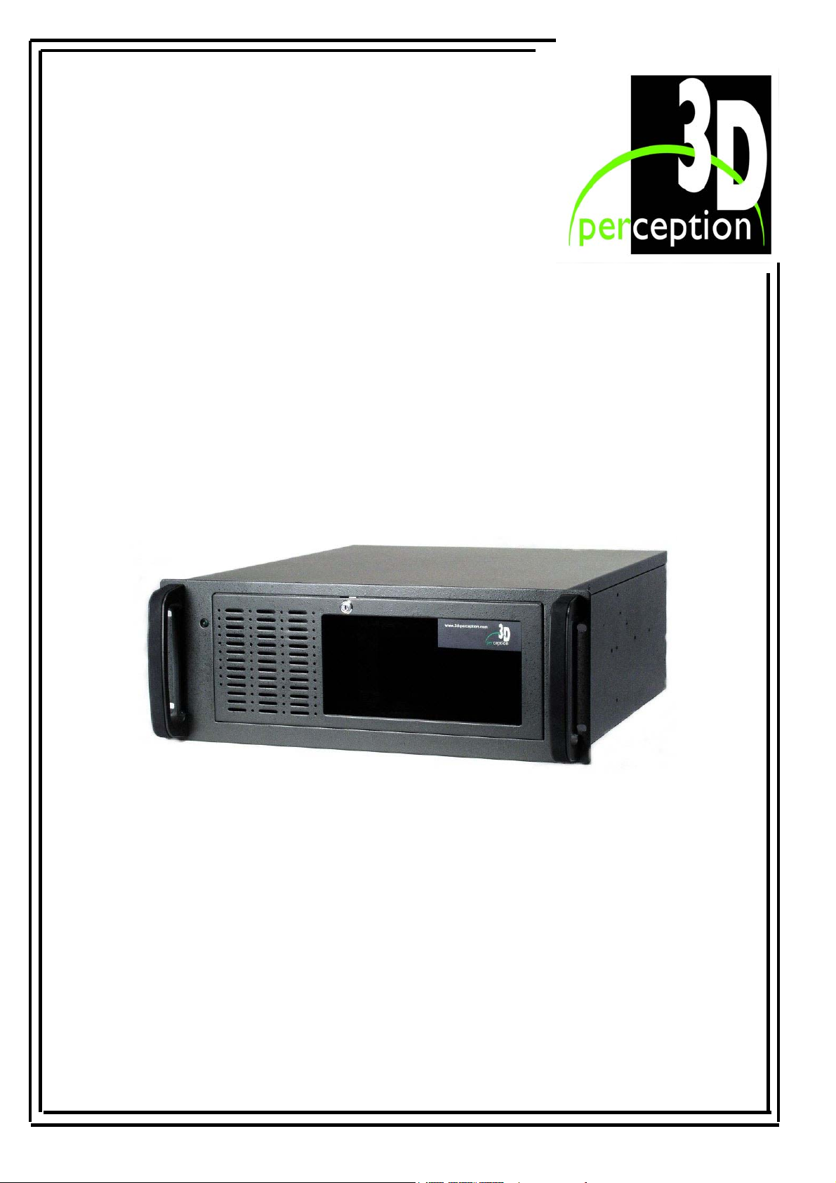
CompactUTM
USER MANUAL
2002 3D Perception AS All rights reserved.
The copyright of this document is the property of 3D Perception AS. The document is supplied on the
express terms that it is to be treated as confidential. No part of this document may be reproduced or
transmitted in any form or by any means, electronic or mechanical for any purpose, without the
express written permission of 3D Perception AS. The information in this document is subject to
change without notice and is provided ‘AS IS’.
Page 2
3D Perception CompactUTM
Revision 6 User Manual
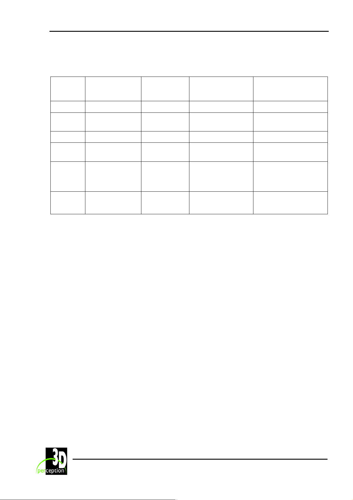
DOCUMENT STATUS
Revision Month Year Paragraph(s) Prepared by Description of
Change
1 October 2001 All A F Rotheram Initial release
2 January 2002 3, 5 and 7 A F Rotheram Update drivers, update
connections
3 February 2002 3 A F Rotheram Rear panel
4 May 2002 7 and 8 A F Rotheram Plug and Play data in
Monitors
5 July 2002 4, 5 + A F Rotheram Cable assemblies
Update GCM Drivers
new para.
6 October 2002 10 + A F Rotheram New Chapter
Registry Variables
ii
Page 3

3D Perception CompactUTM
Revision 6 User Manual
T
ABLE OF CONTENTS
1. I
MPORTANT NOTICES...............................................................................................................1
1.1 Transportation............................................................................................................... 1
1.2 Unauthorised maintenance ...........................................................................................1
1.3 Unauthorised software..................................................................................................1
2. B
3. G
EFORE YOU START .................................................................................................................2
ETTING STARTED WITH COMPACTUTM ................................................................................3
3.1 Rear panel .....................................................................................................................3
3.2 Connection options .......................................................................................................4
3.2.1 Option
3.2.2 Option
I .......................................................................................................................4
II.....................................................................................................................4
3.2.3 Option III.................................................................................................................. 5
3.2.4 Option
4. C
ABLE ASSEMBLIES ................................................................................................................6
IV.....................................................................................................................5
4.1 Cable Assemblies (Plug to Plug)..................................................................................6
4.1.1 Standard supply ............................................................................................................6
4.1.2 Alternatives (may be ordered separately).....................................................................6
4.2 Adapters........................................................................................................................6
5. C
OMPACTUTM SOFTWARE.....................................................................................................8
5.1 Installing CompactControl/CompactDesigner on the CompactUTM .......................... 8
6. UPDATE GCM DRIVERS ..........................................................................................................9
6.1 Download new drivers from web .................................................................................9
Step 1. Access 3D Perception web .................................................................................................9
Step 2. Enter Support Area.............................................................................................................9
Step 3. Locate Driver Updates.......................................................................................................10
Step 4. Request save to computer.................................................................................................10
Step 5. Select location for save......................................................................................................10
Step 6. Download complete...........................................................................................................11
iii
Page 4

3D Perception CompactUTM
Revision 6 User Manual
6.2 Update drivers.............................................................................................................11
Step 1. Start ...................................................................................................................................11
Step 2. Select the Control Panel ....................................................................................................12
Step 3. Select the System Device ..................................................................................................12
Step 4: Select Hardware ................................................................................................................12
Step 5. Select the Device Manager................................................................................................13
Step 6. Select Image Geometry Processor.....................................................................................13
Step 7. Select Update Driver .........................................................................................................14
Step 8. Hardware Update Wizard..................................................................................................14
7. C
OMPACTCONTROL/COMPACTDESIGNER SOFTWARE ...........................................................17
7.1 About CompactControl/CompactDesigner.................................................................17
7.2 Installation ..................................................................................................................17
7.3 Software License ........................................................................................................18
8. P
9. S
LUG AND PLAY DATA IN MONITORS .................................................................................... 19
ET-UP SCENARIOS ...............................................................................................................20
9.1 CompactControl/CompactDesigner in Laptop ...........................................................20
9.2 CompactControl/CompactDesigner in CompactUTM ...............................................21
9.3 Typical System Scenario with Stereo.........................................................................22
10. R
EGISTRY VARIABLES ...........................................................................................................23
11. MAINTENANCE ......................................................................................................................28
12. L
IMITED WARRANTY, ‘FCC STATEMENT’ AND ‘TRADEMARKS COPYRIGHT’ .......................29
13. C
ONTACT US..........................................................................................................................31
iv
Page 5

3D Perception CompactUTM
Revision 6 User Manual
1. IMPORTANT NOTICES
The warranty card or copy of invoice is your proof of purchase. Please make sure that the
warranty card is returned in order to get the warranty service you are entitled to.
Failure to return the warranty card may void your warranty.
1.1 Transportation
Please use caution when transporting the unit.
1.2 Unauthorised maintenance
Tampering with or opening the CompactUTM can be dangerous. Leave maintenance to
authorised 3D Perception service personnel. Please contact your Value Added Reseller with
any service or maintenance questions you may have.
1.3 Unauthorised software
The installation of software onto the 3D Perception CompactUTM, other than that issued by 3D
Perception will automatically render the warranty ‘Null and Void’.
WARNING
THE UNIT HAS BEEN PRE-SET TO 230 VOLTS.
TO CHANGE TO 110 VOLTS RE-SET SWITCH AT REAR OF UNIT.
1
Page 6

3D Perception CompactUTM
Revision 6 User Manual
2. BEFORE YOU START
THANK YOU FOR CHOOSING THE 3D PERCEPTION COMPACTUTM
Please take a few minutes to make sure that your CompactUTM pack contains all the
necessary parts. Depending on the model you have chosen your pack will contain:
Model/Type
1 Channel
2 Channel
3 Channel
4 Channel
CompactUTM Keyboard
1 1 1 1 1
1 1 1 2 2
1 1 1 3 3
1 1 1 4 4
Quantities
Mouse
Cable Assemblies
DVI-D to DVI-D DVI-A to VGA
CompactUTM
Keyboard Mouse
DVI-Digital to DVI-Digital
single link cable assembly
DVI-A to VGA
cable assembly
2
Page 7

3D Perception CompactUTM
Revision 6 User Manual
3. GETTING STARTED WITH COMPACTUTM
3.1 Rear panel
On/Off
switch
Voltage
switch
Power
supply
Input
channels
Output
channels
Mouse
Keyboard
Parallel
(Shutter glasses port)
USB x2
Video Serial A
LAN
Line in
Line out
Microphone
USB x2
NOTE: Number of Input/Output channels will vary according to the configuration, however
when connecting projectors the convention is to connect them in sequence, 1, 2, 3 and 4 starting
from the left hand side, as viewed from the rear of the unit.
3
Page 8
3D Perception CompactUTM
Revision 6 User Manual
3.2 Connection options
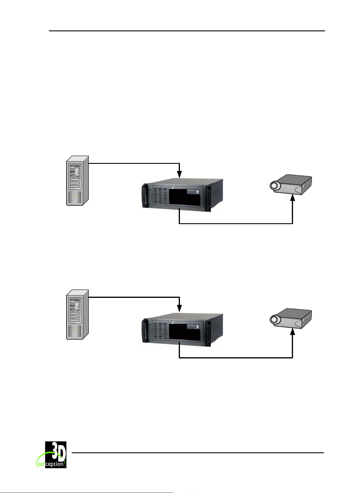
The top socket on the PCB is the input port, the bottom socket being the output port. Both
Digital and Analogue signals may be received and transmitted through the appropriate sockets on
the PCB. The
has been introduced to the socket. Both Digital and Analogue signals will be active on the output
port.
CompactUTM will automatically determine the type of input signal after the plug
3.2.1 Option
I
Option I is an Image Generator with a Digital Video output connected via the CompactUTM to a
Projector with a Digital Video input.
Projector with a
Digital Video
input
Image generator
with a Digital Video
output
DVI-D to DVI-D
cable assembly
CompactUTM
DVI-D to DVI-D
cable assembly
3.2.2 Option
II
Option II is an Image Generator with a Digital Video output connected via the CompactUTM to a
Projector with an Analogue Video input.
DVI-D to DVI-D
cable assembly
Image generator
with a Digital Video
output
4
CompactUTM
Projector with an
Analogue Video
input
DVI-D to VGA
cable assembly
Page 9
3D Perception CompactUTM
Revision 6 User Manual
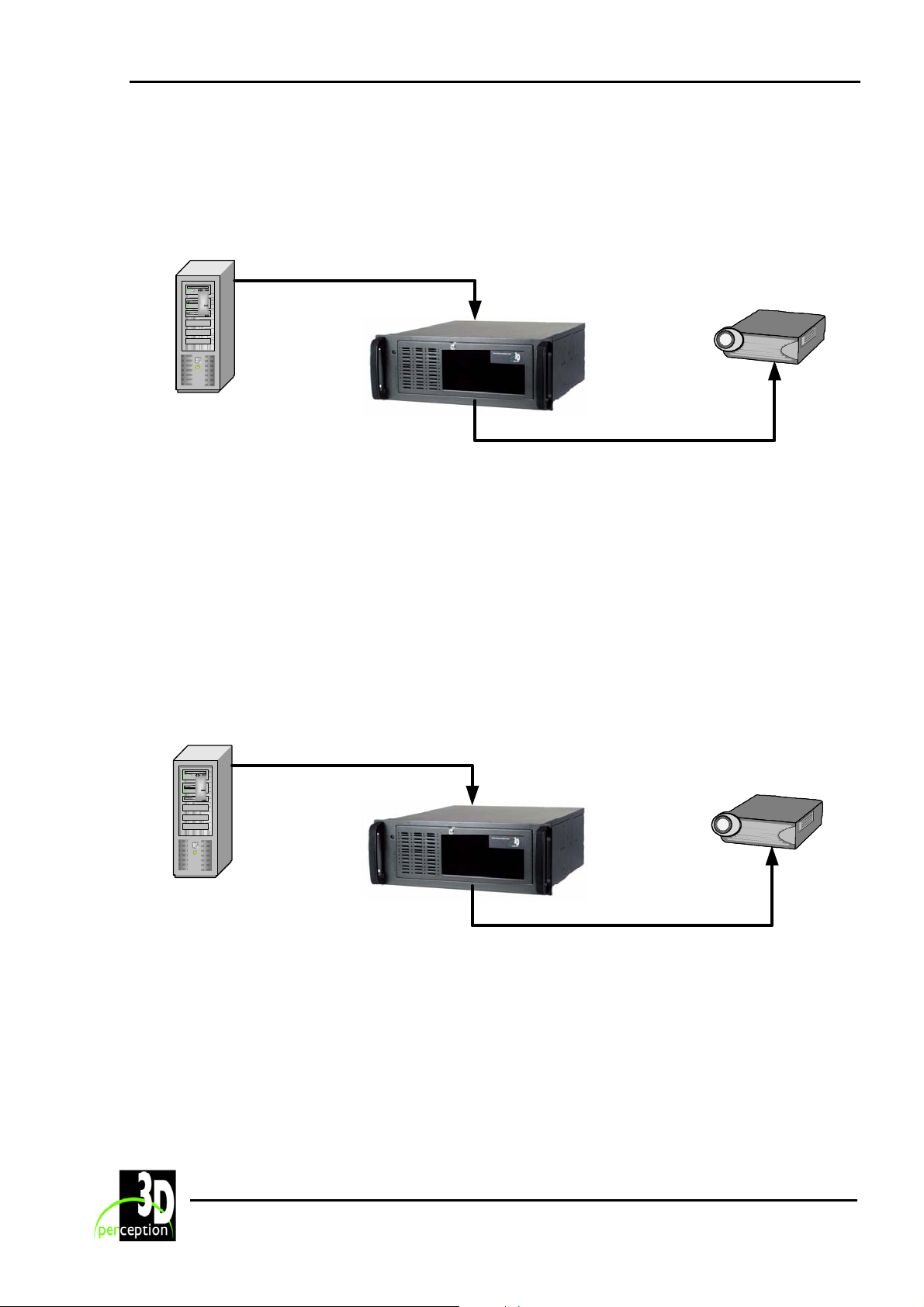
3.2.3 Option
III
Option III is an Image Generator with an Analogue Video output connected via the
CompactUTM to a Projector with a Digital Video input.
Projector with a
Digital Video
input
Image generator
with an Analogue
Video output
DVI-A to VGA
cable assembly
CompactUTM
DVI-D to DVI-D
cable assembly
NOTE:
1. Optionally, instead of using a DVI-A to VGA cable assembly, it is possible to use a DVI-A
to DVI-A cable assembly with a DVI-A to VGA adapter at one end.
2. If it is necessary to connect from the Image Generator via a Sync Separator to the
CompactUTM, connection from the Image Generator to the Sync Separator will be with a
BNC cable and from the Sync Separator to the
CompactUTM will be with a VGA-A to
DVI-A cable.
3.2.4 Option IV
Option IV is an Image Generator with an Analogue Video output connected via the
CompactUTM to a Projector with an Analogue Video input.
Projector with an
Analogue Video
input
Image generator
with an Analogue
Video output
DVI-A to VGA
cable assembly
CompactUTM
DVI-A to VGA
cable assembly
NOTE:
1. Optionally, instead of using a DVI-A to VGA cable assembly, it is possible to use a DVI-A
to DVI-A cable assembly with a DVI-A to VGA adapter at one end.
2. There is a possibility when using Option IV of suffering a loss of image clarity.
5
Page 10
3D Perception CompactUTM
Revision 6 User Manual
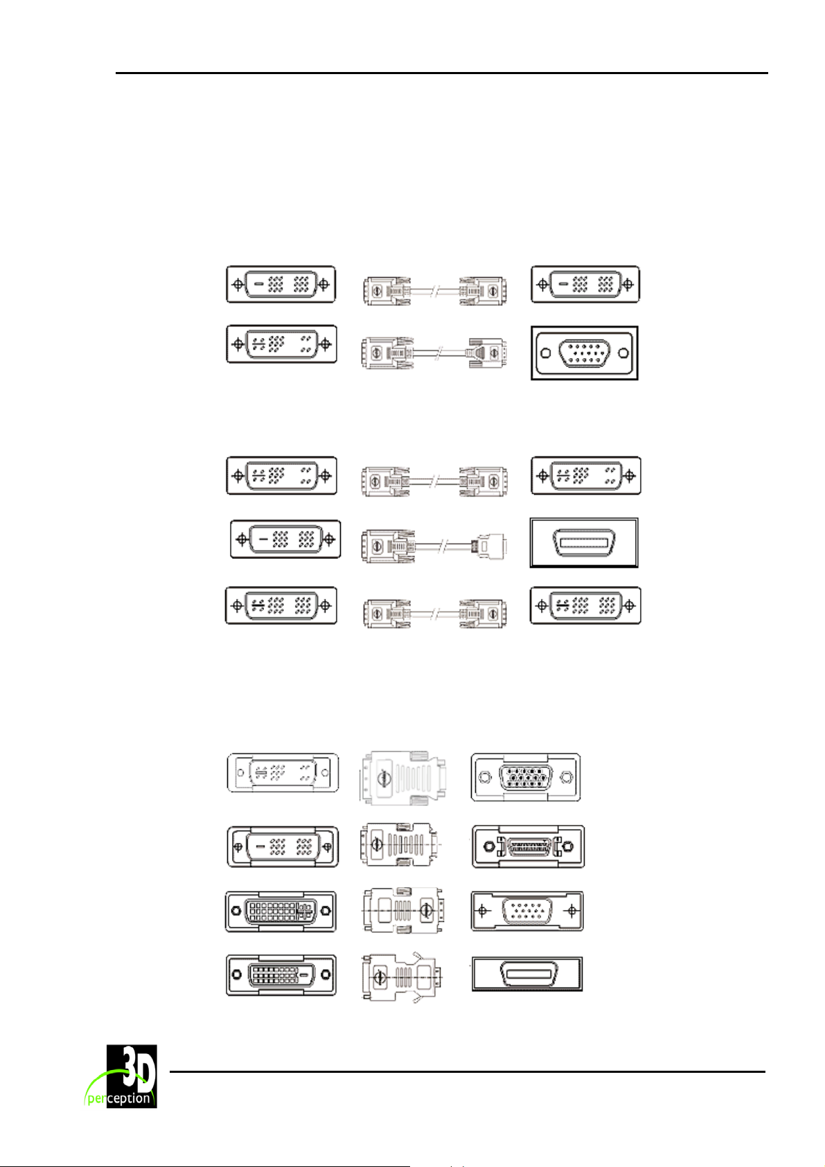
4. CABLE ASSEMBLIES
4.1 Cable Assemblies (Plug to Plug)
4.1.1 Standard supply
DVI-D
(Digital)
DVI-A
(Analogue)
4.1.2 Alternatives (may be ordered separately)
DVI-A
(Analogue)
DVI-D
(Digital)
DVI-I
(Analogue/
Digital)
NOTE: All cable assemblies are plug to plug, male ends.
DVI-D
(Digital)
VGA
(Analogue)
DVI-A
(Analogue)
DFP
(Digital)
DVI-I
(Analogue/
Digital)
4.2 Adapters
The following listed adapters are not standard supply but may be ordered separately.
DVI-A
Plug
DVI-D
Plug
DVI-A
Receptacle
DVI-D
Receptacle
6
VGA
Receptacle
DFP
Receptacle
VGA
Plug
DFP
Plug
Page 11

3D Perception CompactUTM
Revision 6 User Manual
DVI-A
Receptacle
DVI-D
Plug
NOTE: All adapters are passive. They do not function as digital to analogue converters.
7
Page 12

3D Perception CompactUTM
Revision 6 User Manual
5. COMPACTUTM SOFTWARE
To enable the CompactUTM to communicate with the CompactControl/CompactDesigner
software over a Local Area Network (LAN), the LAN to Driver communication module must be
installed. This module is pre-installed when the CompactUTM is delivered.
5.1 Installing CompactControl/CompactDesigner on the
CompactUTM
First, un-install the LAN to Driver communication (from the Control Panel, select Add/Remove
Programs), since this will no longer be needed if CompactControl/CompactDesigner is to be
installed.
Install CompactControl/CompactDesigner from the CD.
During the installation procedure, when asked for communication options, make sure you select
the Processor cards in this machine option for communication in order to enable
CompactControl/CompactDesigner to communicate with the processor cards.
8
Page 13
3D Perception CompactUTM
Revision 6 User Manual
6. UPDATE GCM DRIVERS
The Geometry Correction Module (GCM) Driver is a Plug-and-Play device driver, and will be
loaded by the system when the Geometry Processor cards are first installed. The driver
contains all the functionality for the system to operate.
Updates to the GCM Drivers will typically be downloaded from our web site but may be issued
on CD-ROM. The following steps will enable you to update the GCM Drivers.
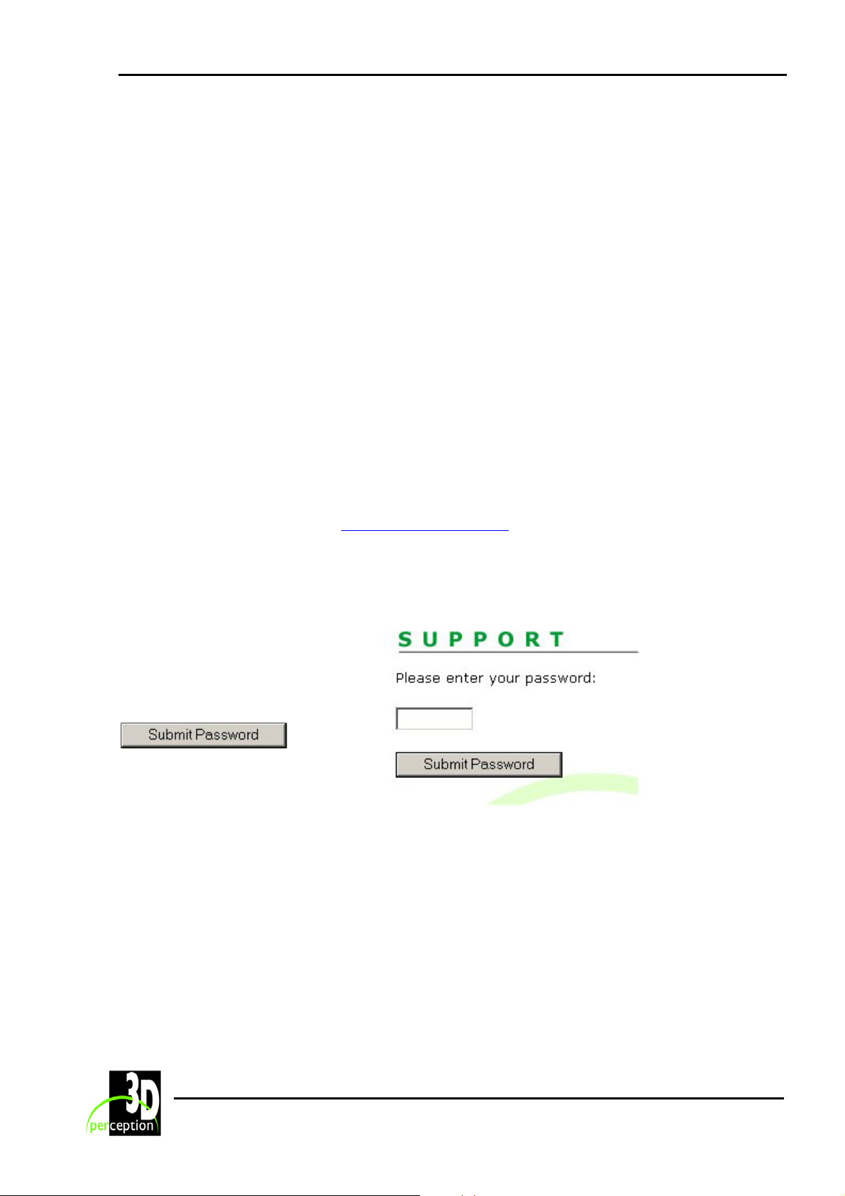
If the updates to the GCM Drivers are to be downloaded from our web site the section entitled Download new drivers from web must be performed. This only needs to be done once for each new driver update.
The section entitled Update drivers that guides you through updating your drivers must be
repeated for each ‘Channel’ on your CompactUTM
6.1 Download new drivers from web
Step 1. Access 3D Perception web
Access 3D Perception’s web
site.
www.3d-perception.com
Step 2. Enter Support Area
Locate and enter the Support area
on 3D Perception’s web site.
Enter the password and click the
Submit Password button.
NOTE: The password can be
obtained from the 3D Perception
customer support desk :
Tel: +47 66 98 70 74
9
Page 14
3D Perception CompactUTM
Revision 6 User Manual
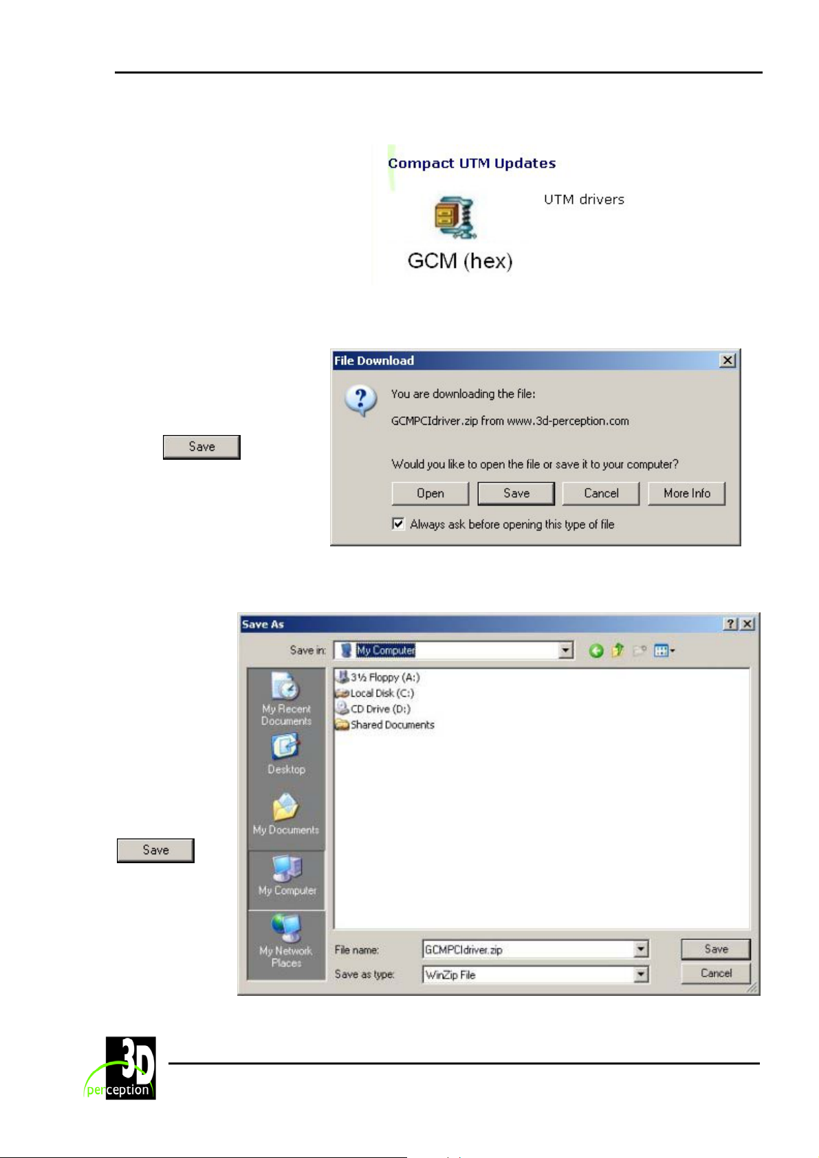
Step 3. Locate Driver Updates
Locate the area with the
CompactUTM Updates and click on
the GCM (hex) icon.
Step 4. Request save to computer
The File Download dialogue
box will identify the driver to
be downloaded.
Select
download into a folder of your
own choice on your
computer.
to
Step 5. Select location for save
From the Save
As dialogue
box select and
area and folder
in which you
want to save
the
downloaded
file.
Click
10
Page 15
3D Perception CompactUTM
Revision 6 User Manual
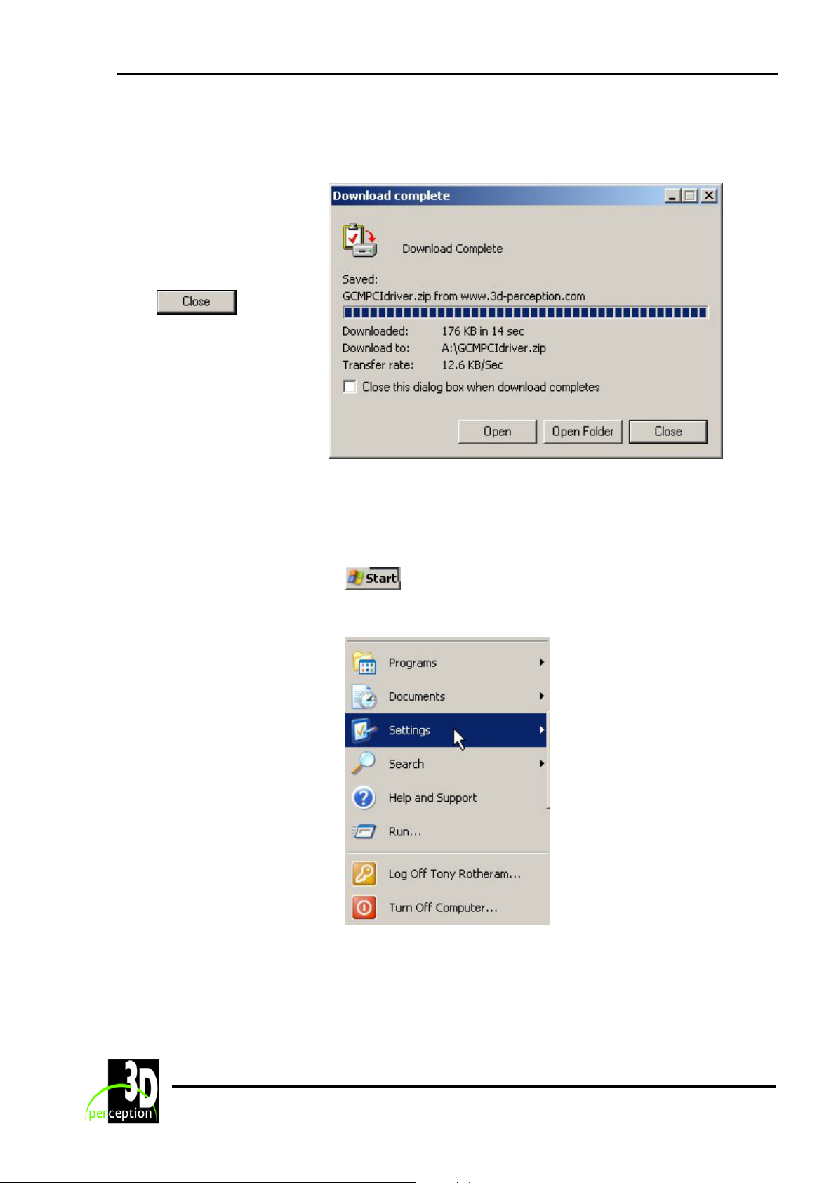
Step 6. Download complete
The Download complete
dialogue box will identify the
successfully downloaded
file.
Click
complete the transaction.
NOTE: The downloaded file
is a ‘zipped’ file and must
now be ‘unzipped’.
to
6.2 Update drivers
This section must be performed for each separate channel.
Step 1. Start
Select the Start button at the
bottom left hand corner of your
screen
Select Settings from the drop
down menu
11
Page 16
3D Perception CompactUTM
Revision 6 User Manual
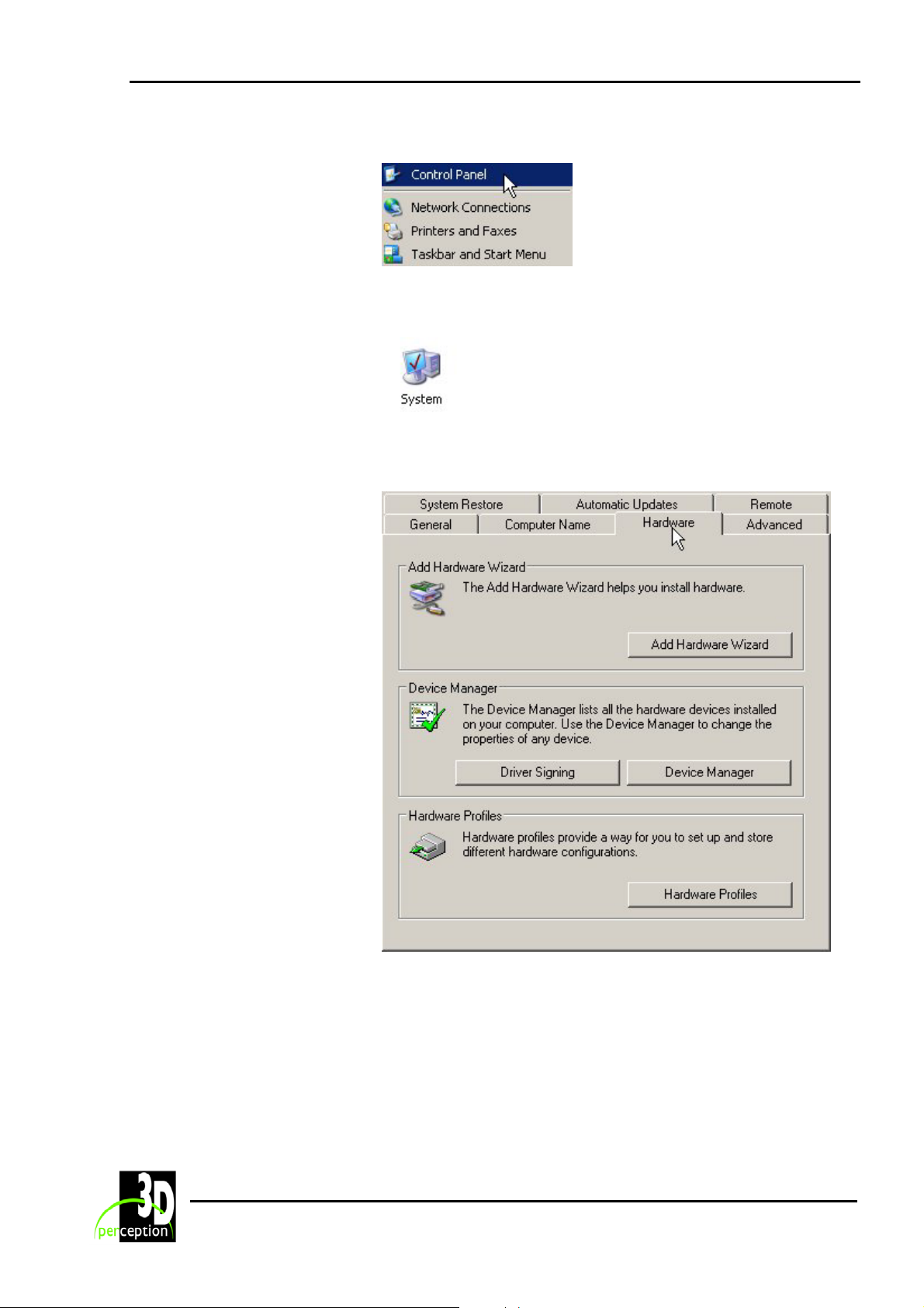
Step 2. Select the Control Panel
Click on Control Panel on the
drop down sub-menu
Step 3. Select the System Device
Locate the System device
icon on the Control Panel and
double click on it.
Step 4: Select Hardware
From the System Properties
dialogue box select the
Hardware page.
12
Page 17
3D Perception CompactUTM
Revision 6 User Manual
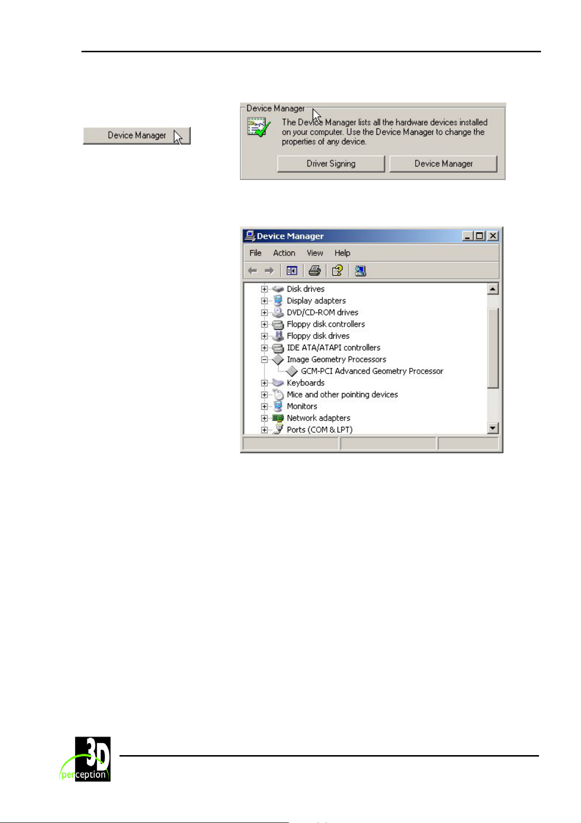
Step 5. Select the Device Manager
From within the Device
Manager area click on
Step 6. Select Image Geometry Processor
From the Device Manager list
open up the Image Geometry
Processors group and double
click the GCM-PCI Advanced
Geometry Processor
13
Page 18
3D Perception CompactUTM
Revision 6 User Manual
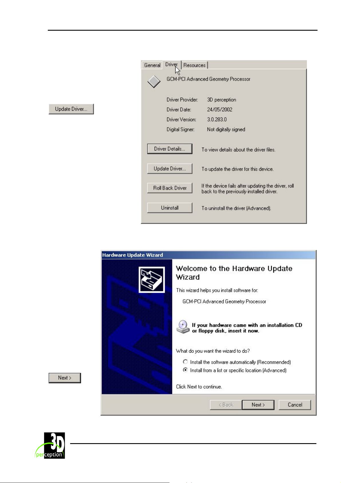
Step 7. Select Update Driver
From the Advanced Geometry
Processor Properties dialogue
box select the Driver page
and then click Update Driver
Step 8. Hardware Update Wizard
The Hardware
Update Wizard
will now begin.
On this first
page, under
‘What do want
the wizard to
do?’, be sure to
select Install
from a list or
specific
location
(Advanced)
Then click
to
proceed.
14
Page 19
3D Perception CompactUTM
Revision 6 User Manual
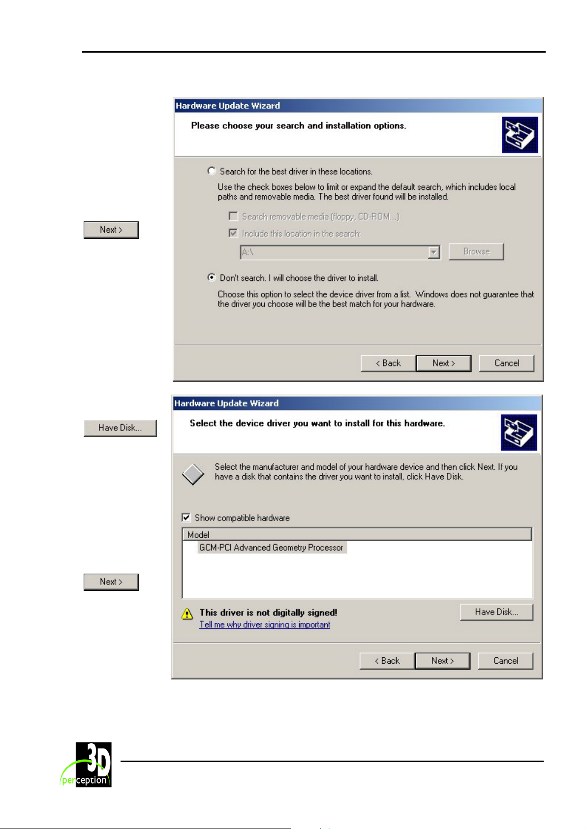
Select ‘Don’t
search. I will
choose the
driver to
install’.
Then click
to
proceed
Click
to select the
area where you
have the GCM
updates stored.
Either
downloaded
from the web or
held on a CDROM.
Click
15
Page 20
3D Perception CompactUTM
Revision 6 User Manual
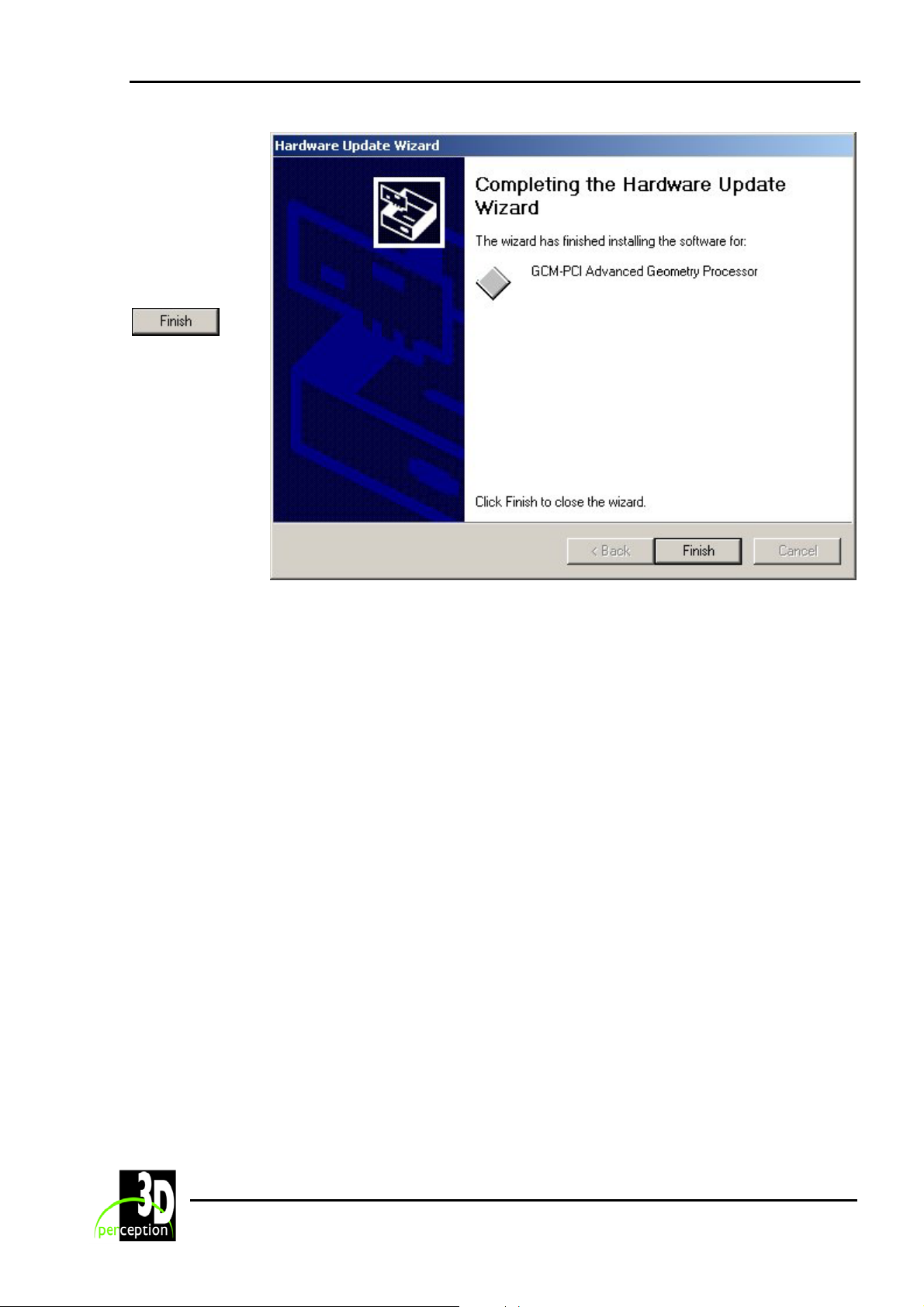
The GCM-PCI
Advanced
Geometry
Processor is
now complete.
Click
16
Page 21

3D Perception CompactUTM
Revision 6 User Manual
7. COMPACTCONTROL/COMPACTDESIGNER SOFTWARE
The CompactControl/CompactDesigner software may be installed either directly from a CDROM or by downloading from the Internet. CompactControl/CompactDesigner provides the user
with full geometry correction, edge control, gamma control and colour control.
For full details of the CompactControl/CompactDesigner software the reader should refer to the
CompactControl/CompactDesigner User Manual.
Note: To install or upgrade software on the CompactUTM, a keyboard, mouse and monitor
must be connected.
7.1 About CompactControl/CompactDesigner
CompactControl/CompactDesigner allows the user to set up a model of the actual theatre
option and to place projectors in the theatre model at the desired physical locations.
CompactControl/CompactDesigner then allows the user to perform geometry adjustment, edge
blending, gamma correction and colour balancing in order to create a continuous picture with
evenly distributed light intensity.
Projection theatre geometry is downloaded to the CompactUTM for easy calibration of
geometry, soft edges and hot spot compensation.
7.2 Installation
The CompactControl/CompactDesigner software is delivered on CD-ROM media, or may be
downloaded from the Internet. You may install the CompactControl/CompactDesigner software
onto a Lap Top (recommended) or directly onto the CompactUTM. See ‘Set-Up Scenarios’ for
full details.
Note: To control the CompactUTM, CompactControl/CompactDesigner version 3 or later is
required.
1. Installation from CD-ROM
Insert the CD. Depending on your computer’s set-up, the installation program may start
automatically.
If it does not, you need to locate the set-up program on the root
directory of the CD:
Double-click the icon to start the set-up procedure.
2. Installation from self-extracting executable
Locate the executable file and double-click its icon to start the set-up procedure. The installation
procedure will now guide you through the set-up process.
17
Page 22

3D Perception CompactUTM
Revision 6 User Manual
7.3 Software License
The set-up program requires you to enter a valid software license serial number.
The first time you run the set-up program, the serial number will be set to a dummy value:
CV0000-0-0000-00000000-00000000.
Use this default value to calculate the machine ID.
The serial number is based on a unique ID of the target computer. To obtain a full license, you
will need to run the set-up program once to calculate the ID, which must be sent to your
distributor for a license serial number to be generated.
When you have received the serial number for your machine, run the set-up program again.
The serial number must be entered exactly to allow set-up to continue.
The set-up program will not allow you to continue until a valid license serial number has been
entered.
You will now have CompactControl/CompactDesigner loaded on your PC.
18
Page 23

3D Perception CompactUTM
Revision 6 User Manual
8. PLUG AND PLAY DATA IN MONITORS
Plug and Play data for monitors is a data block present in most monitors. The computer (or
image generator) reads the Plug and Play data at start-up, thus allowing the computer to
prevent monitor settings, which are not supported by the monitor, from being set by the user.
Typically, a GCM card will be inserted between a computer and a projector and can be
considered a monitor itself. The standard scenario is that the GCM card reads the Plug and Play
data from the monitor; filters it and then passes it on to the computer. The reason for the filtering
process is to prevent the computer using monitor settings that are supported by the projector
but not supported by the GCM card.
19
Page 24
3D Perception CompactUTM
Revision 6 User Manual
9. SET-UP SCENARIOS
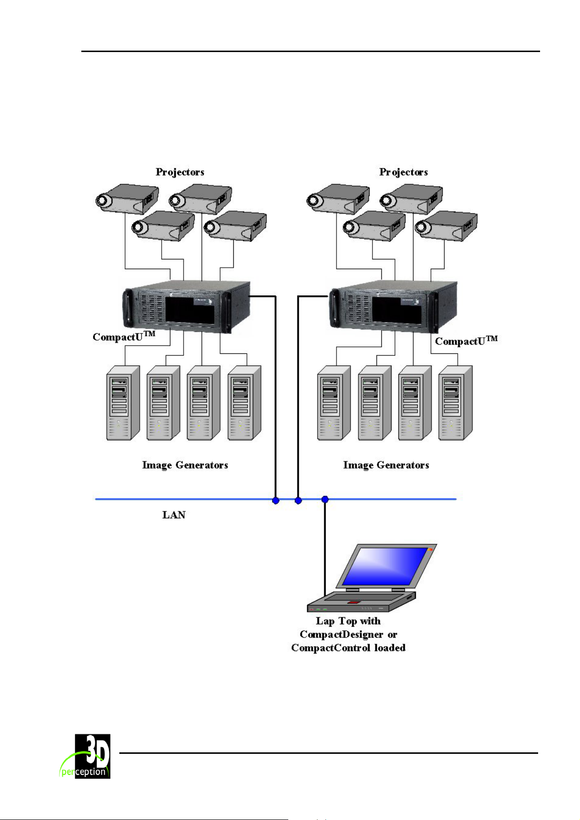
9.1 CompactControl/CompactDesigner in Laptop
NOTE: If the proposed system is for 4 or less channels, only one CompactUTM will be required
and then the laptop may be connected directly to the CompactUTM
.
20
Page 25
3D Perception CompactUTM
Revision 6 User Manual
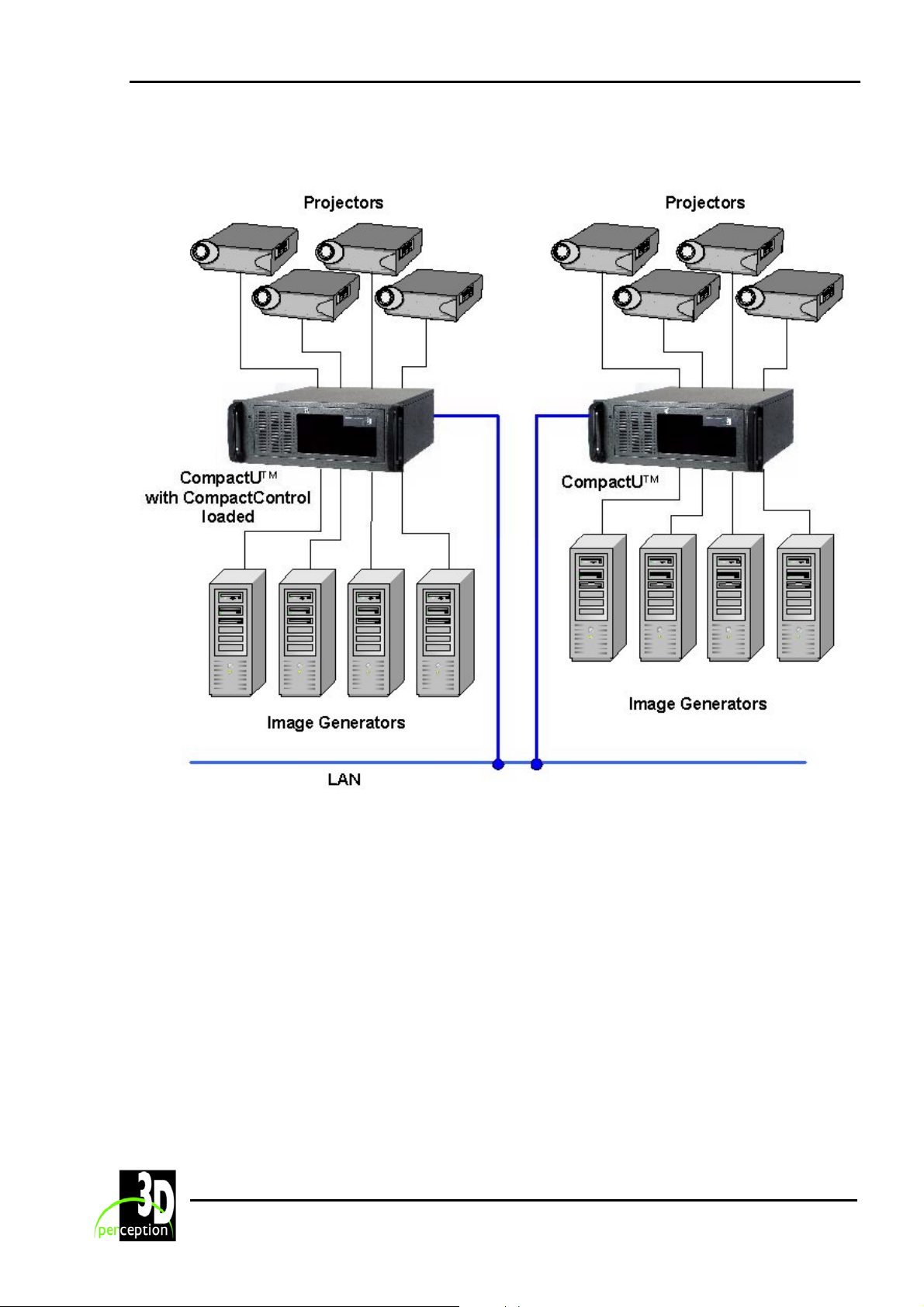
9.2 CompactControl/CompactDesigner in CompactUTM
21
Page 26
3D Perception CompactUTM
Revision 6 User Manual
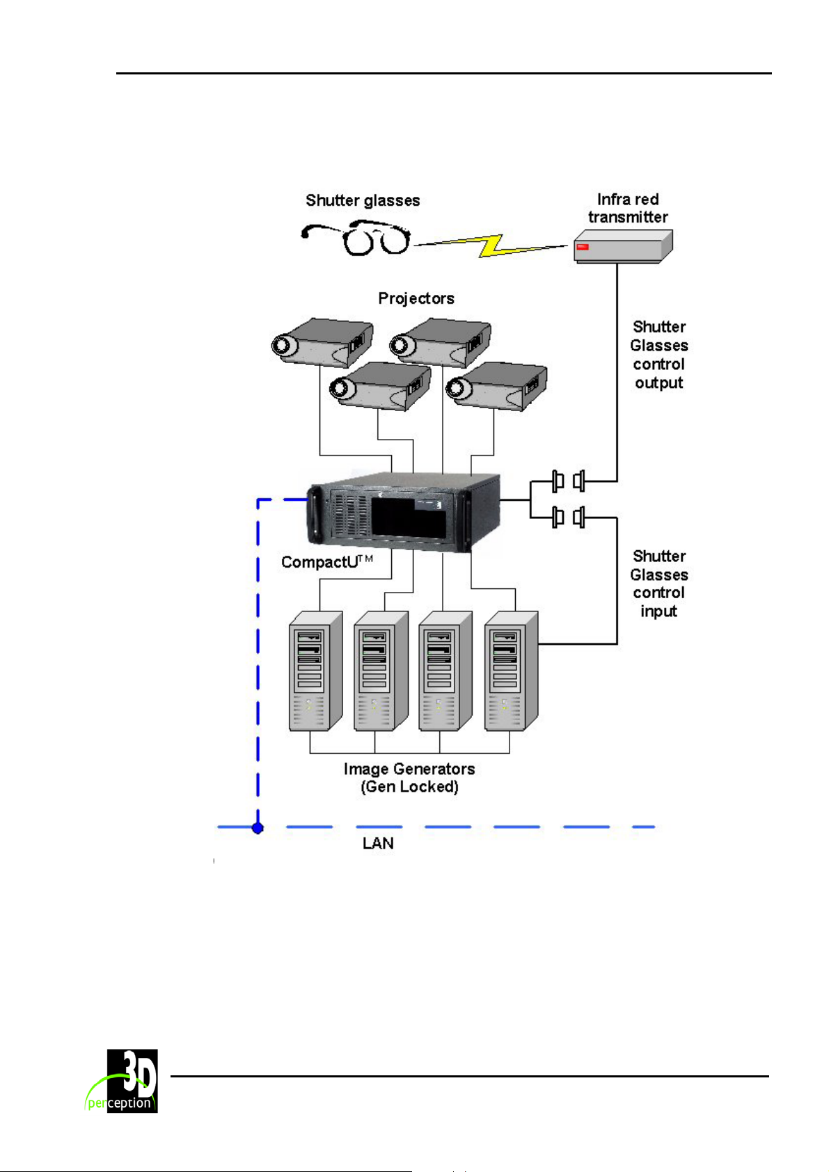
9.3 Typical System Scenario with Stereo
22
Page 27

3D Perception CompactUTM
Revision 6 User Manual
10. REGISTRY VARIABLES
Registry variables are held in the following registry location:
HKEY_LOCAL_MACHINE/SYSTEM/CurrentControlSet/Services/GCMPCIdr/Parameters
Registry variables are changed in the ‘regedit’ program. This program is started by selecting
‘Run’ in the ‘Start’ menu, and then typing ‘regedit’ in the Run window.
NOTE: It may take up to five seconds after a registry value has been changed before it is
actually read by the CompactUTM software.
Under normal circumstances registry variables should not require changing, they are listed here
for reference purposes only.
NOTE:
1 Changing registry variables may corrupt the signal set-up.
2 Changing one registry variable influence all the channels.
The following is a detailed list of all registry variables used by the CompactUTM.
ADC Bandgap Voltage
Purpose: Band gap voltage for the Analogue/Digital converter.
This variable is not used; it is kept for backward compatibility only.
Values: Range 0 - 7
7 = Default
ADC Clock Delay, Blue
Purpose: Clock delay for the blue channel in the Analogue/Digital converter.
This variable is not used; it is kept for backward compatibility only.
Values: Range 0 - 7
2 = Default
ADC Clock Delay, Green
Purpose: Clock delay for the green channel in the Analogue/Digital converter.
This variable is not used; it is kept for backward compatibility only.
Values: Range 0 - 7
2 = Default
ADC Clock Delay, Red
Purpose: Clock delay for the red channel in the Analogue/Digital converter.
This variable is not used; it is kept for backward compatibility only.
Values: Range 0 - 7
2 = Default
23
Page 28

3D Perception CompactUTM
Revision 6 User Manual
ADC Comparator Offset, Blue, Chan A
Purpose: Comparator offset for the blue channel in the Analogue/Digital converter.
Outgoing channel A.
This variable is not used; it is kept for backward compatibility only.
Values: Range 0 - 15
14 = Default
ADC Comparator Offset, Blue, Chan B
Purpose: Comparator offset for the blue channel in the Analogue/Digital converter.
Outgoing channel B.
This variable is not used; it is kept for backward compatibility only.
Values: Range 0 - 15
14 = Default
ADC Comparator Offset, Green, Chan A
Purpose: Comparator offset for the green channel in the Analogue/Digital converter.
Outgoing channel A.
This variable is not used; it is kept for backward compatibility only.
Values: Range 0 - 15
14 = Default
ADC Comparator Offset, Green, Chan B
Purpose: Comparator offset for the green channel in the Analogue/Digital converter.
Outgoing channel B.
This variable is not used; it is kept for backward compatibility only.
Values: Range 0 - 15
14 = Default
ADC Comparator Offset, Red, Chan A
Purpose: Comparator offset for the red channel in the Analogue/Digital converter.
Outgoing channel A.
This variable is not used; it is kept for backward compatibility only.
Values: Range 0 - 15
14 = Default
ADC Comparator Offset, Red, Chan B
Purpose: Comparator offset for the red channel in the Analogue/Digital converter.
Outgoing channel B.
This variable is not used; it is kept for backward compatibility only.
Values: Range 0 - 15
14 = Default
24
Page 29

3D Perception CompactUTM
Revision 6 User Manual
ADC Global Data Delay
Purpose: Global data delay for the data through the Analogue/Digital converter.
This variable is not used; it is kept for backward compatibility only.
Values: Range 0 - 7
5 = Default
ADC Ignore HSYNC during VSYNC
Purpose: Force HSYNC to be ignored by Analogue/Digital converter during the VSYNC
period.
Values: 153 = Default - Ignore this variable
0 = Never ignore HSYNC during VSYNC
1 = Always ignore HSYNC during VSYNC
ADC Ignore HSYNC during VSYNC automatically
Purpose: Force HSYNC to be ignored automatically by Analogue/Digital converter during the
VSYNC period.
Values: 153 = Default - Ignore this variable
0 = During auto set-up never ignore HSYNC during VSYNC
1 = During auto set-up always ignore HSYNC during VSYNC
ADC Invert VSYNC polarity
Purpose: Invert the VSYNC polarity in the Analogue/Digital converter.
This variable is not used; it is kept for backward compatibility only.
Values: 0 and 1
0 = Default
ADC Number of HSYNCS to ignore post VSYNC
Purpose: Set the number of HSYNC pulses that should be ignored before start of VSYNC.
Only applicable if HSYNC is ignored during VSYNC.
Values: Range 0 - 10
0 = Default
ADC Number of HSYNCS to ignore pre VSYNC
Purpose: Set the number of HSYNC pulses that should be ignored after end of VSYNC.
Only applicable if HSYNC is ignored during VSYNC.
Values: Range 0 - 10
0 = Default
ADC Sync Type
Purpose: Set the sync type of the incoming signal.
Values: 153 = Default - Ignore this variable
0 = Separate sync.
1 = Composite sync on HSYNC
2 = Composite sync on green
3 = Detect sync type automatically during auto set-up.
25
Page 30

3D Perception CompactUTM
Revision 6 User Manual
BreakOnEntry
Purpose: Internal use only.
Values: 0 and 1
1 = Default
DebugInfo
Purpose: Internal use only.
Values: 0 and 1
1 = Default
DVI TX clock de-skew
Purpose: Set the DVI clock de-skew in the DVI transmitter
Values: Range 0 - 7
2 = Default
Ignore Displays EDID (EDID data is part of the Plug and Play standard).
Purpose: Specifies how the EDID data of the projector connected to the UTM should be
treated.
Values: 0 = Default - Both internal EDID and the EDID read from the
projector/display to be sent to the image generator.
1 = Only the internal EDID to be sent to the image generator.
IgnoreRamTestResult
Purpose: Internal use only.
Values: 0 and 1
0 = Default
Internal state dump
Purpose: Write internal state dumps to monitor.
Values: 0 = Default - Do not write internal state dump
1 = Write internal state dump to monitor
LogApplicationEvents
Purpose: Log different application events.
Values: 0 = Default - Do not log any application events
1 = Log the application events to the event viewer
Offset, Blue, Even bus
Purpose: Adjust the blue offset on the Even bus to the graphics processor.
Values: Range -31 to +31
0 = Default
NOTE: Values must be entered in twos complement form.
26
Page 31

3D Perception CompactUTM
Revision 6 User Manual
Offset, Blue, Odd bus
Purpose: Adjust the blue offset on the Odd bus to the graphics processor.
Values: Range -31 to +31
0 = Default
NOTE: Values must be entered in twos complement form.
Offset, Green, Even bus
Purpose: Adjust the green offset on the Even bus to the graphics processor.
Values: Range -31 to +31
0 = Default
NOTE: Values must be entered in twos complement form.
Offset, Green, Odd bus
Purpose: Adjust the green offset on the Odd bus to the graphics processor.
Values: Range -31 to +31
0 = Default
NOTE: Values must be entered in twos complement form.
Offset, Red, Even bus
Purpose: Adjust the red offset on the Even bus to the graphics processor.
Values: Range -31 to +31
0 = Default
NOTE: Values must be entered in twos complement form.
Offset, Red, Odd bus
Purpose: Adjust the red offset on the Odd bus to the graphics processor.
Values: Range -31 to +31
0 = Default
NOTE: Values must be entered in twos complement form.
Output Latency [lines]
Purpose: Set the latency time in lines, i.e., number of lines the output signal is delayed
compared to the input signal.
Values: Range 0 - 511
250 = Default
The actual latency time (in milliseconds) may be found by the
following formula: Output latency lines/Horizontal frequency in kHz
NOTE: The geometry correction may be corrupted if this value is
amended.
27
Page 32

3D Perception CompactUTM
Revision 6 User Manual
11. MAINTENANCE
All maintenance should be done by 3D Perception authorised service personnel. Contact
your 3D Perception Value Added Reseller for maintenance.
28
Page 33

3D Perception CompactUTM
Revision 6 User Manual
12. LIMITED WARRANTY, ‘FCC STATEMENT’ AND
‘TRADEMARKS COPYRIGHT’
Limited Warranty
Except as otherwise stated herein, 3D Perception warrants to the first end-user (‘Customer’)
who purchases a CompactUTM from a Value Added Reseller that the CompactUTM is free from
defects in parts and labour under normal use during the warranty period. The warranty period
means the 12-month period from the date of the Customer’s purchase of the CompactUTM from
a Value Added Reseller.
During the warranty period, 3D Perception will, at its option and in its sole discretion, repair or
replace defective parts, including replacement of the entire CompactUTM, at no additional
charge to the Customer. However, the Customer is responsible for all shipping and insurance
costs incurred in returning any CompactUTM to the Customer which does not require any repair
or replacement work, as determined by 3D Perception in its sole discretion. This limited
warranty does not extend to any 3D Perception product that has been damaged as a result of
accident, misuse, or abuse. Nor does it extend to the use of parts not manufactured or sold by
3D Perception, by unauthorised modification of the CompactUTM, or as a result of servicing by
unauthorised personnel. This limited warranty extends only to the Customer, and is not
transferable or applicable to any other third party or user, including any one who purchases a
used CompactUTM. Any person asserting a claim under this limited warranty must establish to
3D Perception’ satisfaction the date of purchase and that the CompactUTM was purchased
new.
Other warranty and liability limitations
Aside from this standard published warranty, 3D Perception makes no warranty of any kind,
express or implied, including without limitation, those of merchantability and of fitness for a
particular purpose. Without limiting the generality of the foregoing, any description of the
CompactUTM is for the sole purpose of identifying it, is not part of the basis of any bargain, and
does not constitute a warranty that the item sold shall conform to that description. The use of
any sample or model is for illustrative purposes only, it is not part of the basis of any bargain,
and it is not to be construed as a warranty that the CompactUTM will conform to the sample or
model.
No affirmation of fact or promise made by 3D Perception shall constitute a warranty that the
CompactUTM will conform to the affirmation or promise. 3D Perception makes no warranty that
the goods are free from claims of infringement of patents, trademarks, or copyrights. This limited
warranty shall be the exclusive remedy. 3D Perception shall not be liable to customers or others
for incidental, consequential, or special damages, or lost profits. Under no circumstance shall
3D Perception liability or customer’s remedy for damages against 3D Perception exceed its cost
for the CompactUTM.
29
Page 34

3D Perception CompactUTM
Revision 6 User Manual
Procedure for claims
Any and all questions or claims concerning the CompactUTM shall be made to 3D Perception
authorised personnel. In no case shall the CompactUTM be returned without first securing the
authority of 3D Perception or its authorised personnel. Any damages to, defects in, loss of, non
conformities in, or any other claim concerning the CompactUTM which could be discovered by
inspection upon delivery must be reported to the delivering carrier, and in writing to 3D
Perception at: the following address, promptly and in no event later than thirty (30) days after
delivery.
3D Perception AS
Solbråveien 41
P.O. Box 455
N-1373 Asker
Norway
In the case of any such claim, inspection shall be promptly arranged with 3D Perception or it’s
authorised personnel, and where appropriate, representatives of the carrier. Any other claim or
action respecting the condition or conformity of the CompactUTM or any other matter affecting
the CompactUTM must be submitted in writing to 3D Perception promptly upon discovery and in
no event later than expiration of the Warranty Period. Any part of the CompactUTM which is
subject of any claim shall be set aside and protected, without further processing or use, until 3D
Perception or its authorised personnel have an opportunity to inspect it and advice the
Customer of the disposition, if any to be made thereof. Failure to give timely written notice of
any claim shall bar any remedy.
Technical advice
3D Perception, or its authorised personnel, may furnish technical advice with reference to the
use of the CompactUTM, but there is no obligation to furnish such advice. If any advice or
assistance is furnished, it shall be given and accepted at Customer’s risk, 3D Perception shall
not be responsible or liable for the advice or assistance given or the results thereof.
FCC Statement
The CompactUTM has been tested and found to comply with the limits for a 'Class A' digital
device, pursuant to Part 15 of the FCC rules. These limits are designed to provide reasonable
protection against harmful interference when it is operated in a commercial environment. The
CompactUTM generates, uses and can radiate radio frequency energy and, if not used in
accordance with the instruction manual, may cause harmful interference to radio
communications. Operation of the CompactUTM in a residential area is likely to cause harmful
interference in which case the user will be required to correct the interference at own expense.
Trademarks Copyright
3D P
ERCEPTION IS A REGISTERED TRADEMARK. OTHER TRADEMARKS ARE THE PROPERTY OF THEIR
RESPECTIVE OWNERS
. NORWEGIAN AND FOREIGN PATENTS ARE PENDING.
30
Page 35

3D Perception CompactUTM
Revision 6 User Manual
13. CONTACT US
3D PERCEPTION AS
Solbråveien 41
P. O. Box 455
N1373 Asker, Norway
Tel: +47 66 98 70 70
Fax: +47 66 98 70 71
Web site www.3d-perception.com
31
 Loading...