


|
SuperStack® II Switch 1100 |
® |
User Guide |
|
3C16950, 3C16951
http://www.3com.com/
Part No. DUA1695-0AAA04
Published April 1999

3Com Corporation 5400 Bayfront Plaza Santa Clara, California 95052-8145
Copyright © 1999, 3Com Technologies. All rights reserved. No part of this documentation may be reproduced in any form or by any means or used to make any derivative work (such as translation, transformation, or adaptation) without written permission from 3Com Technologies.
3Com Technologies reserves the right to revise this documentation and to make changes in content from time to time without obligation on the part of 3Com Technologies to provide notification of such revision or change.
3Com Technologies provides this documentation without warranty, term, or condition of any kind, either implied or expressed, including, but not limited to, the implied warranties, terms or conditions of merchantability, satisfactory quality, and fitness for a particular purpose. 3Com may make improvements or changes in the product(s) and/or the program(s) described in this documentation at any time.
If there is any software on removable media described in this documentation, it is furnished under a license agreement included with the product as a separate document, in the hard copy documentation, or on the removable media in a directory file named LICENSE.TXT or !LICENSE.TXT. If you are unable to locate a copy, please contact 3Com and a copy will be provided to you.
UNITED STATES GOVERNMENT LEGEND
If you are a United States government agency, then this documentation and the software described herein are provided to you subject to the following:
All technical data and computer software are commercial in nature and developed solely at private expense. Software is delivered as “Commercial Computer Software” as defined in DFARS 252.227-7014 (June 1995) or as a “commercial item” as defined in FAR 2.101(a) and as such is provided with only such rights as are provided in 3Com’s standard commercial license for the Software. Technical data is provided with limited rights only as provided in DFAR 252.227-7015 (Nov 1995) or FAR 52.227-14 (June 1987), whichever is applicable. You agree not to remove or deface any portion of any legend provided on any licensed program or documentation contained in, or delivered to you in conjunction with, this User Guide.
Unless otherwise indicated, 3Com registered trademarks are registered in the United States and may or may not be registered in other countries.
3Com, the 3Com logo, Net Age, SmartAgent, SuperStack and Transcend are registered trademarks of
3Com Corporation. CoreBuilder and PACE are trademarks of 3Com Corporation. 3ComFacts is a service mark of 3Com Corporation.
All other company and product names may be trademarks of the respective companies with which they are associated.
Environmental Statement
It is a 3Com policy to be environmentally friendly in all operations. This manual is printed on paper that comes from sustainable, managed European forests. The production process for making the pulp has a reduced AOX level (adsorbable organic halogen) resulting in elemental chlorine-free paper.
The paper is fully biodegradable and recyclable.

CONTENTS
ABOUT THIS GUIDE
|
Conventions 8 |
|
|
|
|
|
|
Related Documentation |
9 |
|
|
|
|
|
Year 2000 Compliance |
10 |
|
|
|
|
|
Documentation Comments |
10 |
|
|
||
|
|
|||||
1 INTRODUCING THE SWITCH 1100 |
||||||
|
About the SuperStack II Switch 1100 |
12 |
||||
|
Summary of Features |
12 |
|
|
||
|
Switch 1100 — Front View Detail |
13 |
||||
|
Port Connections 13 |
|
|
|
||
|
LEDs 14 |
|
|
|
|
|
|
Switch 1100 — Rear View Detail |
15 |
|
|||
|
Unit Information Label |
15 |
|
|
||
|
Power Socket |
15 |
|
|
|
|
|
Redundant Power System Socket |
15 |
||||
|
Console Port |
15 |
|
|
|
|
|
Expansion Module Slot |
16 |
|
|
||
|
Transceiver Module Slot |
16 |
|
|
||
|
Matrix Port |
16 |
|
|
|
|
|
Network Configuration Examples |
17 |
|
|||
|
Network Segmentation I |
17 |
|
|
||
|
Network Segmentation II |
18 |
|
|
||
|
Desktop Switching |
19 |
|
|
|
|
|
Configuration Rules for Fast Ethernet |
20 |
||||
|
Configuration Rules with Full Duplex |
21 |
||||
|
|
|
|
|||
2 INSTALLING THE SWITCH |
|
|
||||
|
Choosing a Suitable Site |
24 |
|
|
||
|
Rack-mounting |
24 |
|
|
|
|

|
Placing Units On Top of Each Other |
25 |
||||
|
Stacking Units |
26 |
|
|
|
|
|
Stacking Two Units |
26 |
|
|
||
|
Stacking Up To Four Units |
27 |
|
|||
|
The Power-up Sequence |
29 |
|
|
||
|
Connecting a Redundant Power System 29 |
|||||
|
Powering-up the Switch 1100 |
29 |
||||
|
Checking for Correct Operation |
29 |
||||
|
Choosing the Correct Cables |
30 |
|
|||
|
Solving Problems Indicated by LEDs |
31 |
||||
|
Managing the Switch |
|
32 |
|
|
|
A |
|
|
|
|||
SAFETY INFORMATION |
|
|
||||
|
Important Safety Information |
34 |
|
|||
|
L’information de Sécurité Importante 36 |
|||||
|
Wichtige Sicherheitsinformationen |
38 |
||||
B |
|
|
|
|
|
|
PIN-OUTS |
|
|
|
|
|
|
|
Null Modem Cable |
39 |
|
|
|
|
|
PC-AT Serial Cable |
39 |
|
|
|
|
|
Modem Cable |
40 |
|
|
|
|
|
RJ45 Pin Assignments |
|
40 |
|
|
|
CTECHNICAL SPECIFICATIONS
DTECHNICAL SUPPORT
Online Technical Services |
43 |
|
|
|
World Wide Web Site |
43 |
|
|
|
3Com Knowledgebase Web Services |
43 |
|||
3Com FTP Site |
44 |
|
|
|
3Com Bulletin Board Service |
44 |
|
||
3Com Facts Automated Fax Service |
45 |
|||
Support from Your Network Supplier |
45 |
|||
Support from 3Com |
45 |
|
|
|
Returning Products for Repair |
47 |
|
||
iv

GLOSSARY
INDEX
3COM CORPORATION LIMITED WARRANTY
EMC STATEMENTS
v

vi

ABOUT THIS GUIDE
This guide provides all the information you need to install and use a SuperStack® II Switch 1100 unit with default settings. If you want to change the way the Switch works using management software, refer to the “SuperStack II Switch Management Guide” (part number DUA1695-0BAA0x).
The guide is intended for use by network administrators who are responsible for installing and setting up network equipment; consequently, it assumes a basic working knowledge of LANs (Local Area Networks).
This guide is intended for use with both Switch 1100 models:
■3C16950 — 24 10BASE-T ports
■3C16951 — 12 10BASE-T ports
All pictures and example screens show the 24-port model, however, all procedures apply to the 24-port model and the 12-port model.
If the information in the release notes that are shipped with your product differs from the information in this guide, follow the instructions in the release notes.
Most user guides and release notes are available in Adobe Acrobat Reader Portable Document Format (PDF) or HTML on the 3Com World Wide Web site:
http://www.3com.com/
8 ABOUT THIS GUIDE
Conventions |
Table 1 and Table 2 list conventions that are used throughout this guide. |
||
|
Table 1 |
Notice Icons |
|
|
|
|
|
|
Icon |
Notice Type |
Description |
|
|
|
|
|
|
Information note Information that describes important features or |
|
|
|
|
instructions |
|
|
Caution |
Information that alerts you to potential loss of data or |
|
|
|
potential damage to an application, system, or device |
|
|
Warning |
Information that alerts you to potential personal injury |
|
|
|
|
|
Table 2 |
Text Conventions |
|
|
|
|
|
|
Convention |
Description |
|
|
|
|
|
|
Screen displays |
This typeface represents information as it appears on the |
|
|
|
|
screen. |
|
|
|
|
|
Syntax |
|
The word “syntax” means that you must evaluate the syntax |
|
|
|
provided and then supply the appropriate values for the |
|
|
|
placeholders that appear in angle brackets. Example: |
|
|
|
To enable RIPIP, use the following syntax: |
|
|
|
SETDefault !<port> -RIPIP CONTrol = |
|
|
|
Listen |
|
|
|
In this example, you must supply a port number for <port>. |
|
|
|
|
|
Commands |
The word “command” means that you must enter the |
|
|
|
|
command exactly as shown and then press Return or Enter. |
|
|
|
Commands appear in bold. Example: |
|
|
|
To remove the IP address, enter the following command: |
|
|
|
SETDefault !0 -IP NETaddr = 0.0.0.0 |
|
|
|
|
|
The words “enter” |
When you see the word “enter” in this guide, you must type |
|
|
and “type” |
something, and then press Return or Enter. Do not press |
|
|
|
|
Return or Enter when an instruction simply says “type.” |
|
|
|
|
|
Keyboard key names |
If you must press two or more keys simultaneously, the key |
|
|
|
|
names are linked with a plus sign (+). Example: |
Press Ctrl+Alt+Del

Related Documentation |
9 |
Table 2 Text Conventions (continued)
Convention |
Description |
|
|
Words in italics |
Italics are used to: |
|
■ Emphasize a point. |
|
■ Denote a new term at the place where it is defined in the |
|
text. |
|
■ Identify menu names, menu commands, and software |
|
button names. Examples: |
|
From the Help menu, select Contents. |
|
Click OK. |
|
|
Related |
In addition to this guide, each Switch 1100 document set includes the |
Documentation |
following: |
|
■ Management Guide (Part Number DUA1695-0BAA0x) |
|
This guide contains all the management information for the Switch. |
|
■ Quick Reference Guide (Part Number DQA1695-0AAA0x) |
|
This guide contains a quick summary of the hardware and software |
|
information for the Switch |
|
■ Quick Installation Guide (Part Number DIA1695-0AAA0x) |
|
This guide contains a summary of the package contents, and a quick |
|
summary of the installation information for the Switch. |
|
■ Release Notes (Part Number DNA1695-0AAA0x) |
|
These notes provide information about the current software release, |
|
including new features, modifications, and known problems. |
|
■ SuperStack II Switch Help |
|
This help provides information about the web interface software of |
|
the Switch. It is supplied on the SuperStack II Switch CD-ROM. |
|
■ SuperStack II Switch README File |
|
This file provides information about the current software release, |
|
including new features, modifications, and known problems. |

10 ABOUT THIS GUIDE
|
In addition, there are other publications you may find useful: |
|
■ Documentation accompanying the Expansion Modules. |
|
■ Documentation accompanying the Transceiver Modules. |
|
■ Documentation accompanying the Advanced Redundant Power |
|
System. |
|
|
Year 2000 |
For information on Year 2000 compliance and 3Com products, visit the |
Compliance |
3Com Year 2000 Web page: |
|
http://www.3com.com/products/yr2000.html |
|
|
Documentation |
Your suggestions are very important to us. They will help make our |
Comments |
documentation more useful to you. Please e-mail comments about this |
|
document to 3Com at: |
|
pddtechpubs_comments@3com.com |
|
Please include the following information when commenting: |
|
■ Document title |
|
■ Document part number (on the title page) |
|
■ Page number (if appropriate) |
Example:
■SuperStack II Switch 1100 User Guide
■Part Number DUA1695-0AAA03
■Page 21
INTRODUCING THE SWITCH 1100
1
This chapter contains introductory information about the Switch and how it can be used in your network. It covers the following topics:
■About the SuperStack II Switch 1100
■Switch 1100 — Front View Detail
■Switch 1100 — Rear View Detail
■Network Configuration Examples
■Configuration Rules for Fast Ethernet
■Configuration Rules with Full Duplex
12 CHAPTER 1: INTRODUCING THE SWITCH 1100
About the |
The SuperStack® II system solves the problem of growth in dynamic |
SuperStack II |
network environments and provides everything you need for successful |
Switch 1100 |
workgroup networking. Much more than a collection of stackable |
|
components, the system comprises a complete, integrated architecture of |
|
modular parts that are easy to install and use. |
|
As part of this SuperStack II system, the Switch 1100 meets the challenge |
|
of modern LANs and allows you to add features and capacity as your |
|
network expands. |
Summary of Features The Switch has the following hardware features:
■12 or 24 Ethernet 10BASE-T ports
■Two Fast Ethernet auto-negotiating 10BASE-T/100BASE-TX ports
■Matrix port for connecting units in the Switch 1100/3300 family to form a stack:
■Connect two units back-to-back using a single Matrix Cable
■Connect up to four units using Matrix Cables linked to a Matrix Module
■Slot for an Expansion Module
■Slot for a Transceiver Module (10Mbps Ethernet)
■SuperStack II architecture:
■Connects to Redundant Power System / Uninterruptible Power System
■19-inch rack or stand-alone mounting
For information about the software features of the Switch, refer to the “SuperStack II Switch Management Guide” (DUA1695-0BAA0x).
Switch 1100 — Front View Detail 13
Switch 1100 —
Front View Detail
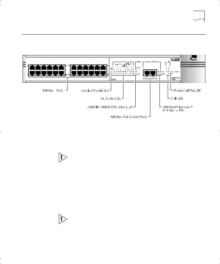
Figure 1 Switch 1100 — Front view
Port Connections 10BASE-T Ports
The Switch has 12 or 24 10BASE-T ports configured as MDIX (cross-over). The maximum segment length is 100m (328ft) over Category 3, 4, or 5 twisted pair cable.
As these ports are configured as MDIX (cross-over), you need to use a cross-over cable to connect to devices whose ports are MDIX-only. See “Choosing the Correct Cables” on page 30 for more information.
10BASE-T/100BASE-TX Ports
The Switch has two auto-negotiating 10BASE-T/100BASE-TX ports configured as MDIX (cross-over). These ports can be set to 10BASE-T half duplex, 10BASE-T full duplex, 100BASE-TX half duplex, 100BASE-TX full duplex, or they can automatically detect the speed and duplex mode of a link and provide the appropriate connection. The maximum segment length is 100m (328ft) over Category 5 twisted pair cable.
As these ports are configured as MDIX (cross-over), you need to use a cross-over cable to connect to devices whose ports are MDIX-only. See “Choosing the Correct Cables” on page 30 for more information.

14 CHAPTER 1: INTRODUCING THE SWITCH 1100
LEDs Table 3 lists the LEDs visible on the front of the Switch, and their states according to color. For information on using the LEDs for problem solving, see “Checking for Correct Operation” on page 29.
Table 3 |
LED behavior |
|
|
|
|
LED |
Color |
Indicates |
|
|
|
TCVR |
Yellow |
Port 1 is a Transceiver Module fitted to the rear of the |
|
|
Switch. |
|
Off |
Port 1 is operating as a 10BASE-T port. |
Port Status LEDs |
|
|
Packet |
Yellow |
Packets are being transmitted/received on the port. |
|
Off |
No packets are being transmitted/received on the port. |
Status |
Green |
A link is present, and the port is enabled. |
|
Green flashing |
A link is present, but the port is disabled. |
|
Off |
No link is present. |
Expansion Module Port Status LEDs |
||
Packet |
Yellow |
Packets are being transmitted/received on the |
|
|
Expansion Module port(s). |
|
Off |
No packets are being transmitted/received on the |
|
|
Expansion Module port(s). |
Status |
Yellow |
A valid Expansion Module is installed. |
|
Yellow flashing |
An unrecognized Expansion Module is installed. |
|
Off |
No Expansion Module is installed. |
Unit LEDs |
|
|
1–8 |
Green |
The Switch forms a stack with other Switch units; the |
|
|
LED indicates the position of the Switch in the stack |
|
|
and that a link is present. Note that although there are |
|
|
eight LEDs, only four Switch units can be stacked at |
|
|
present. |
|
Off |
The Switch is stand-alone. |
Power/Self Test LED |
|
|
|
Green |
The Switch is powered-up. |
|
Green flashing |
The Switch is either downloading software or is |
|
|
initializing (which includes running a Power On Self |
|
|
Test). |
|
Yellow |
The Switch has failed its Power On Self Test. |
|
Off |
The Switch is not receiving power. |
|
|
|
Switch 1100 — Rear View Detail 15
Switch 1100 — Rear
View Detail
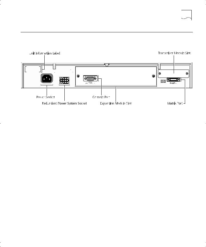
Figure 2 Switch 1100 — Rear view
Unit Information This label shows the following:
Label |
The 3Com product name of the Switch |
■ |
■The 3Com 3C number of the Switch
■The unique MAC address (Ethernet address) of the Switch
■The serial number of the Switch
You may need this information for fault reporting purposes.
Power Socket The Switch automatically adjusts its power setting to any supply voltage in the range 90–240V A.C.
Redundant Power To protect against internal power supply failure, you can use this socket System Socket to connect a SuperStack II Advanced Redundant Power System (RPS) to the Switch. See “Connecting a Redundant Power System” on page 29.
Console Port The console port allows you to connect a terminal and perform remote or local out-of-band management. The console port uses standard null modem cable and is set to auto-baud, 8 data bits, no parity and 1 stop bit.

16 CHAPTER 1: INTRODUCING THE SWITCH 1100
Expansion Module You can use this slot to install an Expansion Module; for example, a Slot 100BASE-FX Module that provides an additional high-speed link, or a
Matrix Module that provides four matrix ports for stacking Switch units together. 3Com provides a range of Expansion Modules; contact your supplier for availability. For more information about Matrix Modules, see “Stacking Units” on page 26.
When an Expansion Module is not installed, ensure the blanking plate is secured in place.
Transceiver Module You can use this slot to install a Transceiver Module. When a Transceiver Slot Module is installed, the Transceiver Module port becomes port 1 and the
port labelled 1 on the front panel becomes inactive. The Transceiver Module can provide a 10Mbps Ethernet half duplex link to the rest of your network using various media such as fiber and coaxial cabling.
When a Transceiver Module is not installed, ensure the blanking plate is secured in place.
Matrix Port The matrix port allows you to:
■Stack the Switch with another unit in the Switch 1100/3300 family using a single Matrix Cable
■Stack the Switch with up to three other units in the Switch 1100/3300 family, if one of the units has a Matrix Module installed
For more information about the role of the matrix port, see “Stacking
Units” on page 26.
Network Configuration Examples |
17 |
Network |
The following illustrations show some examples of how the Switch can be |
||||||||||||||||
Configuration |
placed on your network. |
||||||||||||||||
Examples |
|
|
|
|
|
|
|
|
|
|
|
|
|
|
|
|
|
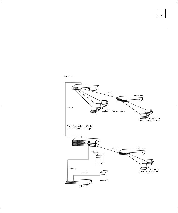
Network |
Figure 3 shows how the Switch 1100 fits into a large corporate network |
||||||||||||||||
Segmentation I |
with a Fast Ethernet infrastructure. A Switch is positioned on each floor |
||||||||||||||||
|
and servers are centralized in the basement. |
||||||||||||||||
|
Figure 3 Using the Switch 1100 to segment your network |
||||||||||||||||
|
|
|
|
|
|
|
|
|
|
|
|
|
|
|
|
|
|
|
|
|
|
|
|
|
|
|
|
|
|
|
|
|
|
|
|
|
|
|
|
|
|
|
|
|
|
|
|
|
|
|
|
|
|
|
|
|
|
|
|
|
|
|
|
|
|
|
|
|
|
|
|
|
|
|
|
|
|
|
|
|
|
|
|
|
|
|
|
|
|
|
|
|
|
|
|
|
|
|
|
|
|
|
|
|
|
|
|
|
|
|
|
|
|
|
|
|
|
|
|
|
|
|
|
|
|
|
|
|
|
|
|
|
|
|
|
|
|
|
|
|
|
|
|
|
|
|
|
|
|
|
|
|
|
|
|
|
|
|
|
|
|
|
|
|
|
|
|
|
|
|
|
|
|
|
|
|
|
|
|
|
|
|
|
|
|
|
|
|
|
|
|
|
|
|
|
|
|
|
|
|
|
|
|
|
|
|
|
|
|
|
|
|
|
|
|
|
|
|
|
|
|
|
|
|
|
|
|
|
|
|
|
|
|
|
|
|
|
|
|
|
|
|
|
|
|
|
|
|
|
|
|
|
|
|
|
|
|
|
|
|
|
|
|
|
|
|
|
|
|
|
|
|
|
|
|
|
|
|
|
|
|
|
|
|
|
|
|
|
|
|
|
|
|
|
|
|
|
|
|
|
|
|
|
|
|
|
|
|
|
|
|
|
|
|
|
|
|
|
|
|
|
|
|
|
|
|
|
|
|
|
|
|
|
|
|
|
|
|
|
|
|

18 CHAPTER 1: INTRODUCING THE SWITCH 1100
Network Figure 4 shows the Switch 1100 in a second workgroup situation. This Segmentation II setup could be that of a small office within a large corporation, or part of
a larger corporate network. Most of the switch ports have multiple endstations.
Figure 4 Using the Switch 1100 to segment your network
 Loading...