

Page 1
3B SCIENTIFIC® PHYSICS
U15310 Wimshurst Machine
Instruction Sheet
9/03 ALF
®
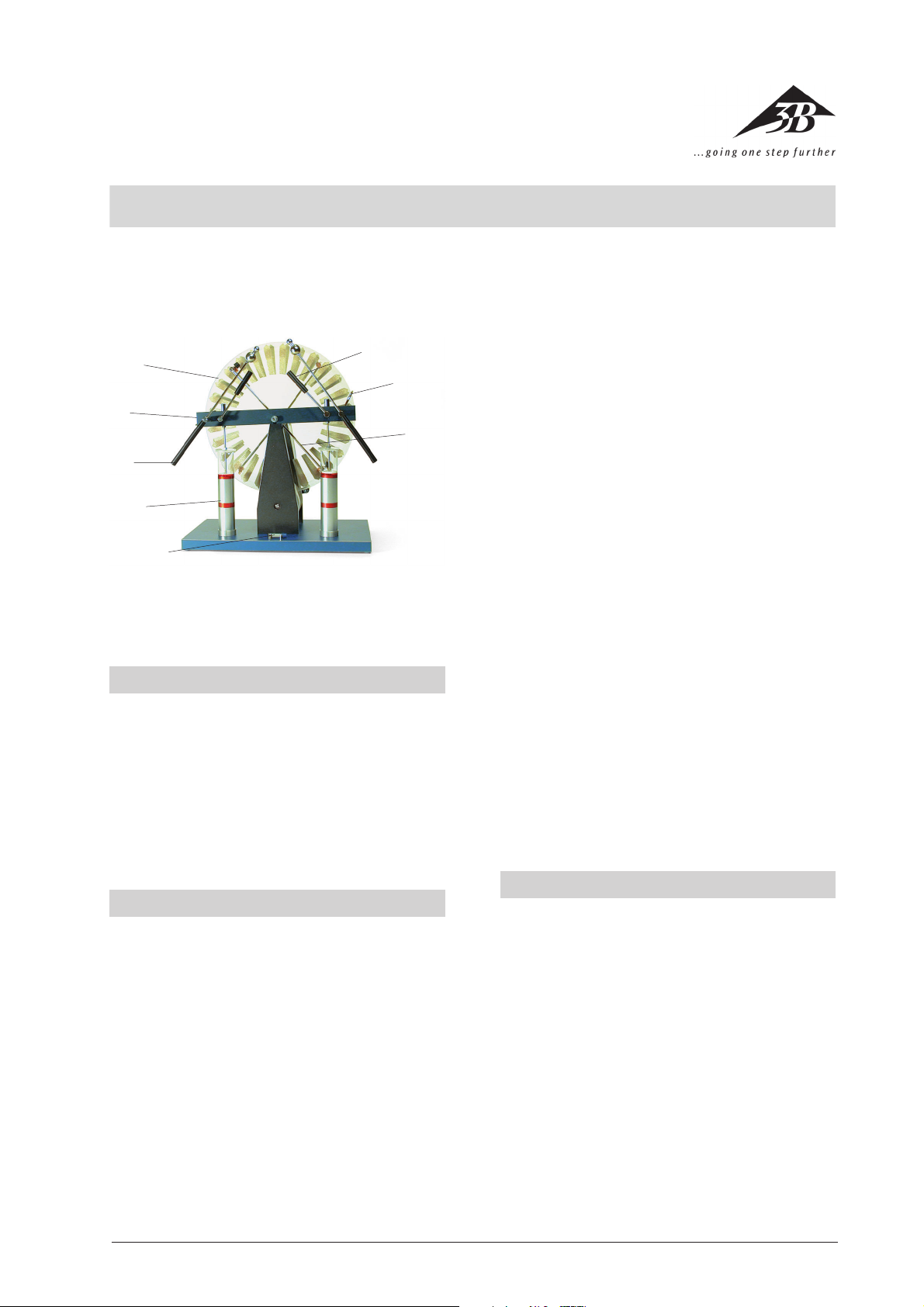
1
8
7
2
6
3
4
5
The Wimshurst machine serves as a source of safe, high
DC potentials for numerous experiments in the area of
electrostatics.
1. Safety instructions
• Caution! Sensitive electronic equipment (computers,
calculators, digital measuring instruments etc) can be
damaged by high-frequency interference peaks,
caused by voltage flashovers.
• Use only naphtha to clean the plastic parts. Never use
solvents for cleaning.
• Store your Wimshurst machine in a dry, dust free place.
Do not expose it to direct heat sources (sunlight, radiator).
1Transparent acrylic discs with tin-foil segments
2Insulating bar
3Electrode rods
4Leyden jars
5Isolating switch
6Diagonal rod with metal brushes
7Rod with combs
8Switch levers to connect the Leyden jars
and the combs
7on either end to draw off the electric charge. The dis-
tance from the discs is adjustable and should be a few
millimeters. They are connected to the electrode bars
3. The electrode bars end in double spheres, between
which the the arc-over occurs. The Leyden jars 4 (high-
voltage capacitors) can be hooked up to the electrode
bars by means of switch levers 8. The isolating switch
5can be thrown to connect the Leyden jars.
Diameter: 310 mm
Spark gap: max. 120 mm
Dimensions: 360 mm x 290 mm x 450 mm
Short circuit current: approx. 30 µA
Weight: 3.4 kg
2. Description, technical data
The Wimshurst machine is made up of two equally large,
parallel transparent acrylic discs 1 which are fitted on a
horizontal axle and slightly spaced from each other. The
axle rests on two wooden pillars mounted on a base
plate.
The Wimshurst machine is operated by hand crank with
both discs separately connected to the drive shaft by
means of two belts and two belt pulleys. One belt is
twisted, so that the discs rotate in opposite directions
when the hand crank is turned.
Tin-foil segments are placed around the circumference
of the outer surfaces of the discs. In front of each disc a
diagonal rod 6with two metal brushes is pivoted on
the axle with brushes sliding over the tin-foil segments.
Connected to the axle is a horizontal insulating bar 2 in
front of the Wimshurst machine with a rod holding combs
3. Operating principle
During operation an initial small charge is steadily increased by induction processes until the max. operating
voltage is obtained. The operating voltage is limited by
arc-over, drawing of current and insulation resistance.
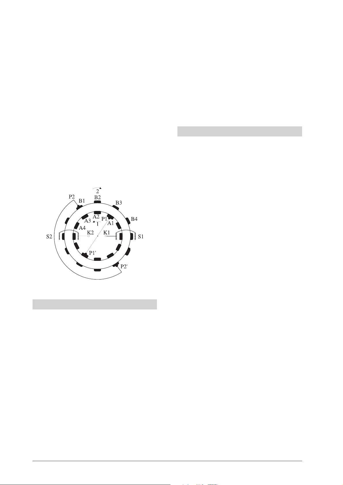
In order to make it easier to understand of the functioning principle of the Wimshurst machine, we imagine the
discs to be hollow cylinders which rotate around a common axle in opposite directions (cf. illustration).
When the tin-foil segment B1 has been charged positively by friction with the brush P2, it will move successively to positions B2 and B3. In position B3 it will be
opposite segment A1 which is connected to earth via
brush P1 and charged negatively. A1 will retain its negative charge when it moves to positions A2 and A3.
In position A3 it will charge segment B1 positively by
means of electric induction.
This process repeats itself constantly which leads to a
3
Page 2
steady increase of the electrical charge on the tin-foil
segments.
With further rotation all positively charged segments B
arrive at comb S1 and all negatively charged segments A
at comb S2 where all electric charge will be yielded to the
electrode rods with their conductor spheres K1 and K2.
The same processes happen in the lower part of the illustration with the difference that the tin-foil segments A
which pass brush P1’ are now charged positively and the
segments B passing P2’ negatively. The yielded voltage is
dependent on the diameter of the discs.
As a matter of fact the processes described here as a
sequence happen simultaneously.
On the tin-foil segments on disc 1 negative resp. positive
charges are induced below the brushes under the influence of the charges on disc 2. Those in turn induce electric charges on disc 2 when they pass the corresponding
brushes. The combs will remove all charges and yield
them to the electrode rods for arc-over between the conductor spheres or to the Leyden jars. The arc-over is dependent on the diameter of the discs.
4. Operation
• The Wimshurst machine is supplied ready for use;
only the hand crank has to be attached.
• The position of the diagonal rods must be from upper left to lower right at an angle of 45° to the insulating bar when the hand crank is turned clockwise.
• The isolating switch has to be closed.
• The discharged energy will increase if the Leyden jars
are connected while the length of the arc-over remains the same.
• To determine the polarity of the Wimshurst machine
an electroscope is charged at one of the electrode
rods. If it discharges when touched by a rubbed plastic rod, the polarity was positive, if the charge is increased the polarity is negative, since a plastic rod
rubbed with wool acquires a negative charge. During
operation the polarity never changes. This can happen only if the Wimshurst machine has not been
used for a considerable period of time.
• Alternatively the polarity can be determined with a
neon glow lamp. It will always glow at the negative
electrode.
5. Notes
• The Wimshurst machine does not work in both directions of rotation with the same position of the electrode rods. When turning the hand crank clockwise,
the position of the diagonal rods has to be from upper left to lower regardless of the side from which
you look at the machine.
• By changing the position of the diagonal rods the
voltage and the current can be adjusted. To yield a
high voltage and a long spark length the angle of the
rods has to be very steep. With more flattened positioning the current increases.
• When demonstrating the arc-over the negative discharge electrode should be bigger than the positive.
Therefore the electrode rods end in a double sphere.
Position the spheres in such a way that the discharge
occurs from the smaller to the bigger sphere.
• In case of worn brushes cut off a short piece so that
they have a clean metal surface. The brushes should
have contact with the discs while the combs should
be close to them without touching the tin-foil segments.
• The Leyden jars can be damaged. Then only a small
arc-over can be achieved. In this case check the capacitance of each jar separately.
• To discharge the Leyden jars completely either connect the two electrode rods for several seconds or
the conductive outer coats of the jars with the upper bar.
• In case of failure due to faulty insulation remove any
dust from the Wimshurst machine and blow hot air
against it for several minutes.
• During operation a characteristic smell will be evident caused by a chemical transformation of the oxygen of the air into ozone.
3B Scientific GmbH • Rudorffweg 8 • 21031 Hamburg • Germany • www.3bscientific.com • Technical amendments are possible
4
 Loading...