

Page 1
3B SCIENTIFIC
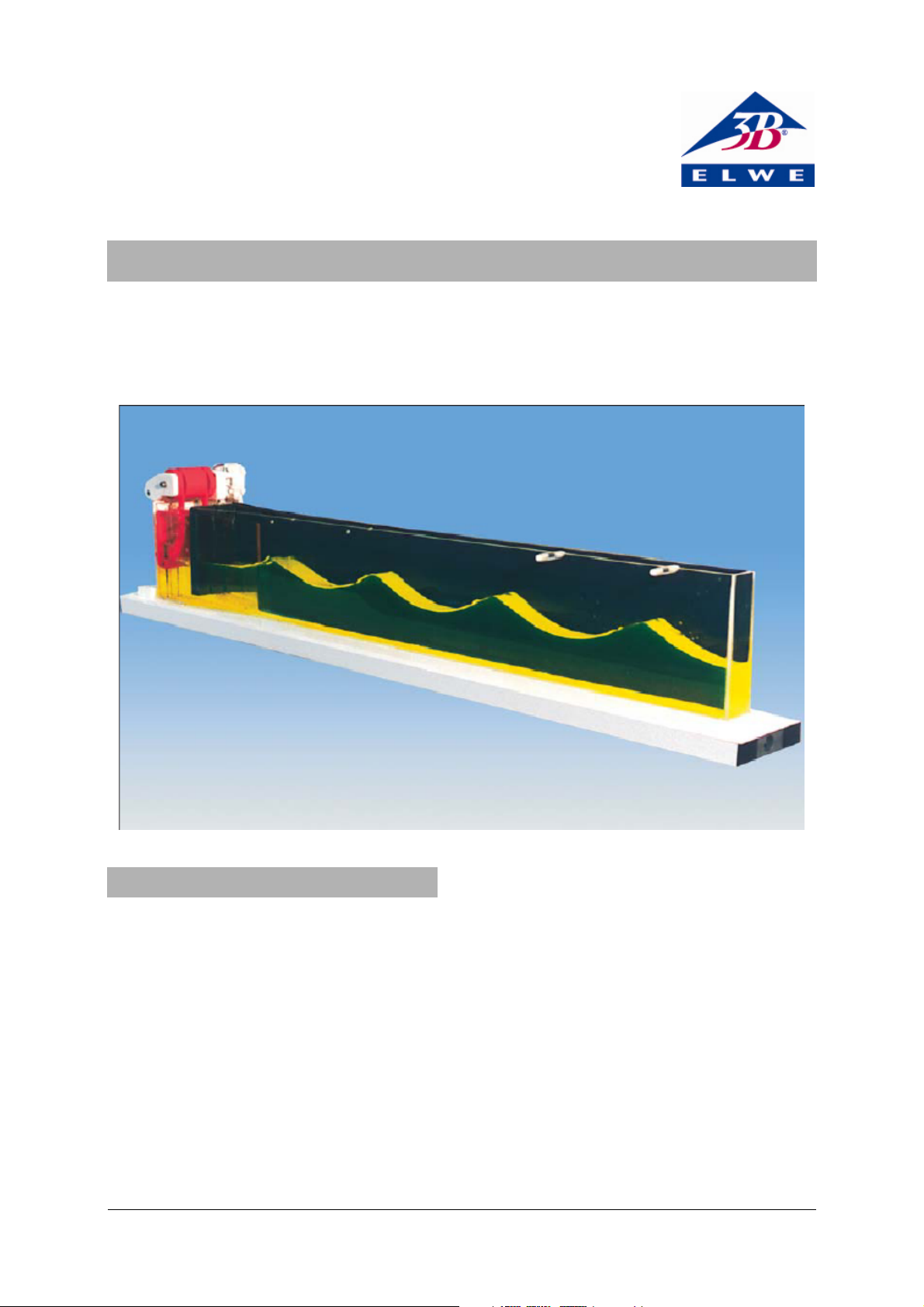
Water Wave Channel 1000807
Instruction sheet
05/12 ELWE/ALF
®
PHYSICS
1. Description
The water wave channel serves for the demonstration and investigation of surface waves in water.
It consists of a large transparent oblong trough,
which is two-thirds filled with water.
The waves are produced in the short V-shaped
section and studied in the I-shaped section. For the
generation of the waves a motor with transmission
is attached at the end of the V-shaped channel. It
propels two wave exciters, which move up and
down in the water. Each exciter produces a wave in
a section of the V-shaped channel. Depending
upon the setting, the two exciters can move in the
same direction or in contra motion. The frequency
of these waves can be varied by changing the operating voltage of the motor.
In both partial channels there is a frame with a
fleece directly in front of the wave exciters which
the waves must pass through. Thus to a large extent a sinusoidal process is achieved. Then the
waves enter the I-shaped part of the channel and
move along to its end. If the absorbing frame with
fleece is introduced at the end of this channel,
then they are dissipated as far as possible. Thus a
continuous wave pattern develops in the channel.
If the absorber is not inserted, the waves travel to
the end of the I-shaped channel and are reflected.
With a short switch-on time of the motor, a wave
train develops which travels through the channel
and is reflected and travels back towards the exciter. With continuous operation of the motor the
arriving and the reflected waves overlap, producing
an image of a motionless standing wave.
4
Page 2

If the wave absorbed at the end of the I-channel is
produced by only one wave exciter (by blocking the
second partial channel), then its amplitude is
small. If both partial waves arrive into the I-shaped
part of the channel, then the amplitude increases.
By inserting the separator into the transient area
between the V-shaped channel and the I-shaped
channel, the two partial waves run separately in
the I-shaped channel and their motions can be
compared with one another. If the two wave exciters are operated in contra motion then the phase
shift from λ/2 can be clearly observed in the area
of the inserted glass plate. The overlap of these two
partial waves leads to the fact that after they enter
the rear part of the I-channel they cancel each
other out to the greatest extent possible.
The following experiments can be carried out with
the water wave channel:
Production of a non-periodic wave
Production of a periodic wave
Proof that waves transport energy, but not material
Phase and group velocity of a wave
Determination of the phase velocity
Demonstration of the relationship between frequency and wavelength
Reflection of a wave
Standing waves
Same-phase overlapping of waves
Overlapping of waves with a phase shift of λ/2
1.1 Accessories
2 Frames with fleece for the homogenisation of
the waves (primary absorber)
1 Frame with fleece for the supression of the
wave reflection at the end of the channel (secondary absorber)
1 Tube for the temporary blocking of a partial
channel
1 Transparent separator 40x170x6 mm
3
with
spacer pieces for inserting into the I-shaped
channel
2 Plastic balls with thread for the proving the up
and down movement
1.2 Additionally required apparatus
1 Power supply unit for DC voltage, 0 ... 20 V,
continuously variable
1 Reflector lamp
Fluoreszein for colouring the water
2. Technical data
Operating voltage of motor: 12 V DC
Dimensiones: 1500 mm x 150 mm x 290 mm
Mass: approx. 12.6 kg
3. Operation
• Fill up the water wave channel to the marked
height with water, to which some fluoreszein
has been added (fig. 1).
• The lighting with the reflector lamp takes place
diagonally from above, so that a fluorescent
layer appears on the water surface.
• Connect the motor to the power supply unit.
• Into the two partial channels of the V-shaped
part, a conical frame with fleece is introduced.
• At the end of the I-shaped part, the absorber
frame with fleece is introduced at such an angle that the waves at the surface travel very
flatly over it.
• Switch on the motor.
The image of a spreading wave develops.
In order to change the phase position of the two
partial waves, one of the rollers on the wave exciter
is rotated through 180° until it engages.
The voltage for the motor can be increased briefly
to approximately 13 V. The amperage is smaller
than 0.5 A. The switch for the motor has three
positions. In the middle position the motor is
switched off. When pressed to one side, the motor
is switched on and remains on until the switch is
returned to the off position (continuous mode).
When pressed in the other direction, the motor is
switched on and remains on only whilst pressure is
maintained (pulse mode). In this mode short wavelengths can be produced.
• When the experiments are completed put a
water bucket under the end of the I-shaped
channel.
To empty the channel a fatigue proof plastic tube
connected to the channel inside is stored in the
grey box at the end of the channel.
• To drain the water, carefully take the tube out
of the box (one end is fixed to the drain noz-
zle).
• Slightly strech the tube and place the free end
into the bucket.
The water will be drained automatically.
• After draining the channel fold the tube in its
original zigzag configuration and push it back
into the box.
2
Page 3

4. Sample experiments
4.1 Generation of a non-periodic wave
Firstly, adjust both exciters so as to produce the
same phase movement.
• Introduce the absorber frame at the end of the
I-shaped part of the wave channel.
• Switch on the motor for approx. 1 s.
A short wave train develops which moves through
the wave channel (fig. 2).
4.2 Generation of a periodic wave
• Switch on the motor for a longer time.
A progressive periodic wave develops at the exciter
and travels to the end of the I-channel.
4.3 Proving that waves transport energy, but
not material
• Attach the two plastic balls in the middle part
of the I-shaped channel by their threads to different places on the channel wall.
• Switch on the motor briefly
When the balls are met by the wave train, they
move rhythmically over and back like the water
particles. After the wave train moves through, the
balls are still in the same position.
4.4 Determining the phase velocity of a wave
• Measure the time which a wave peak needs to
travel from the entrance of the I-shaped channel to the absorber with motor running.
The speed is calculated as a quotient of distance
and time.
4.5 Relationship between frequency and wavelength
• First operate the motor with a low voltage.
• Measure the wavelength.
• Then increase the frequency of the motor and
again determine the wavelength.
• Repeat the experiment with a still greater
number of revolutions of the motor.
The greater the frequency of the wave, the smaller
is the wavelength.
4.6 Reflection of the water wave
• Remove the absorber frame from the end of
the I-channel.
• Switch on the motor for approx. 1 s.
A short wave train develops, which moves up to the
end of the I-channel. There it is reflected and travels back towards the wave exciter.
4.7 Phase velocity and group velocity
• Switch on the motor for approx. 2 s.
It is clearly visible that the wave peaks move with
greater speed to end of the I-channel and after the
reflection, from there towards the wave exciter
than the entire group of waves.
4.8 Standing waves
• Switch on the motor.
The wave is reflected at the end of the I-channel.
The reflected wave overlaps with the arriving wave.
A standing wave develops. A convincing image of a
standing wave can be achieved with a slight adjustment of motor speed.
4.9 Same-phase overlapping of waves
• Introduce the wave absorber again at the end
of the I-channel.
• Switch on the motor.
• First block the exit of the partial channels with
the cylindrical body.
• Determine the amplitude of the wave after it
enters the I-channel (fig. 3).
• Open the second partial channel again and
determine the amplitude again at the same location.
It is now greater than in the first instance by a
factor of √2. (fig. 4).
4.10 Overlap of waves with a phase-shift of 1/2
• Rotate the sleeve on the exciter paddle in such
a way that the exciters move in contra-motion.
• Introduce the separator plate into the area
between the V-shaped section and the I-shaped
section.
• Switch on the motor.
Where the separator is situated, the out of phase
situation of the two partial waves is clearly visible.
In the I-shaped part of the channel which is not
separated by the plate, the two partial waves meet
and cancel each other out (fig. 1).
The fact that standing waves are formed in the area
of the channel with the separator
plate is to be due to the reflection of the partial
waves behind the separating plate. If the exciter is
only switched on briefly, then it is noticed that the
two partial waves move up to the overlapping position. There they are then reflected back into both
channels.
3
Page 4

Fig. 1 Experimental set-up of the wave channel
Fig. 2 Generation of a non-periodic wave
Fig. 3 Same-phase overlapping of waves
4
Page 5

Fig. 4 Same-phase overlapping of waves
Elwe Didactic GmbH • Steinfelsstr. 6 • 08248 Klingenthal • Germany • www.elwedidactic.com
3B Scientific GmbH • Rudorffweg 8 • 21031 Hamburg • Germany • www.3bscientific.com
Subject to technical modifications
© Copyright 2012 3B Scientific GmbH
Page 6

 Loading...