

Page 1
3B SCIENTIFIC® PHYSICS
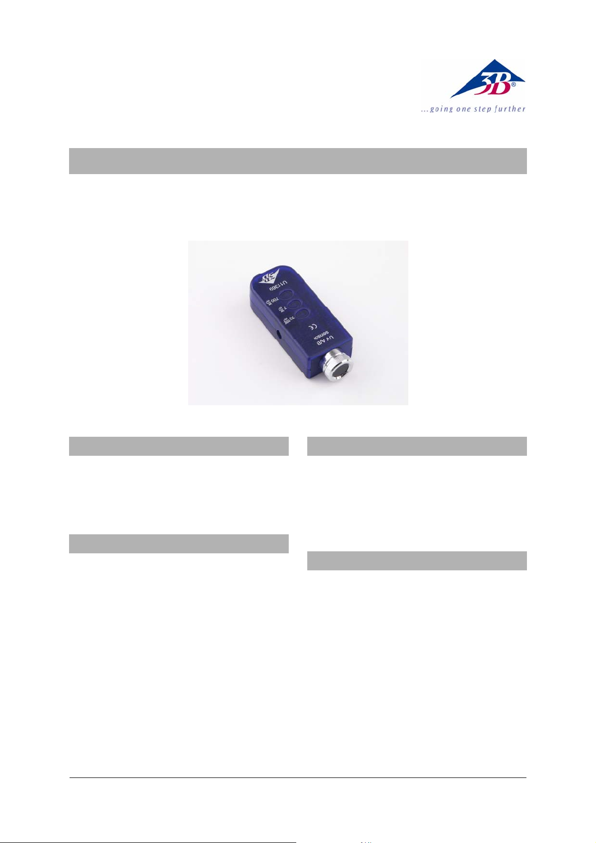
UV A/B sensor U11369
Instruction sheet
06/09 Hh
1. Safety instructions
The UV A/B sensor is not suitable for safety-related
applications.
• The UV A/B sensor may only be used for
educational purposes.
2. Description
Sensor box containing photodiode with built-in
optical filter to cut out visible light for
measurements in the UVA/UVB spectral regions.
Push-button selection of measurement ranges
70 mW/m², 7 W/m² or 700 W/m², with visible range
indicator.
Screw-on aperture cover to accommodate the
supplied UG-1 coloured glass insert to be used as a
UVA filter.
The sensor box and the selected measurement range
are detected automatically by the 3B NETlog
TM
unit.
3. Equipment supplied
1 UV A/B sensor with removable aperture cover and
UVA filter (SCHOTT UG-1)
1 Stand rod with screw-thread, 120 mm
1 8-pin miniDIN connecting lead, length 600 mm
1 Instruction sheet for U11369
4. Technical data
Measurement ranges: 0 to 70 mW/m²
0 to 7 W/m²
0 to 700 W/m²
Sensor type: Titanium dioxide
Schottky diode with
built-in filter to cut
out visible light
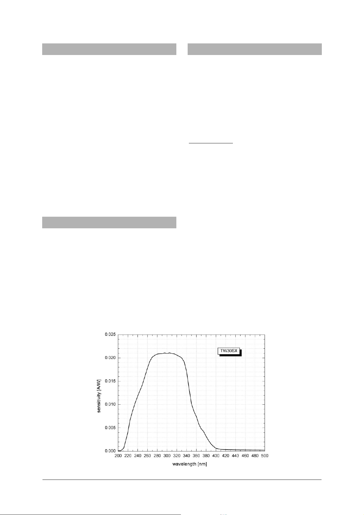
Max. spectral sensitivity: Typically 21 mA/W
Wavelength for max.
spectral sensitivity: 300 nm
Visible light blocking factor: 50
Spectral sensitivity
characteristic of UV diode: See fig. 1
Transmittance characteristic
of UVA filter: See fig. 2
1
Page 2
5. Operation
7. Sample experiment
• Place the sensor box close to the experiment.
• Switch on the 3B NETlog
TM
unit and connect the
UV A/B sensor via the miniDIN cable to one of its
two analogue inputs (A or B).
• Wait for the sensor box to be detected
automatically.
• Select the appropriate measurement range for
the expected UV intensity depending on the light
source [e.g., sunlight, UV light for tanning (sunbeds, solaria) or UV disco lights].
• Read the value of the light intensity from the
display of the 3B NETlog
• If the measurement range is exceeded, change
TM
unit.
to the next higher range.
• For transmission measurements, hold the
absorber specimen between the light source and
the sensor and calculate the ratio of the
radiation intensity readings with and without
the absorber (the transmission coefficient).
6. Applications
Measuring the UV intensity during the course of a
whole day and investigating its dependence on the
time of year.
Measuring the UV transmittance (transmission
coefficient) of different glass and plastic lenses in
sunglasses and normal spectacles.
Comparing the UV transmittance of the windscreen
and side windows of a car with regard to possible
tanning or sunburn of occupants.
Does wet clothing give better protection from UV
radiation than dry clothing?
Quantitative comparison of the radiation protection
factors of sun-creams.
Measurements of the UV transmittance
(transmission coefficient) of different glass and
plastic materials in sunglasses and normal
spectacles
Equipment required:
1 3B NETlog
1 3B NETlab
TM
U11300
TM
U11310
1 UV A/B sensor U11369
Several different pairs of sunglasses and normal
spectacles
Recommendation
: Perform the experiment outdoors
on a sunny day.
• Switch on the 3B NETlog
TM
unit and wait for the
sensor box to be detected automatically.
• Select the 700 W/m
2
measurement range on the
sensor box.
• Select the program (template) “Ultraviolet
radiation” on the 3B NETlog
• Hold the UV A/B sensor in sunlight, without the
TM
unit.
aperture cover and without the UVA filter, and
start the program.
• Choose the “Manual input” mode and record the
first of two intensity measurements.
• Hold one lens of the sunglasses in front of the
UV A/B sensor at a distance of about 10 cm.
• Now make the second intensity measurement.
• Make a graph of the two measurements to show
the effect of the lens (Fig. 3).
• If possible, repeat the experiment with another
pair of sunglasses.
Fig. 1 Spectral sensitivity characteristic of UV diode
2
Page 3

Fig. 2 Transmittance characteristic of UG-1 filter
Fig. 3 Measurements as displayed on screen in 3B NETlabTM (U11310) from above experiment
3B Scientific GmbH • Rudorffweg 8 • 21031 Hamburg • Germany • www.3bscientific.com
Subject to technical amendments
© Copyright 2009 3B Scientific GmbH
Page 4

 Loading...