

Page 1
3B SCIENTIFIC® PHYSICS
40 kHz Ultrasonic Transducer Equipment Set 1009888
Instruction manual
06/12 ALF
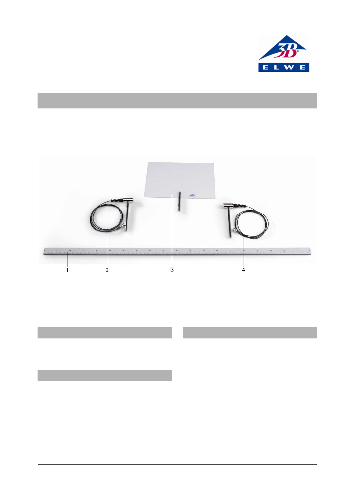
1 Ruler
2 Ultrasonic transmitter (S)
3 Ultrasonic receiver (R)
4 Projection screen
1. Note
• Do not use the ultrasonic transducer in
liquids.
2. Description
The 40 kHz ultrasonic transducer equipment set
is designed for experiments on geometric
acoustics and wave mechanics.
The equipment set consists of an ultrasonic
transmitter (S) and an ultrasonic receiver
both mounted on stems, a projection screen, also
on a stem, and a ruler.
(R),
3. Technical data
Input voltage: 10 V AC max.
Resonant frequency: 40 kHz approx.
Band width: 6 kHz approx.
Angle of aperture: 72°
Capacitance: 1900 pF
Connector: Co-axial cable with
BNC plug
Stand rod: 150 mm x 10 mm diam.
Dimensions: 40 mm x 20 mm diam.
1
Page 2
4. Additionally required equipment
1 Function generator FG 100 (230 V, 50/60 Hz)
1009957
or
1 Function generator FG 100 (115 V, 50/60 Hz)
1009956
1 Analogue oscilloscope 2x30 MHz 1002727
3 Stand bases, 0.5 kg 1001046
1 HF cable 1002746
1 T-Piece, BNC 1002752
1 Adapter, BNC Jack/4-mm-Plugs 1002751
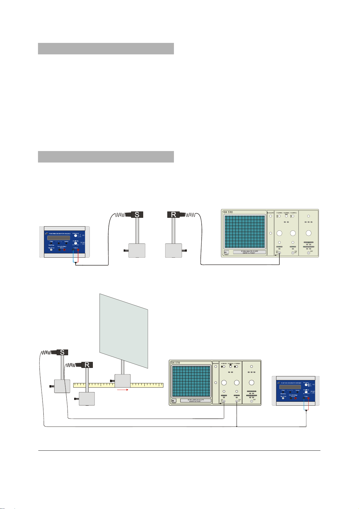
5. Operation
5.1 Calibration of resonant frequency
• Set up the ultrasonic transmitter and receiver
close together and facing one another.
• Connect the transmitter to the output of the
function generator and set the frequency to
40 kHz.
• Connect the receiver to an oscilloscope.
• Observe the received signal and make fine
adjustments to the frequency to maximise the
signal amplitude.
5.2 Sample experiment
• Set up the ultrasonic transmitter and receiver
alongside one another in front of the
projection screen.
• Connect the transmitter to the output of the
function generator and set the frequency to
the resonant frequency (see 5.1).
• Connect the receiver to the oscilloscope.
• Move the projection screen and observe the
phase differences between the signals.
Fig. 1 Experiment set-up for calibrating resonant frequency
Fig. 2 Experiment set-up for the reflection of ultrasonic waves by a projection screen
Elwe Didactic GmbH ▪ Steinfelsstr. 5 ▪ 08248 Klingenthal ▪ Germany ▪ www.elwedidactic.com
3B Scientific GmbH ▪ Rudorffweg 8 ▪ 21031 Hamburg ▪ Germany ▪ www.3bscientific.com
Subject to technical amendments
© Copyright 2012 3B Scientific GmbH
 Loading...