

Page 1
3B SCIENTIFIC® PHYSICS
... going one step further
Sample experiments for Optics on magnetic boards, basic kit
U14600 with Multiple-ray projector U40110
08/03 ALF
Exp.1: Reflection on a plane mirror
Demonstration of the law of reflection. An
incident ray is projected to the mirror
surface under the angle α and reflected
under the same angle α’.
Exp.2: Virtual image in a plane mirror
Two rays of light are projected through
point O to a plane mirror. The extensions
of the reflected rays intersect in the image
point O’.
Exp.3: Focal length of a concave
mirror
The centre of curvature C of the concave
mirror is located by means of a ray which
reflects on itself. Rays parallel to the
principal axis intersect in the focal point F.
The distance of the centre of curvature C
is twice as long as the distance of the
focus F.
f = r/2
In case the rays are non-parallel to the
optical axis, the reflected rays intersect in
a point on an axis which is referred to as
the focal plane. The focal plane passes
through the focal point and is
perpendicular to the optical axis.
Page 2
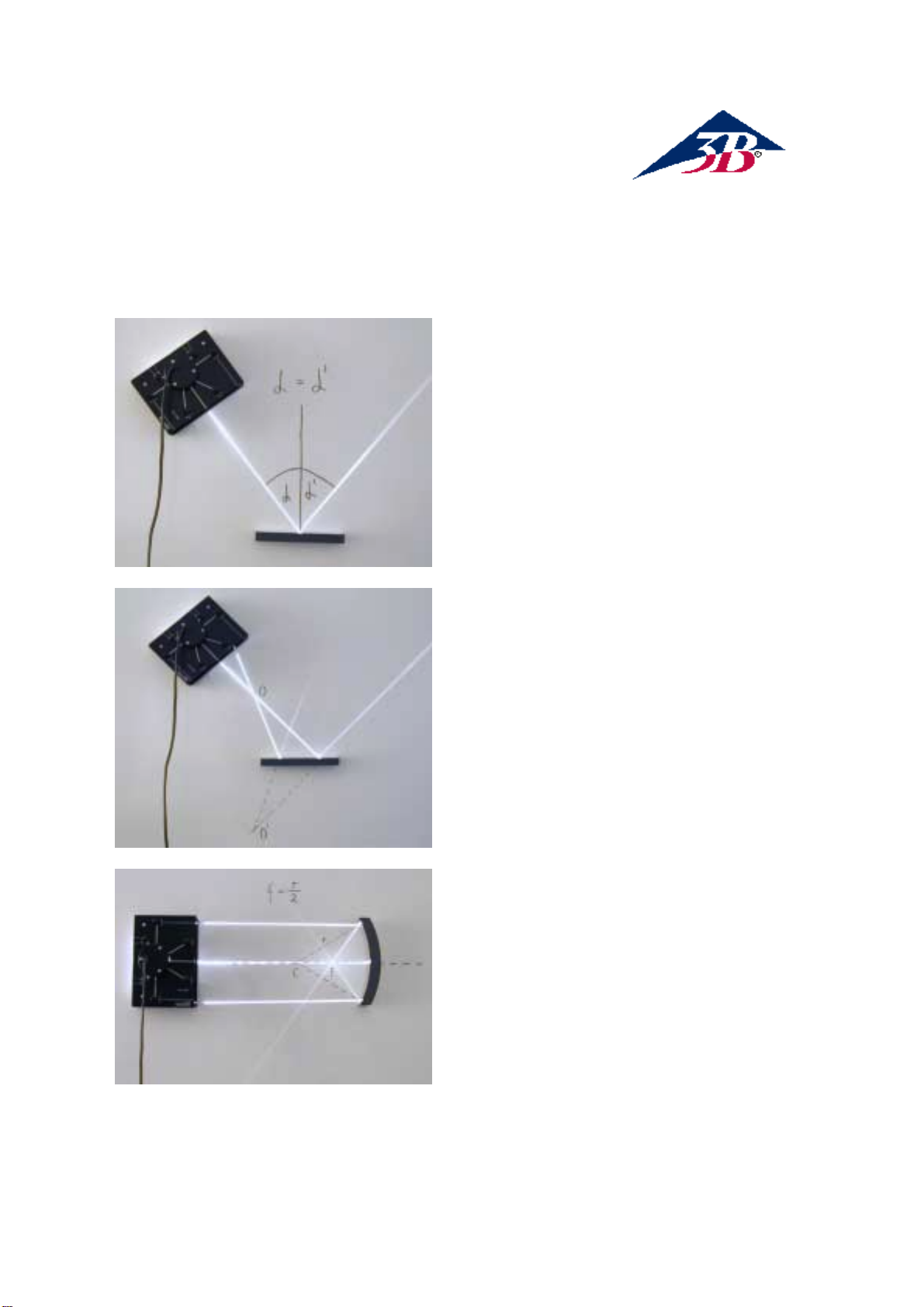
Exp.4: Real image formed by a
concave mirror
The optical axis is located by means of a
ray which reflects on itself. Two rays of
light, one parallel to the optical axis and
the other through the focal point F, are
made to intersect at the object point
(upright arrow). The reflected rays
intersect at the image point (inverted
arrow).
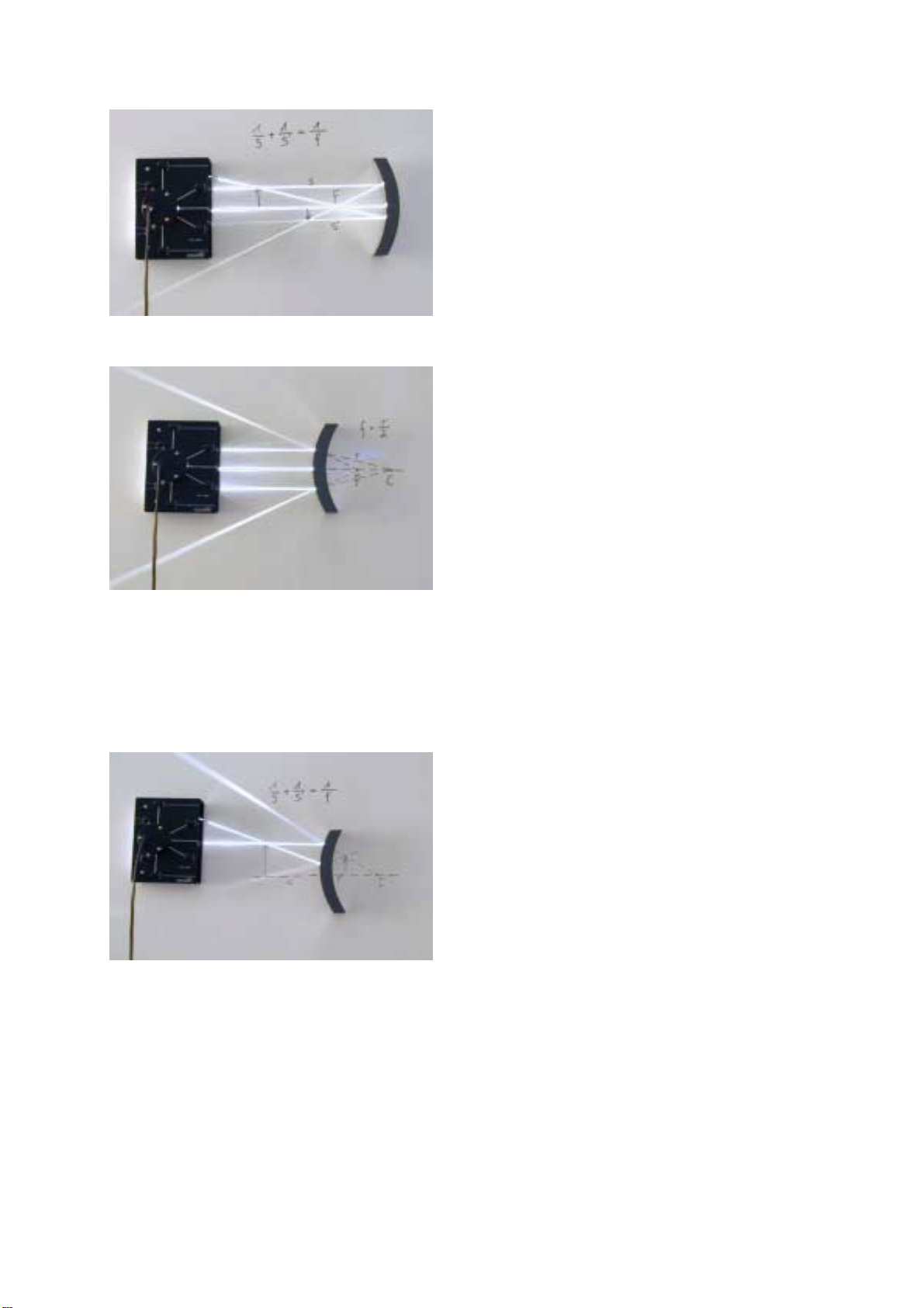
Exp.5: Focal length of a convex mirror
The centre of curvature C of the concave
mirror is located by means of a ray which
reflects on itself and is extended behind
the mirror. The reflections of two parallel
rays are also extended in the same
manner until they intersect in the focal
point. The distance of the center of
curvature C is twice as long as the
distance of the focus F. f = r/2
In case the rays are non-parallel to the
optical axis, the reflected rays intersect in
a point on an axis which is referred to as
the focal plane. The focal plane passes
through the focal point and is
perpendicular to the optical axis.
Exp.6: Virtual image formed by a
convex mirror
Two rays, one of them parallel to the
optical axis; are made to intersect at the
object point (upright arrow). The
extensions of the reflected rays are drawn
behind the mirror. The virtual image
(inverted arrow) is erect and smaller than
the object.
Page 3

Exp.7: Refraction from a less dense to
a more dense medium
A pencil of light is projected at the upper
surface of the plane-parallel plate. The
normal and the extension of the refracted
ray are drawn on the white board. The
phenomenon of refraction is clearly
visible. If light passes from a less dense
to a more dense medium the refraction
angle β is smaller than the incidence
angle α.
Exp.8: Refraction from a more dense
to a less dense medium
The plane mirror is set behind the planeparallel plate. It produces a return pencil
of light which demonstrates the deviation
away from the normal when the ray
passes from the more dense to the less
dense medium. Incident angle α and
emergent angle β are equal.
Exp.9: Parallel displacement by a
plane-parallel plate
If a light ray passes through a planeparallel plate its direction is not changed.
The shift v of the outgoing ray can be
determined by using the formula:
v = d*sin(α-β)/cosβ
Exp.10: Semi-circular body
_
Light
incident at the center
If a light ray passes through the centre of
curvature of a semi-circular body it will
emerge perpendicular to the tangent at
the point of emergence and will undergo
no second deviation.
Page 4

Exp.11: Semi-circular body _ Light
incident at right angle to tangent
If a light ray perpendicular to the tangent
passes through a semi-circular body it will
not be deviated. The ray is refracted at
the point of emergence with the refraction
angle β, which is larger than α. It is bent
away from the normal. Partial internal
reflections occur at incident angles
smaller than the critical angle in the
dense medium.
Exp.12: Semi-circular body _ Critical
angle
A pencil of light is projected along the
extension of a radius of the disc. The
semi-circular body is rotated until total
internal reflection occurs. The critical
angle α can easily be measured.
Exp.13: Triangular Prism- Total
internal reflection, 90° deviation
When the ray impinges the edge of the
triangular prism, it is totally reflected. If
the prism is slightly adjusted reflection
and refraction can be observed. The 90°
deviation is used in the design of some
modern periscopes.
Exp.14: Triangular Prism- Total
internal reflection, 180° deviation
The conditions for total reflections are
fulfilled on both edges of the prism. The
basic principle of prism binoculars is
demonstrated.
Page 5

Exp.15: Reversing prism
In this experimental setup total internal
reflection and refraction cooperate to
reverse the positions of the two parallel
rays.
Exp.16: Angle of minimum deviation
The deviation of a pencil of light through
the prism is most easily observed when
the light passes through the prism just
below one of the 45° angles. The angle of
minimum deviation is quickly found
experimentally.
Exp.17: Focal Length of a planoconvex lens
The focal length of a plano-convex lens is
determined by two rays parallel to the
optical axis. They intersect in the focal
point F.
Exp.18: Focal Length of a planoconcave lens
Two rays parallel to the optical axis are
refracted by the plano-concave lens.
Extensions of the refracted rays are
drawn on the board until they intersect in
the focal point F.
Page 6

Exp.19: Virtual image formed by a
concave lens
Two pencils of light, one parallel to the
optical axis and the other through the
optical centre, intersect in the object
point. The refracted ray due to the parallel
ray is extended until it intersects the ray
passing through the centre. The virtual
image is smaller than the object
Exp.20: Cancelling out of the
refraction
When light rays pass through an object
made up of a concave and a convex lens
with the same curvature the refraction is
cancelled out.
Exp.20: Shadow casting
Light rays from the reverse side of the
multiple-ray projector are used for
experiments on shadow-casting.
Exp.21: Eclipse of the sun
The two round shadow-casting bodies are
placed on the board to represent the
moon and the earth. When the moon’s
shadow strikes the earth a solar eclipse
can be observed, partial in the penumbral
and total in the umbral shadow..
3Bscientific GmbH ● 21031 Hamburg ● Germany ● www.3bscientific.com ● Technical amendments
are possible
 Loading...