

Page 1
3B SCIENTIFIC
Stirling Engine, Transparent 1003000
Instruction sheet
04/12 JS
®
PHYSICS
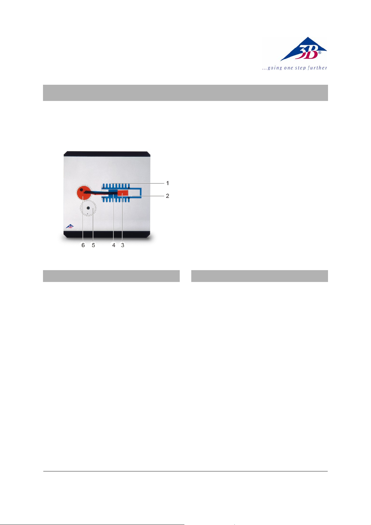
1 Cold side
2 Hot side
3 Working piston
4 Displacement piston
5 Flywheel
6 Crank shaft
1. Description
The way a Stirling engine works can be divided
into four sections, or piston strokes.
1) Heat is fed to the system when the displacement piston pushes the air to the heated side of
the displacement cylinder. At this time the piston
is in a position known as top dead centre, here
at its rightmost extreme.
2) Expansion of heated air drives the working
piston towards the left. This causes mechanical
work to be transferred via the crankshaft to the
flywheel.
3) Heat is dissipated when the displacement
piston causes the air to move to the cooler side
of the displacement cylinder.
4) The cooled air is compressed as the working
piston moves to the left, the mechanical energy
(work) for this being provided by the flywheel.
2. Operation
Additionally recommended:
Overhead Projector (230 V, 50/60 Hz) 1003264
or
Overhead Projector (115 V, 50/60 Hz) 1003263
• Lay the transparency on the daylight projec-
tor.
• Move the components by hand to the places
which correspond to the various strokes.
3B Scientific GmbH ▪ Rudorffweg 8 ▪ 21031 Hamburg ▪ Germany ▪ www.3bscientific.com
Subject to technical amendments
© Copyright 2012 3B Scientific GmbH
Page 2

 Loading...