

Page 1
3B SCIENTIFIC® PHYSICS
Demonstration oscilloscope U8481350
Instruction sheet
01/08 CW/ALF
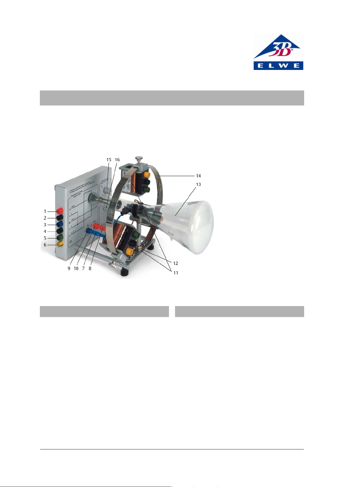
Inputs:
1 Anode voltage
2 Cathode voltage
3 Wehnelt (focussing) voltage
4 Heater voltage (0)
5 Heater voltage (+)
6 Chassis ground
7 Deflecting plate (left)
8 Deflecting plate (right)
Outputs:
9 Saw-tooth generator (-)
10 Saw-tooth generator (+)
11 Deflecting coils
12 Circular magnet (obscured by
deflection coil)
13 Cathode ray tube
14 Metal ring
15 Coarse adjustment for saw-
1. Safety instructions
tooth frequency
16 Fine adjustment saw-tooth
frequency
2. Description
The demonstration oscilloscope is operated with voltages, some of which are above 60 V.
• Always turn off power supply before making con-
nections.
• Use safety leads.
Since the glass tube is evacuated, there is an implosion hazard.
• Do not subject the tube to sharp blows or me-
chanical stress.
In schools and training institutions, operation of the
device is to be responsibly supervised by trained personnel.
The demonstration oscilloscope can be used to show
the deflection of an electron beam by electric and
magnetic fields, just as employed in TVs or conventional oscilloscopes. Essentially, it consists of a cathode ray tube that is supplied with voltage via 4-mm
plugs and is surrounded by a ring, to which deflecting
coils can be attached.
A cathode ray tube is an evacuated glass tube, the
neck of which contains a heated cathode and an anode in the shape of a disc with a hole in the middle,
separated by a distance of approximately half a centimetre. Electrons emitted from the heated cathode
are accelerated towards the anode. Some of them
pass through the hole to form a beam that strikes the
fluorescent screen (with zinc silicate coating) and thus
becomes visible as a green fluorescent dot. The beam
is focussed partly by a Wehnelt cylinder surrounding
the cathode, the potential of which is negative with
1
Page 2
respect to the cathode potential, and partly by gas
constriction as a result of the tube being filled with
neon at a pressure of 0.01 mm Hg that also renders
the beam visible inside the tube.
There are also two opposing deflection plates in the
tube, oriented parallel to the beam, which can be
connected to the integrated saw-tooth generator, or
to an external voltage supply. The generator supplies
saw-tooth voltage waveforms with a frequency range
of 3.5 to 650 Hz and an amplitude of 100 V relative to
the anode potential.
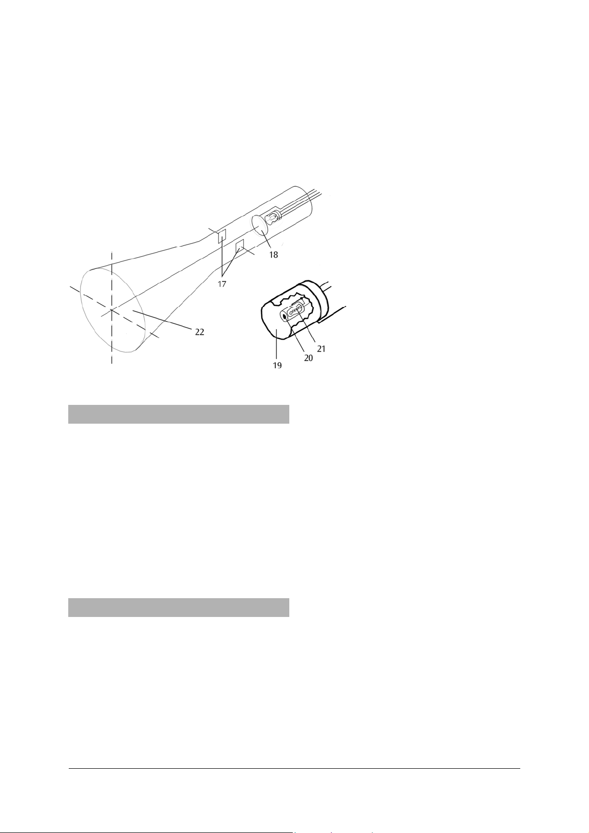
Tube:
17 Deflection plates
18 Anode
19 Wehnelt cylinder
20 Cathode
21 Heater
22 Fluorescent screen
Fig. 1: Cathode ray tube
3. Technical data
Anode voltage: 250 V DC
Anode current: 1 mA max.
Heater voltage: 6...8 V AC/DC
Wehnelt voltage: -50...0 V DC
Size of deflection plates: 12 x 20 mm²
Distance of deflection plates: 14 mm
Deflecting coils: 300 + 300 turns
R
= 4.2 Ω
i
L = 6 mH
Saw-tooth voltages: V
= 100 V
pp
f = 3.5..650 Hz
4. Operation
4.1 To start operation
In order to supply current to the demonstration oscilloscope, power supplies are required that can output
the following voltages:
+250 V DC,
0-50 V DC, regulated,
6-8 V DC, regulated.
Power supplies U8521371 and U33000, which can
supply all of these voltages, are particularly well
suited to this end.
• Turn off the power supply.
• Connect the inputs of the demonstration oscillo-
scope to the outputs of the power supply, that
supply the specified voltages.
• Adjust the voltage so as to not to exceed the lim-
its.
• Turn on the power supply.
After 10-30 sec, a green spot appears on the fluorescent screen, which denotes where the electron beam
is hitting the screen. In order to keep the tube as
simple and clear as possible for educational purposes,
it was decided to do without additional apparatus for
secondary acceleration and focusing of the beam. For
this reason, it is not usually possible to focus the
beam to the sharpness seen in conventional oscilloscopes.
• Vary the Wehnelt voltage until the spot reaches its
minimum dimensions.
The electron beam is visible as a reddish thread inside
the tube, but only in a darkened room because of its
low intensity.
4.2 Deflecting apparatus
4.2.1 Electrical deflection
Using the deflecting plates located inside the tube,
the electron beam can be deflected horizontally by
applying a voltage of up to 100 V. For most applica-
2
Page 3

tions, a saw-tooth generator is used to supply this
voltage. In this case, the beam goes from left to right
and then quickly flicks back again. This is repeated at
a fixed frequency that can be adjusted. By this means
it is possible to display vertical deflections that are
also periodic, such as an alternating magnetic field.
4.2.2 Magnetic deflection
Attach the coils to the magnetic ring surrounding the
neck of the tube. Between each neighbouring socket,
there are 300 turns so that if a connection is made to
the two outer sockets, the current flows through all
600 turns. The electron beam is deflected to the right,
perpendicular to the magnetic field and the direction
of the beam. If the coils are mounted facing inward,
even small currents of a few milliamps will be noticeable.
4.2.3 Beam adjustment
A magnet is attached to the tube support in the mid-
dle that can be adjusted by a screw so that the beam
can be aligned to strike a specific point on the screen
when the deflecting apparatus is turned off.
4.3 Saw-tooth generator
The outputs of the saw-tooth generator are located
below the mounts at the rear of the tube and are
labelled -U
and +Ux, respectively.
x
A saw-tooth voltage (also frequently called a ramp) is
a voltage that changes periodically over time, increasing or decreasing linearly from an initial value then
returning instantaneously to the start.
Caution: the saw-tooth voltage is relative to the anode
potential of +250 V.
The upper knob is used to turn on the generator and
make a coarse adjustment of the frequency. Fine
adjustment is completed with the lower knob.
5. Sample experiments
5.1 Electrical deflection of the electron beam
• Set up the experiment as in fig. 2.
• Turn off the voltage supply to the demonstration
oscilloscope
• Connect deflecting plates to the output of the
saw-tooth generator.
• Adjust the electron beam so that it strikes the
fluorescent screen on the left-hand side (about 1
cm from the edge).
• Set the coarse adjustment of the saw-tooth fre-
quency to its minimum level (second position
from the left).
• Turn on the voltage supply.
After 10-30 sec, the fluorescent dot appears on the
screen. It should migrate periodically from left to
right.
• If necessary, decrease the frequency using the
fine adjustment knob so that the migration of the
point can be clearly tracked.
5.2 Magnetic deflection of the electron beam
• Set up the experiment as in fig. 3.
• Attach a coil to the metal ring.
• Connect the inputs of the coil to the DC power
supply.
• Adjust the electron beam so that it strikes the
centre of the fluorescent screen.
• Turn on the DC power supply and vary the current
to the coil.
The beam is deflected perpendicularly to the direction of both the beam and the magnetic field.
• Change the polarity and alignment of the coil and
the number of turns the current flows through
and observe the effects.
5.3 Trace of an AC voltage over time
Additional equipment required:
1 Function generator (50 Ω, with amplifier if possible)
or AC power supply.
Optional: 1 Multimeter with frequency counter
(maximum voltage, at least 150 V).
• Set up the experiment as in fig. 4.
• Follow the instructions for experiment 5.1, but do
not decrease the frequency, and set the coarse
adjustment to the medium level. If a multimeter
with frequency counter is available, connect it to
the outputs of the saw-tooth generator in parallel
with the deflection plates before turning on the
voltage supply. (Caution: it is dangerous to touch
the saw-tooth voltage outputs)
• Attach a coil to the metal ring.
• Connect the inputs of the coil to the function
generator (amplified if available).
• Select a frequency between 30 and 100 Hz on the
function generator.
During movement from the left to the right side, the
beam is vertically deflected.
• If necessary, increase output voltage to obtain a
bigger deflection.
Due to the rapid repetition, it is hard to see a waveform for the AC voltage, since recording usually does
not start the same point during the period (the same
phase) so that multiple phase-shifted images are
therefore superimposed. This problem does not occur
if the saw-tooth frequency is identical to the input
signal frequency of the function generator.
3
Page 4

• With the fine adjustment, search for a frequency
at which a standing image appears, which shows
a clear period of oscillation.
At which other saw-tooth frequencies does a standing
image also appear?
5.4 Lissajous figures
Additional equipment required:
1 Function generator (50 Ω, with amplifier if possible), and 1 AC power supply or 2 function generators.
• Set up the experiment as in fig. 5.
• Attach a coil to the metal ring pointing inward,
with the axis aligned horizontally.
• Connect the inputs (green, yellow) to the AC
power supply or to the second function generator
(set to a 50 Hz sinusoidal voltage). Select the amplitude so that the line appearing on the screen is
approximately half the length of the screen diameter.
• With the circular magnet, adjust the line horizon-
tally to centre it.
• Mount another coil to the metal ring pointing
inward, with the axis aligned vertically.
• Connect the inputs (green, yellow) to the first
function generator (set to a 50 Hz sinusoidal voltage).
An ellipse appears that changes shape at faster or
slower speed, depending on how well the frequencies
of the input signals match. This takes the shape of a
sloped straight line twice per cycle.
• Adjust the amplitude of the first function genera-
tor so that the slope of the straight line is 45° and
that a circle emerges during transition.
The simplest Lissajous figures can be observed already. The shapes depend on the frequency ratios and
on the phase shift. Due to a small deviation from the
exact target frequency on either of the two function
generators (usually, the inaccuracy of the devices is
already sufficient), the phase shift cycles automatically, and all figures for a specific frequency ratio can
be observed in succession.
• Set the frequency of the first function generator
to a multiple of the horizontal frequency (50 Hz).
Observe Lissajous figures for the frequency ratios 2:1,
3:1 and 4:1.
• Further Lissajous figures are created by fractional
multiples of the horizontal frequency (e.g., 3:2 (75
Hz), 4:3 (66.7 Hz).
Fig.2 Electrical deflection of the electron beam (left: with power supply U8521371, right: with power supply U33000)
4
Page 5

Fig.3 Magnetic deflection of the electron beam (left: with power supply U8521371 and power supply U33020, right: with
power supply U33000)
Fig.4 Trace of an AC voltage over time (left: with power supply U8521371 and function generator U21015, right: with power
supply U33000 and function generator U21015)
5
Page 6

Fig.5 Generating Lissajous figures (left: with power supply U8521371 and 2x function generator U21015, right: with power
supply U33000 and 2x function generator U21015)
Elwe Didactic GmbH • Steinfelsstr. 6 • 08248 Klingenthal • Germany • www.elwedidactic.com
3B Scientific GmbH • Rudorffweg 8 • 21031 Hamburg • Germany • www.3bscientific.com
Subject to technical amendments
© Copyright 2008 3B Scientific GmbH
 Loading...