

Page 1
3B SCIENTIFIC
Instruction sheet
03/11 Alf
®
PHYSICS
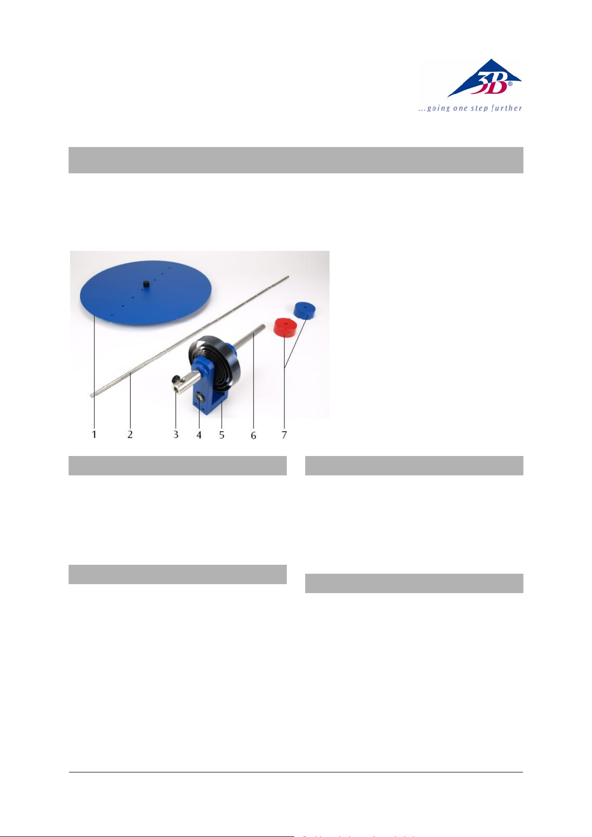
Torsion Axle U20050
1 Circular disc
2 Cross bar
3 Mount for test bodies
4 Spirit level
5 Bracket with coiled spring
6 Support rod
7 Weights
1. Safety instructions
If the coiled spring is too tightly wound, there is the
danger that high centrifugal forces cause the test
bodies to be hurdled away.
• Do not displace the test bodies more than a maxi-
mum of 360° (180° is recommended).
2. Description
The torsion axle with its corresponding accessories
and parts are used to investigate rotational oscillation and for determining the moments of inertia of
various sample objects from the period of oscillation.
The torsion axle consists of a shaft with twin ball races
which is coupled to a bracket by a coiled spring. A
support rod permits assembly on a stand base or a
table clamp. A spirit level is provided so that the torsion axle can be aligned to the horizontal. The test
bodies are a cross bar with weights that can be
moved along its length and a circular disc with one
hole in the centre and eight away from the centre for
determining moments of inertia for eccentric axes of
rotation and confirming Steiner’s theorem.
3. Equipment supplied
1 shaft with bracket, coiled spring, support rod and
mount for test bodies
1 cross bar
2 weights
1 circular disc
4. Technical data
Restoring torque of the spring: 0.028 Nm/rad
Height of the torsion axle: approx. 200 mm
Cross bar:
Length: 620 mm
Mass: approx. 135 g
Weights: 260 g each
Circular disc:
Diameter: 320 mm
Mass: 495 g
Boreholes: 9
Borehole spacing: 20 mm
1
Page 2
5. Accessories
6. Theory
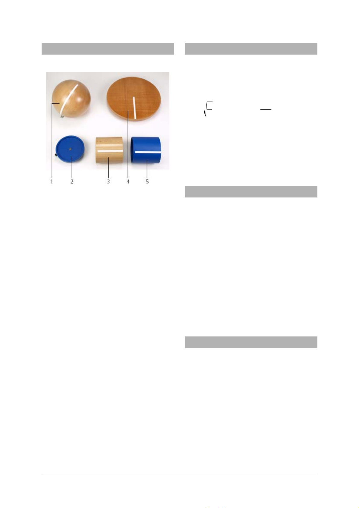
Set of Test Bodies for Torsion Axle U20051
Fig. 1 Set of Test Bodies for Torsion Axle
1 Wooden sphere, 2 Mounting plate, 3 Solid cylinder, 4 Wooden disc, 5 Hollow cylinder
The accessories for the torsion axle (U20050) consist
of two cylinders with nearly identical weights but
different weight distributions, a mounting plate for
the cylinders, a wooden disc and a wooden sphere.
Hollow cylinder (metal):
External diameter: 90 mm
Height: 90 mm
Mass: approx. 425 g
Solid cylinder (wood):
Diameter: 90 mm
Height: 90 mm
Mass: approx. 425 g
Mounting plate:
Diameter: 100 mm
Mass: approx. 122 g
Wooden disc:
Diameter: 220 mm
Height: 15 mm
Mass: approx. 425 g
Moment of inertia: 0.51 kgm
2
Wooden sphere:
Diameter: 146 mm
Mass: approx. 1190 g
Moment of inertia: 0.51 kgm
2
To determine various moments of inertia for different test bodies, these objects are placed on a ballbearing supported shaft which has a coiled spring
attached. The coiled spring is subjected to restoring
torque D. The oscillation period
T
of the torsion
pendulum results in the moment of inertia J.
T π= 2
J
D
D
J ⋅
=
2
4
π
2
T
The values determined experimentally confirm the
findings theoretically postulated for a body of the
mass m, whose mass elements
r
z around a fixed axis:
tance
∑
n
1z
=
2
2
=⋅Δ=
z
z
dmrrmJ
∫
Δm rotate at a dis-
7. Operating notes
• Mount the torsion axle in a tripod stand and
align it horizontally using the spirit level.
• Do not adjust the screws that press the securing
spheres to the rod. (They are adjusted so that the
weights can be moved along the rod but are not
forced outwards by centrifugal forces.)
• Always arrange the experiment so that the spring is
compressed and not extended.
• Start the oscillation by turning the rod 180°
(max. 360°).
• Determine the oscillation period from several
measurements by forming the mean value out of
e.g. 5 oscillations.
• Note down the exact value of the restoring torque
D on the torsion axle or in the operating manual.
This value is used to determine the moment of
inertia J from the oscillation period T.
8. Experiments
To perform the experiments the following apparatus
are required (recommended):
1 Stand Base Tripod, 185 mm U13271
1 Digital Stopwatch U11902
1 Precision Dynamometer 1 N U20032
1 Set of Test Bodies for Torsion Axle U20051
8.1 Determination of the restoring torque D
• Insert the rod without weights onto the torsion axle.
• Attach the 1 N dynamometer to the rod so that it
acts perpendicularly to it.
• At distances of r = 10 cm, 15 cm and 20 cm from
the centre of the rod measure the force F needed
to rotate the rod from its state of equilibrium by
about
α = 180°.
2
Page 3

Torque:
rFM ⋅=
Restoring torque:
=MD
α
8.3.2 Solid cylinder (SC) and hollow cylinder (HC)
• Attach the mounting plate (P) to the torsion axle.
• Determine the moment of inertia J(P).
• Place a cylinder onto the mounting plate (P).
• Determine the moments of inertia J(SC + P) and
J(HC + P).
• Determine the moments of inertia
J(SC) = J(SC + P) – J(P)
J(HC) = J(HC + P) – J(P) by subtracting.
Fig. 2 Determination of the restoring torque
8.2 Dependency of the moment of inertia J on
the distance r, in which a mass m rotates
round a fixed axis
• Attach the rod without weights to the torsion axle.
• Determine the moment of inertia J(rod).
• Arrange the weights at symmetrical distances of
r = 5 cm, 10 cm, 15 cm, 20 cm and 25 cm from
the centre of the rod.
• Determine the moment of inertia J(rod + weights).
• Calculate the moment of inertia J(weights) =
J(rod + weights) – J(rod).
Fig. 3 Dependency of the moment of inertia J on the
distance r
8.3 Comparison of the moments of inertia of
cylinders of the same weight but with
different weight distribution
8.3.1 Wooden disc (WD)
• Attach the wooden disc (WD) to the torsion axle.
• Determine the moment of inertia J(WD).
Fig.4 Determination of the moment of inertia of a
wooden disc
Fig. 5 Comparison of the moments of inertia of cylin-
ders
8.4 Determination of the moment of inertia of a
sphere (S)
• Attach the sphere (S) to the torsion axle.
• Determine the moment of inertia J(S).
A comparison of the sphere with the wooden disc
(refer to 8.3.1.) reveals that they both have the same
moment of inertia. Spheres (S) and wooden discs
(WD) have the same moment of inertia if the following holds true with regard to their mass
R
:
radii
4
)WD()WD( RmRm ⋅=⋅
5
22
)S()S(
Fig. 6 Determination of the moment of inertia of a
sphere
m
and their
8.5 Dependency of the moment of inertia J on
the distance a between the rotation axis and
the axis of the centre of gravity, verification
of Steiner’s theorem
• Attach the round disc to the torsion axle and
align it horizontally.
• Start the disc turning about its centre of gravity
(a = 0).
• Determine the moment of inertia J
• Determine the moments of inertia J
.
0
for different
a
distances of a = 2 cm, 4 cm, 6 cm......16 cm be-
3
Page 4

tween the rotation axis and the axis of the centre
of gravity.
• Re-adjust the horizontal alignment of the disc
after each change of distance a.
JJ
−
• Form the ratios =
Thus Steiner’s theorem
a
2
0a
constant
2
maJJ +=
0a
is verified.
Fig. 7 Verification of Steiner’s theorem
3B Scientific GmbH • Rudorffweg 8 • 21031 Hamburg • Germany • www.3bscientific.com
Subject to technical amendments
© Copyright 2011 3B Scientific GmbH
 Loading...