

Page 1

Meridian 1
Meridian Internet Telephony Gateway
(ITG) Trunk 2.0/ISDN Signaling Link (ISL)
Description, Installation and Operation
Document Number: 553-3001-202
Document Release: Standard 1.00
Date: April 2000
Year Publish FCC TM
Copyright © 2000 Nortel Networks
All Rights Rese rved
Printed in Canada
Information is subject to change without notice. Nortel Networks reserves the right to make changes in design
or comp onents as progress in engineering and manufacturing may warrant. This equipment has been tested
and f ound to comply with the limits for a Class A digital device pursuant to P art 15 of the FCC rules, and the
radio interference regulations of Industry Canada. These limits are designed to provide reasonable protection
against harmful interference when the equipment is operated in a commercial environmen t. This equipment
generates, uses and can radiate radio fr equency energy, and if not installed and used in accordance with the
instruction manual, may cause harmful interference to radio communications. Operation of this equipment in a
residential area is likely to cause harmf ul interference in which case the user will be required to correct the
interference at their own expense.
SL-1 and Meridian1 are trademarks of Nortel Networks.
ITG Trunk 2.0 ISDN Signaling Link (ISL) Descriptio n, Installation and Operation
Page 2

Page 3

4
Revision history
April 2000
Standard, releas e 1.00. This is a global document and is issued for X11
Release 25.0x.
Page 3 of
378
ITG Trunk 2.0 ISDN Signaling Link (ISL) Description, Installation and Operation
Page 4

Page 4 of
378
553-3001-202 Standard 1.00 April 2000
Page 5

16
Contents
Page 5 of
378
About this guide . . . . . . . . . . . . . . . . . . . . . . . . . . . 17
Description . . . . . . . . . . . . . . . . . . . . . . . . . . . . . . . . 19
System requirements . . . . . . . . . . . . . . . . . . . . . . . . . . . . . . . . . . . . . . 21
List of ITG ISDN components . . . . . . . . . . . . . . . . . . . . . . . . . . . . . . . 23
Ordering rules and guidelines . . . . . . . . . . . . . . . . . . . . . . . . . . . . . . . 26
Ordering rules for ITG ISL Trunk node initial configuration . . . . . 26
Ordering rules for ITG ISL Trunk node expansion . . . . . . . . . . . . . 27
Sparing ratios for ITG Trunk components . . . . . . . . . . . . . . . . . . . 28
ITG ISL Trunk card description . . . . . . . . . . . . . . . . . . . . . . . . . . . . . . 28
Card roles . . . . . . . . . . . . . . . . . . . . . . . . . . . . . . . . . . . . . . . . . . . . . 28
Card combinations . . . . . . . . . . . . . . . . . . . . . . . . . . . . . . . . . . . . . . 33
Interactions among card functions . . . . . . . . . . . . . . . . . . . . . . . . . . 34
ITG ISL Trunk card physical description . . . . . . . . . . . . . . . . . . . . . . 37
Faceplate indicators, controls, and interfaces . . . . . . . . . . . . . . . . . 39
Backplane interfaces . . . . . . . . . . . . . . . . . . . . . . . . . . . . . . . . . . . . 42
Assembly description . . . . . . . . . . . . . . . . . . . . . . . . . . . . . . . . . . . 42
ISDN Signaling Link . . . . . . . . . . . . . . . . . . . . . . . . . . . . . . . . . . . . . . 44
Inter-card signaling paths . . . . . . . . . . . . . . . . . . . . . . . . . . . . . . . . 47
Dialing plans . . . . . . . . . . . . . . . . . . . . . . . . . . . . . . . . . . . . . . . . . . . . 49
Multi-node configuration . . . . . . . . . . . . . . . . . . . . . . . . . . . . . . . . . 49
North American dialing plan . . . . . . . . . . . . . . . . . . . . . . . . . . . . . . 50
Flexible Numbering Plan . . . . . . . . . . . . . . . . . . . . . . . . . . . . . . . . . 51
Electronic Switc hed Network (ESN) Network Signaling . . . . . . . . 51
Echo cancellation . . . . . . . . . . . . . . . . . . . . . . . . . . . . . . . . . . . . . . . 52
Silence Suppression . . . . . . . . . . . . . . . . . . . . . . . . . . . . . . . . . . . . . 52
ITG Trunk 2.0 ISDN Signaling Link (ISL) Description, Installation and Operation
Page 6

Page 6 of
378
Contents
DTMF Through Dial . . . . . . . . . . . . . . . . . . . . . . . . . . . . . . . . . . . . 52
Quality of Service . . . . . . . . . . . . . . . . . . . . . . . . . . . . . . . . . . . . . . . . 53
Quality of Service parameters . . . . . . . . . . . . . . . . . . . . . . . . . . . . . 54
Network performance utilities . . . . . . . . . . . . . . . . . . . . . . . . . . . . 55
E-Model . . . . . . . . . . . . . . . . . . . . . . . . . . . . . . . . . . . . . . . . . . . . . 56
Fallback to alternate facilities . . . . . . . . . . . . . . . . . . . . . . . . . . . . . . . 57
Triggering F allback to alternate trunk facilities . . . . . . . . . . . . . . . 57
Return to the IP network . . . . . . . . . . . . . . . . . . . . . . . . . . . . . . . . . 58
Type of Service . . . . . . . . . . . . . . . . . . . . . . . . . . . . . . . . . . . . . . . . . . 59
Fax support . . . . . . . . . . . . . . . . . . . . . . . . . . . . . . . . . . . . . . . . . . . . . 61
Remote Access . . . . . . . . . . . . . . . . . . . . . . . . . . . . . . . . . . . . . . . . . . . 62
Per-call statistics support using RADIUS Client . . . . . . . . . . . . . . . . . 63
Configuration . . . . . . . . . . . . . . . . . . . . . . . . . . . . . . . . . . . . . . . . . 64
Messaging . . . . . . . . . . . . . . . . . . . . . . . . . . . . . . . . . . . . . . . . . . . . 64
SNMP MIB . . . . . . . . . . . . . . . . . . . . . . . . . . . . . . . . . . . . . . . . . . . . . 66
MIB-2 support . . . . . . . . . . . . . . . . . . . . . . . . . . . . . . . . . . . . . . . . . 66
ITG SNMP agent . . . . . . . . . . . . . . . . . . . . . . . . . . . . . . . . . . . . . . 66
Codec profiles . . . . . . . . . . . . . . . . . . . . . . . . . . . . . . . . . . . . . . . . . . . 68
G.711 . . . . . . . . . . . . . . . . . . . . . . . . . . . . . . . . . . . . . . . . . . . . . . . . 68
G.729A . . . . . . . . . . . . . . . . . . . . . . . . . . . . . . . . . . . . . . . . . . . . . . 68
G.729 . . . . . . . . . . . . . . . . . . . . . . . . . . . . . . . . . . . . . . . . . . . . . . . . 69
G.723.1 (5.3 kbit/s or 6.3 kbit/s) . . . . . . . . . . . . . . . . . . . . . . . . . . . 69
Security passwords . . . . . . . . . . . . . . . . . . . . . . . . . . . . . . . . . . . . . . . 70
Administrator level . . . . . . . . . . . . . . . . . . . . . . . . . . . . . . . . . . . . . 70
Technical su pport level . . . . . . . . . . . . . . . . . . . . . . . . . . . . . . . . . . 70
ITG Engineering Guidelines . . . . . . . . . . . . . . . . . 71
Introduction . . . . . . . . . . . . . . . . . . . . . . . . . . . . . . . . . . . . . . . . . . . . . 71
Audience . . . . . . . . . . . . . . . . . . . . . . . . . . . . . . . . . . . . . . . . . . . . . 72
ITG equipment requirements . . . . . . . . . . . . . . . . . . . . . . . . . . . . . 72
Scope . . . . . . . . . . . . . . . . . . . . . . . . . . . . . . . . . . . . . . . . . . . . . . . . 73
Network engineering guidelines overview . . . . . . . . . . . . . . . . . . . . . 74
ITG traffic engineering . . . . . . . . . . . . . . . . . . . . . . . . . . . . . . . . . . . . 76
Use of Ethernet and WAN bandwidth . . . . . . . . . . . . . . . . . . . . . . 76
553-3001-202 Standard 1.00 April 2000
Page 7

Contents Page 7 of
378
Disable silence suppression at tandem nodes . . . . . . . . . . . . . . . . . 78
Simultaneous voice traffic with silence suppression . . . . . . . . . . . . 79
T-LAN traffic calculations . . . . . . . . . . . . . . . . . . . . . . . . . . . . . . . 81
General LAN and WAN engineering consi derations . . . . . . . . . . . 84
Fax engineering considerations . . . . . . . . . . . . . . . . . . . . . . . . . . . . 85
Configuration of Meridian 1 routes and network tr anslation . . . . . . . . 86
Configure the IP router on the T-LAN . . . . . . . . . . . . . . . . . . . . . . 87
Leader And DCHIP Card Real Time Engineering . . . . . . . . . . . . . 88
Provisioning ITG ISL TIE tr unks and routes . . . . . . . . . . . . . . . . . 94
WAN route engineering . . . . . . . . . . . . . . . . . . . . . . . . . . . . . . . . . 97
Assess WAN link resources . . . . . . . . . . . . . . . . . . . . . . . . . . . . . . . . . 101
Link utilization . . . . . . . . . . . . . . . . . . . . . . . . . . . . . . . . . . . . . . . . 101
Estimate network loading caused by ITG traffic . . . . . . . . . . . . . . . 102
Route Link Traffic Estimation . . . . . . . . . . . . . . . . . . . . . . . . . . . . . 104
Decision: Enough capaci ty? . . . . . . . . . . . . . . . . . . . . . . . . . . . . . . 106
Insufficient link capacity . . . . . . . . . . . . . . . . . . . . . . . . . . . . . . . . . 107
Other intranet resource considerations . . . . . . . . . . . . . . . . . . . . . . 107
QoS Evaluation Process Overview . . . . . . . . . . . . . . . . . . . . . . . . . . . 108
Set QoS . . . . . . . . . . . . . . . . . . . . . . . . . . . . . . . . . . . . . . . . . . . . . . . . . 108
Measure intranet QoS . . . . . . . . . . . . . . . . . . . . . . . . . . . . . . . . . . . . . . 114
Measure end-to-end network delay . . . . . . . . . . . . . . . . . . . . . . . . . 114
Measure end-to-end packet loss . . . . . . . . . . . . . . . . . . . . . . . . . . . 115
Adjust ping measurements . . . . . . . . . . . . . . . . . . . . . . . . . . . . . . . 116
Network delay and packe t los s evaluation example . . . . . . . . . . . . 116
Other measurement considerations . . . . . . . . . . . . . . . . . . . . . . . . . 118
Obtain QoS measurement tools . . . . . . . . . . . . . . . . . . . . . . . . . . . . 118
Decision: does t h e intranet meet expected ITG QoS? . . . . . . . . . . . 118
Fine-tune Network QoS . . . . . . . . . . . . . . . . . . . . . . . . . . . . . . . . . . 119
Components of delay . . . . . . . . . . . . . . . . . . . . . . . . . . . . . . . . . . . . 119
Reduce link delay . . . . . . . . . . . . . . . . . . . . . . . . . . . . . . . . . . . . . . 122
Reduce hop count . . . . . . . . . . . . . . . . . . . . . . . . . . . . . . . . . . . . . . 124
Adjust jitter buffer size . . . . . . . . . . . . . . . . . . . . . . . . . . . . . . . . . . 124
Reduce packet errors . . . . . . . . . . . . . . . . . . . . . . . . . . . . . . . . . . . . 124
Routing issues . . . . . . . . . . . . . . . . . . . . . . . . . . . . . . . . . . . . . . . . . 125
Network modeling . . . . . . . . . . . . . . . . . . . . . . . . . . . . . . . . . . . . . . 125
ITG Trunk 2.0 ISDN Signaling Link (ISL) Description, Installation and Operation
Page 8

Page 8 of
378
Contents
Implement QoS in IP networks . . . . . . . . . . . . . . . . . . . . . . . . . . . . . . 126
Traffic mix . . . . . . . . . . . . . . . . . . . . . . . . . . . . . . . . . . . . . . . . . . . 126
TCP traffic behavior . . . . . . . . . . . . . . . . . . . . . . . . . . . . . . . . . . . . 127
ITG support for TOS field and IP QoS . . . . . . . . . . . . . . . . . . . . . . 127
Queue management . . . . . . . . . . . . . . . . . . . . . . . . . . . . . . . . . . . . . 128
Use of Frame Relay and ATM services . . . . . . . . . . . . . . . . . . . . . 129
Internet Protocols and Ports Used by ITG . . . . . . . . . . . . . . . . . . . 129
ITG ISL Trunk card connections . . . . . . . . . . . . . . . . . . . . . . . . . . 129
Set up a system with separate subnets for voice and managem ent . 130
Subnet configurations . . . . . . . . . . . . . . . . . . . . . . . . . . . . . . . . . . . 131
Single subnet option for voice and management . . . . . . . . . . . . . . 131
Multiple ITG nodes on the same E-LAN and T-LAN segments . . 132
Setting up the E-LAN or management s ubnet . . . . . . . . . . . . . . . . 132
Selecting public or private IP addresses . . . . . . . . . . . . . . . . . . . . . 132
T-LAN engineering . . . . . . . . . . . . . . . . . . . . . . . . . . . . . . . . . . . . . 133
Setting the Quality of Service threshold for fallback routing . . . . . 134
Basic setup of the ITG system . . . . . . . . . . . . . . . . . . . . . . . . . . . . 134
ITG Trunk DSP profile settings . . . . . . . . . . . . . . . . . . . . . . . . . . . . . . 135
Codec types . . . . . . . . . . . . . . . . . . . . . . . . . . . . . . . . . . . . . . . . . . . 135
Fall back threshold . . . . . . . . . . . . . . . . . . . . . . . . . . . . . . . . . . . . . 136
Payload size . . . . . . . . . . . . . . . . . . . . . . . . . . . . . . . . . . . . . . . . . . . 136
Silence suppres s ion parameters (Voice activity detection) . . . . . . . 137
Jitter buffer parameters (Voice playout delay) . . . . . . . . . . . . . . . . 137
Post-installation network measurements . . . . . . . . . . . . . . . . . . . . . . . 138
Set ITG QoS objectives . . . . . . . . . . . . . . . . . . . . . . . . . . . . . . . . . . 139
Intranet QoS monitoring . . . . . . . . . . . . . . . . . . . . . . . . . . . . . . . . . 140
ITG network inventory and configuration . . . . . . . . . . . . . . . . . . . 141
User feedback . . . . . . . . . . . . . . . . . . . . . . . . . . . . . . . . . . . . . . . . . 141
Estimate QoS level . . . . . . . . . . . . . . . . . . . . . . . . . . . . . . . . . . . . . . . . 143
ITG MAT PC management configuration . . . . . . . 147
MAT ITG Engineering rules . . . . . . . . . . . . . . . . . . . . . . . . . . . . . . . . 147
MAT network setup guidelines . . . . . . . . . . . . . . . . . . . . . . . . . . . . . . 148
MAT Remote Access configuration . . . . . . . . . . . . . . . . . . . . . . . . . . 148
MAT PC description . . . . . . . . . . . . . . . . . . . . . . . . . . . . . . . . . . . . . . 149
553-3001-202 Standard 1.00 April 2000
Page 9

Contents Page 9 of
378
MAT PC hardware and software requirements . . . . . . . . . . . . . . . . . . 151
Hard drive requirements . . . . . . . . . . . . . . . . . . . . . . . . . . . . . . . . . 152
Install and configure ITG ISL Trunk node . . . . . . . 153
Before you begin . . . . . . . . . . . . . . . . . . . . . . . . . . . . . . . . . . . . . . . . . 153
Installation Procedure Summary . . . . . . . . . . . . . . . . . . . . . . . . . . . . . 154
Create the ITG Trunk Installation Summary Shee t . . . . . . . . . . . . . . . 156
Install and cabl e IT G tr unk cards . . . . . . . . . . . . . . . . . . . . . . . . . . . . . 158
Card installation procedure . . . . . . . . . . . . . . . . . . . . . . . . . . . . . . . 158
Install NTCW84JA Large System I/O Panel 50-Pin filter adapte r . . . 161
Remove existing I/O panel filter adapter . . . . . . . . . . . . . . . . . . . . . 162
Install NTMF94EA and NTCW84KA cables . . . . . . . . . . . . . . . . . . . 164
Install the NTCW84KA cable (for DCHIP cards) . . . . . . . . . . . . . 164
Install the NTMF94EA cable (for non-DCHIP cards) . . . . . . . . . . 166
Install shielded voice interface (T-LAN) cable . . . . . . . . . . . . . . . . 167
Install shielded management interface (E-LAN) cable . . . . . . . . . . 167
D-channel cabling for the NT0961AA 24-Port ITG Trunk card . . . . . 168
Large systems required cables and filters . . . . . . . . . . . . . . . . . . . . 168
Set NT6D80 MSDL switches . . . . . . . . . . . . . . . . . . . . . . . . . . . . . . . . 168
Install filter and NTND26 cable (for MSDL and DCHIP
cards in same Large System equipment row) . . . . . . . . . . . . . . . . . . . . 169
Install filter and NTND26 cable (for MSDL and DCHIP
cards in different Large System equipment rows) . . . . . . . . . . . . . . . . 171
Meridian 1 Small System cable installation (Option 11C and
Option 11C Mini) . . . . . . . . . . . . . . . . . . . . . . . . . . . . . . . . . . . . . . 172
Install the serial cable . . . . . . . . . . . . . . . . . . . . . . . . . . . . . . . . . . . 173
Configure ITG Trunk data on the Meridian 1 . . . . . . . . . . . . . . . . . . . 174
Configure the ISL D-ch annel on the Meridian 1 for the
DCHIP card . . . . . . . . . . . . . . . . . . . . . . . . . . . . . . . . . . . . . . . . . . . 174
Configure ISDN feature in customer data block . . . . . . . . . . . . . . . 178
Configure ITG ISL TIE trunk rout es . . . . . . . . . . . . . . . . . . . . . . . . 178
Configure ITG ISL trunk cards and units . . . . . . . . . . . . . . . . . . . . 182
Configure dialing plans within the corporate network . . . . . . . . . . . . . 185
ITG Trunk 2.0 ISDN Signaling Link (ISL) Description, Installation and Operation
Page 10

Page 10 of
378
Contents
Make the ITG the first-choice, least-cost entry in the
route list block . . . . . . . . . . . . . . . . . . . . . . . . . . . . . . . . . . . . . . . . . 185
Turn on Step Back on Congestion (SBOC) for the
ITG Trunk route . . . . . . . . . . . . . . . . . . . . . . . . . . . . . . . . . . . . . . . 185
Turn off ITG route during peak traffic periods on the
IP data network . . . . . . . . . . . . . . . . . . . . . . . . . . . . . . . . . . . . . . . . 186
ESN5 network signaling . . . . . . . . . . . . . . . . . . . . . . . . . . . . . . . . . 186
Disable the ITG Trunk cards . . . . . . . . . . . . . . . . . . . . . . . . . . . . . . 191
Configure ITG Trunk data on MAT . . . . . . . . . . . . . . . . . . . . . . . . . . 191
Add an ITG Trunk node on MAT manually . . . . . . . . . . . . . . . . . . 192
Add a node and configure general node properties . . . . . . . . . . . . . 192
Set node locati on properties . . . . . . . . . . . . . . . . . . . . . . . . . . . . . . 192
Single vs. separate subnets for T-LAN and E-LAN . . . . . . . . . . . . 193
Configure Network Connections . . . . . . . . . . . . . . . . . . . . . . . . . . 194
Configure card properties . . . . . . . . . . . . . . . . . . . . . . . . . . . . . . . . 195
Configure DSP profiles for the ITG Trunk node . . . . . . . . . . . . . . 199
Configure SNMP Traps/Routing and IPs tab . . . . . . . . . . . . . . . . . 204
Configure Account ing server . . . . . . . . . . . . . . . . . . . . . . . . . . . . . 205
Set Security for MAT SNMP access . . . . . . . . . . . . . . . . . . . . . . . . 207
Exit node property configuration session . . . . . . . . . . . . . . . . . . . . 208
Create the ITG Trunk node dialing plan usi ng MAT . . . . . . . . . . . 208
Retrieve the ITG Trunk node dialing pl an us ing MAT . . . . . . . . . 213
Transmit ITG trunk card configuration data from
MAT to the ITG trunk cards . . . . . . . . . . . . . . . . . . . . . . . . . . . . . . . . 215
Before you can transmit configuration data . . . . . . . . . . . . . . . . . . 215
Setting the Leader 0 IP address . . . . . . . . . . . . . . . . . . . . . . . . . . . . 216
Transmit the node properties, card properties and
dialing plan to Leader 0 . . . . . . . . . . . . . . . . . . . . . . . . . . . . . . . . . 218
Verify installation and configuration . . . . . . . . . . . . . . . . . . . . . . . 219
Observe ITG ISL trunk status in MAT . . . . . . . . . . . . . . . . . . . . . . 219
Transm it Card Properties an d Dialing Plan to Le ad er 1
and Follower cards . . . . . . . . . . . . . . . . . . . . . . . . . . . . . . . . . . . . . 220
Set date and time for the ITG ISL Trunk node . . . . . . . . . . . . . . . . . . 222
Change the default ITG shell password to maintai n ac cess security . . 222
Change default ESN5 prefix for non-ESN5 IP telephony gateways . . 223
553-3001-202 Standard 1.00 April 2000
Page 11

Contents Page 11 of
Check card software . . . . . . . . . . . . . . . . . . . . . . . . . . . . . . . . . . . . . . . 225
Transmit new software to ITG Trunk c ards . . . . . . . . . . . . . . . . . . 227
Upgrade the DCHIP PC Card . . . . . . . . . . . . . . . . . . . . . . . . . . . . . 229
Configure MAT Alarm Manag em ent to receive SNMP
traps from ITG ISL Trunk cards . . . . . . . . . . . . . . . . . . . . . . . . . . . . . 231
Make test calls to the remote ITG nodes . . . . . . . . . . . . . . . . . . . . . . . 234
378
Upgrade an ITG Trunk 1.0 node to support ISDN
signaling trunks . . . . . . . . . . . . . . . . . . . . . . . . . . . . 235
Upgrade procedure summary . . . . . . . . . . . . . . . . . . . . . . . . . . . . . . . . 235
Before you begin . . . . . . . . . . . . . . . . . . . . . . . . . . . . . . . . . . . . . . . . . 236
Install the DCHIP hardware upgra de kit . . . . . . . . . . . . . . . . . . . . . . . 237
Install the DCHIP I/O Panel breakout cable from the upgrade kit . 239
Upgrade the 8-port ITG basic trunk software to
ITG ISL trunk software . . . . . . . . . . . . . . . . . . . . . . . . . . . . . . . . . . . . 239
Step 1 - Remove ITG 1.0 configuration files . . . . . . . . . . . . . . . . . 240
Step 2 - Transmit ITG Trunk 2.0 software to the 8-port cards . . . . 241
Remove ITG 1.0 configu r ation data from Meridian 1 . . . . . . . . . . . . . 243
Configure the Meri dian 1 ITG ISL Trunk data:
upgrade considerations . . . . . . . . . . . . . . . . . . . . . . . . . . . . . . . . . . . . . 244
Verify ROM-BIOS version . . . . . . . . . . . . . . . . . . . . . . . . . . . . . . . . . 245
Upgrade Troubleshooting . . . . . . . . . . . . . . . . . . . . . . . . . . . . . . . . . . . 245
MAT cannot refresh vie w ( Card not responding) . . . . . . . . . . . . . . 245
How to upgrade software using the ITG shell . . . . . . . . . . . . . . . . . 246
OA&M using MAT applications . . . . . . . . . . . . . . . 247
MAT OA&M procedure summary . . . . . . . . . . . . . . . . . . . . . . . . . . . . 247
Delete a node . . . . . . . . . . . . . . . . . . . . . . . . . . . . . . . . . . . . . . . . . . 248
Database locking . . . . . . . . . . . . . . . . . . . . . . . . . . . . . . . . . . . . . . . 249
ITG Card Properties . . . . . . . . . . . . . . . . . . . . . . . . . . . . . . . . . . . . 250
ITG Card Properties – Maintenance window . . . . . . . . . . . . . . . . . 250
ITG Card Properties – Confi guration window . . . . . . . . . . . . . . . . 252
DSP maintenance window . . . . . . . . . . . . . . . . . . . . . . . . . . . . . . . . 252
D-channel maintenance . . . . . . . . . . . . . . . . . . . . . . . . . . . . . . . . . . 253
ITG Trunk 2.0 ISDN Signaling Link (ISL) Description, Installation and Operation
Page 12

Page 12 of
378
Contents
Add Dialing Plan entries . . . . . . . . . . . . . . . . . . . . . . . . . . . . . . . . . 254
Transmit configuration data . . . . . . . . . . . . . . . . . . . . . . . . . . . . . . 259
Add an ITG ISL Trunk node on MAT by retrieving an e xisting node 262
Retrieve and add an ITG ISL Trunk Node f or
administration purposes . . . . . . . . . . . . . . . . . . . . . . . . . . . . . . . . . 263
Retrieve and add an ITG ISL Trunk Node for maintenance
and diagnostic purposes . . . . . . . . . . . . . . . . . . . . . . . . . . . . . . . . . . . . 265
Configuration audit . . . . . . . . . . . . . . . . . . . . . . . . . . . . . . . . . . . . . 266
Retrieve ITG configuration information from the ITG node . . . . . 266
Schedule and generate and view ITG OM reports . . . . . . . . . . . . . 268
Backup and restore operations . . . . . . . . . . . . . . . . . . . . . . . . . . . . 268
Alarm Notification . . . . . . . . . . . . . . . . . . . . . . . . . . . . . . . . . . . . . 269
Meridian 1 system commands - LD 32 . . . . . . . . . . . . . . . . . . . . . . . . 270
Disable the indicated ITG card . . . . . . . . . . . . . . . . . . . . . . . . . . . . 272
Disable the indicated ITG card when idle . . . . . . . . . . . . . . . . . . . . 273
Disable an indicated ITG port . . . . . . . . . . . . . . . . . . . . . . . . . . . . . 273
Enable an indicated ITG card . . . . . . . . . . . . . . . . . . . . . . . . . . . . . 273
Enable an indicated ITG port . . . . . . . . . . . . . . . . . . . . . . . . . . . . . 273
Display ITG card ID information . . . . . . . . . . . . . . . . . . . . . . . . . . 274
Display ITG card status . . . . . . . . . . . . . . . . . . . . . . . . . . . . . . . . . . 274
Display ITG card port status . . . . . . . . . . . . . . . . . . . . . . . . . . . . . . 274
OA&M using the ITG shell CLI and overlays . . . . 275
ITG Shell OA&M procedure summary . . . . . . . . . . . . . . . . . . . . . . . . 275
Access the ITG shell through a maintenance port or Telnet . . . . . . . . 276
Connect a PC to card maintenance port . . . . . . . . . . . . . . . . . . . . . 276
Telnet to an ITG card through the MAT PC . . . . . . . . . . . . . . . . . . 277
Change the default ITG shell password to maintai n access security 278
Reset the default ITG shell password . . . . . . . . . . . . . . . . . . . . . . . 279
Down lo ad th e ITG o pe r at io nal mea su r ements
through the ITG shell . . . . . . . . . . . . . . . . . . . . . . . . . . . . . . . . . . . 280
Reset the operational measurements . . . . . . . . . . . . . . . . . . . . . . . . 281
Display the number of DSPs . . . . . . . . . . . . . . . . . . . . . . . . . . . . . . 281
Display ITG Node Properties . . . . . . . . . . . . . . . . . . . . . . . . . . . . . 281
Transfer files through the command line interface . . . . . . . . . . . . . 282
Upgrade ITG card software from the command line interface . . . . 284
553-3001-202 Standard 1.00 April 2000
Page 13

Contents Page 13 of
378
Backup and restore from th e ITG command line interface . . . . . . . 287
Recover the SNMP community names . . . . . . . . . . . . . . . . . . . . . . 288
IP configuration commands . . . . . . . . . . . . . . . . . . . . . . . . . . . . . . . 288
Download the ITG error log . . . . . . . . . . . . . . . . . . . . . . . . . . . . . . 289
Meridian 1 system commands - LD 32 . . . . . . . . . . . . . . . . . . . . . . . . 289
Disable the indicated ITG card . . . . . . . . . . . . . . . . . . . . . . . . . . . . 291
Disable the indicated ITG card when idle . . . . . . . . . . . . . . . . . . . . 291
Disable an indicated ITG port . . . . . . . . . . . . . . . . . . . . . . . . . . . . . 291
Enable an indicated ITG card . . . . . . . . . . . . . . . . . . . . . . . . . . . . . 292
Enable an indicated ITG port . . . . . . . . . . . . . . . . . . . . . . . . . . . . . 292
Display ITG card ID information . . . . . . . . . . . . . . . . . . . . . . . . . . 292
Display ITG card status . . . . . . . . . . . . . . . . . . . . . . . . . . . . . . . . . . 292
Display ITG card port status . . . . . . . . . . . . . . . . . . . . . . . . . . . . . . 293
Maintenance . . . . . . . . . . . . . . . . . . . . . . . . . . . . . . . 295
ITG Trunk 2.0 alarms . . . . . . . . . . . . . . . . . . . . . . . . . . . . . . . . . . . . . . 296
System level maintenance . . . . . . . . . . . . . . . . . . . . . . . . . . . . . . . . . . 302
Access the ITG card . . . . . . . . . . . . . . . . . . . . . . . . . . . . . . . . . . . . 303
ITG card overlay commands . . . . . . . . . . . . . . . . . . . . . . . . . . . . . . 303
MAT maintenance commands . . . . . . . . . . . . . . . . . . . . . . . . . . . . . 305
Multi-purpose Serial Data Link (MSDL) commands . . . . . . . . . . . 305
Simple Network Management Protocol (SNMP) . . . . . . . . . . . . . . 306
TRACE and ALARM/LOG . . . . . . . . . . . . . . . . . . . . . . . . . . . . . . 307
ITG shell command set . . . . . . . . . . . . . . . . . . . . . . . . . . . . . . . . . . . . 307
ITG card self-tests . . . . . . . . . . . . . . . . . . . . . . . . . . . . . . . . . . . . . . . . 317
Card LAN . . . . . . . . . . . . . . . . . . . . . . . . . . . . . . . . . . . . . . . . . . . . 318
BIOS self-test . . . . . . . . . . . . . . . . . . . . . . . . . . . . . . . . . . . . . . . . . 318
Base code self-test . . . . . . . . . . . . . . . . . . . . . . . . . . . . . . . . . . . . . . 318
Field-Programmable Gate Array (FPGA) testing . . . . . . . . . . . . . . 318
Upgrades . . . . . . . . . . . . . . . . . . . . . . . . . . . . . . . . . . . . . . . . . . . . . . . . 318
Application upgrade . . . . . . . . . . . . . . . . . . . . . . . . . . . . . . . . . . . . 319
Maintenance or bug fix upgrade . . . . . . . . . . . . . . . . . . . . . . . . . . . 319
Capacity upgra des . . . . . . . . . . . . . . . . . . . . . . . . . . . . . . . . . . . . . . 319
Flash storage upgrades . . . . . . . . . . . . . . . . . . . . . . . . . . . . . . . . . . 319
Protocol table upgrade . . . . . . . . . . . . . . . . . . . . . . . . . . . . . . . . . . . 319
ITG Trunk 2.0 ISDN Signaling Link (ISL) Description, Installation and Operation
Page 14

Page 14 of
378
Contents
Software upgrade mechanisms . . . . . . . . . . . . . . . . . . . . . . . . . . . . 319
Replace an I TG card . . . . . . . . . . . . . . . . . . . . . . . . . . . . . . . . . . . . . . 321
Check card software . . . . . . . . . . . . . . . . . . . . . . . . . . . . . . . . . . . . 324
Transmit card properties and dialing plan . . . . . . . . . . . . . . . . . . . . 325
Backup and restore procedures . . . . . . . . . . . . . . . . . . . . . . . . . . . . . . 325
ITG card . . . . . . . . . . . . . . . . . . . . . . . . . . . . . . . . . . . . . . . . . . . . . 325
MAT . . . . . . . . . . . . . . . . . . . . . . . . . . . . . . . . . . . . . . . . . . . . . . . . 326
Command line interface . . . . . . . . . . . . . . . . . . . . . . . . . . . . . . . . . 326
Fault clearance procedures . . . . . . . . . . . . . . . . . . . . . . . . . . . . . . . . . . 326
DSP failure . . . . . . . . . . . . . . . . . . . . . . . . . . . . . . . . . . . . . . . . . . . 326
Card failure . . . . . . . . . . . . . . . . . . . . . . . . . . . . . . . . . . . . . . . . . . . 327
DCH failure . . . . . . . . . . . . . . . . . . . . . . . . . . . . . . . . . . . . . . . . . . . 327
ITG Trunk 2.0 faceplate maintenance display codes . . . . . . . . . . . . . . 329
Appendix A: Cable description and
NT8D81BA cable replacement . . . . . . . . . . . . . . . . 333
NTMF94EA E - LAN, T - LAN and Serial Port cable . . . . . . . . . . . . 333
NTCW84KA E-LAN, T-LAN, DCH & Serial cable . . . . . . . . . . . . . . 336
NTAG81CA Faceplate Maintenance cable . . . . . . . . . . . . . . . . . . . . . 338
NTAG81BA Maintenance Extender cable . . . . . . . . . . . . . . . . . . . . . 340
NTCW84EA DCH PC Card Pigtail cable . . . . . . . . . . . . . . . . . . . . . . 341
NTMF04BA MSDL extension cable . . . . . . . . . . . . . . . . . . . . . . . . . . 343
NTCW84LA and NTCW84MA upgrade cables . . . . . . . . . . . . . . . . . 345
Prevent ground loops on connection to external
customer LAN equipment . . . . . . . . . . . . . . . . . . . . . . . . . . . . . . . . . . 349
Replace cable NT8D81BA with NT8D81AA . . . . . . . . . . . . . . . . . . . 350
Tools list . . . . . . . . . . . . . . . . . . . . . . . . . . . . . . . . . . . . . . . . . . . . . . . 351
NT8D81BA cable removal procedures . . . . . . . . . . . . . . . . . . . . . . . . 351
Install NTCW84JA filter and NT8D81AA cable . . . . . . . . . . . . . . 352
Appendix B: Environmental and
electrical regulatory data . . . . . . . . . . . . . . . . . . . . 353
Environmental specifications . . . . . . . . . . . . . . . . . . . . . . . . . . . . . . . . 353
553-3001-202 Standard 1.00 April 2000
Page 15

Contents Page 15 of
Mechanical conditions . . . . . . . . . . . . . . . . . . . . . . . . . . . . . . . . . . . 354
Electrical regulatory standards . . . . . . . . . . . . . . . . . . . . . . . . . . . . . . . 355
Safety . . . . . . . . . . . . . . . . . . . . . . . . . . . . . . . . . . . . . . . . . . . . . . . . 355
Electromagnetic Compatibility (EMC) . . . . . . . . . . . . . . . . . . . . . . 355
378
Appendix C: Subnet mask conversion
from CIDR to dotted decimal format . . . . . . . . . . . 357
Appendix D: Configure a Netgear RM356
modem router for remote access . . . . . . . . . . . . . 359
Security features of the RM356 modem router . . . . . . . . . . . . . . . . 359
Install the RM356 mod em r outer . . . . . . . . . . . . . . . . . . . . . . . . . . 360
Configure the MAT ITG PC to communic ate with a
remote Meridian 1 site via modem router . . . . . . . . . . . . . . . . . . . . 361
Configure the RM356 m odem router by the manager menu . . . . . . 361
RM356 modem router manager menu
(applicat ion notes on Meridian 1 E-LAN instal lation) . . . . . . . . . . 366
Index . . . . . . . . . . . . . . . . . . . . . . . . . . . . . . . . . . . . . 375
ITG Trunk 2.0 ISDN Signaling Link (ISL) Description, Installation and Operation
Page 16

Page 16 of
378
Contents
553-3001-202 Standard 1.00 April 2000
Page 17

18
About this guide
This document is a global document. Contact your s ystem supplier or your
Nortel Networks representative to verify that the hardware and software
described is suppo rted in your area.
This guide describes and explains how to engine er, install, configure,
administer and maintain a Meridian Internet Telephony Gateway (ITG)
Trunk 2.0 system.
The ITG Trunk 2.0 compresses PCM voice, demodulat es Group 3 fax, routes
the packetized data over a private internet, or intranet and provides virtual
analog ISDN signalli ng link (ISL) TIE trunks between Meridia n 1 ESN
nodes.
ITG Trunk 2.0 routes voice traffic over existing private IP network facilities
with available und er-us ed bandwidth on the private Wide Area network
(WAN) backbone.
Page 17 of
378
ITG Trunk 2.0 ISDN Signaling Link (ISL) Description, Installation and Operation
Page 18

Page 18 of
378
About this guide
553-3001-202 Standard 1.00 April 2000
Page 19

70
Description
The Meridian Internet Telephony Gateway (ITG) Trunk 2.0 suppor ts ISDN
Signaling Link (ISL) IP trunks on the NT0961 24-port Meridian Internet
Telephony Gateway (ITG) trunk card. It also supports ISL IP Trunks on the
NTCW80 8-port ITG 1.0 trunk card that have been upgraded with IT G Trunk
2.0 software and hardware.
An ISDN Signaling Link D-channel (ISL DCH) provides DCH connectivity
to the Meridian 1 and signaling control for the 24 ports on the card and any
additional ports on other ITG Trunk cards in the same node. The DCH
connection expands the signaling path between the Meridian 1 and the
gateway. I TG all ows Meridi an 1 systems to b e net worke d usi ng I SDN, while
transmitting H.323 signaling and voice over a standard IP protocol st ac k.
The ITG ISL Trunk compresses voice and demodulates Group 3 Fax. ITG
then routes the packetized data over a pr ivate IP n etwork for co nnections
between Meridian 1 nodes, bypassing circu it-switched trunking facilities.
The ITG ISL Trunk delivers an ISDN signaling interface between the
Meridian 1 and the Voice and Fax over IP (VoIP) interface. The high
signaling bandwi dth of t his ISDN interfac e expa nds the feat ure function ality
for VoIP trunks. It provi des, for exa mple, Calli ng Line Identi fic ation (CLID)
and Call Party Name Display (CPND).
Page 19 of
378
To insta ll th e ITG ISL Tru nk, th e custo mer mus t hav e a corpo rate IP networ k
with managed bandwid th ca pac ity, and routers available for WAN
connectivi ty between networked Meridia n 1 systems. Best VoIP performance
is obtained with a QoS-m anaged network.
LAN connection of the ITG ISL Trunk requires 10BaseT or 100BaseTX
Ethernet interfaces for VoIP and 10BaseT for management and D-Channel
signaling . Ther e is no restriction on the phys ical medium of the WAN.
ITG Trunk 2.0 ISDN Signaling Link (ISL) Description, Installation and Operation
Page 20
Page 20 of
378
Descripti on
Non-compressing G.711 codecs require 100BaseT Ethernet network
connectivi ty. A 10/100Ba seT auto sensing Etherne t inte rface ro utes the VoIP
traffic from the ITG ISL Trunk cards. Signaling between cards and
communication wit h th e Meridi an Admin istra tion T ools (MAT ) PC is ove r a
10BaseT Ethernet connection. The MAT applic ation manages the ITG ISL
Trunk.
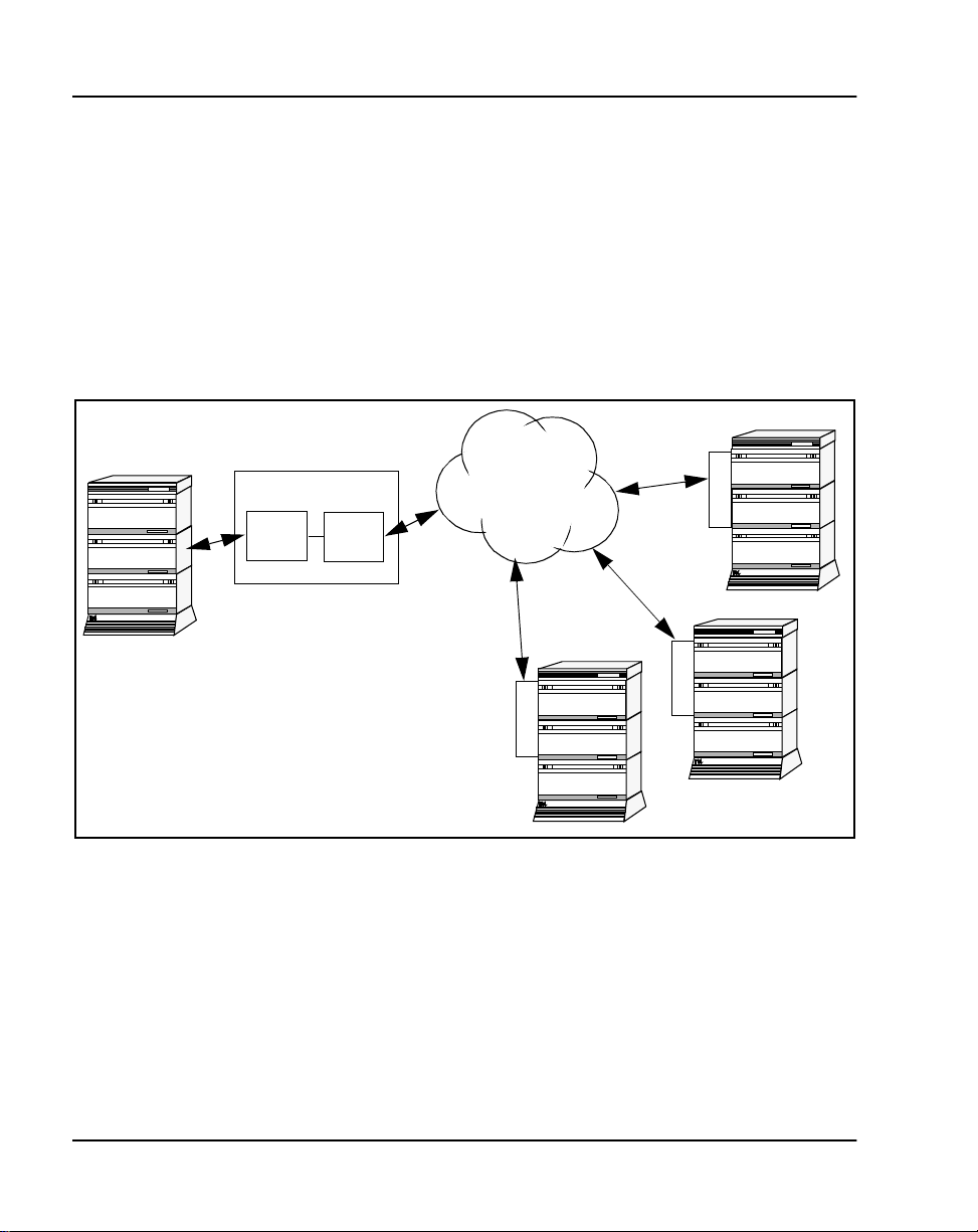
Figure 1 shows an ITG ISL Trunk configuration ex ample.
Figure 1
ITG ISL Trunk connectivity
Meridi an 1
t
DSP
DCHIP + Fol lowers
DCH
northern
telecom
ITG ISDN IP Trunk
Meridian 1 to IP network, providing
poin t t o multi-point co n n e c tio n
H.323
tandems
IP Network
I
T
G
2
Meridian 1
Meridi an 1
I
T
G
2
I
T
G
2
Meridian 1
northern
telecom
Meridian 1
northern
telecom
Meridi an 1
Meridi an 1
Note: In this document, T-LAN refers to the Telephony LAN that
transmits the ITG voi ce and fax traffic. E-LAN (embedded LAN) refers
to the management and signaling LAN for the Meridian 1 site.
ITG ISL Trunk depen ds on the manage d IP networ k, not the Internet, be cause
the managed IP network can provid e adequa te late ncy, ji tt er, and pac ket los s
performance to support VoIP with an acceptable voic e quality.
553-3001-202 Standard 1.00 April 2000
northern
telecom
553-9340
Page 21

System requirements
ITG is avai lable f or Meri dian 1 op tions 11C , 11C Min i, 51 C, 61C, 81 and 81C
systems running X11 relea se 25 or later software. See Table 1, “Software
packages for Meridian 1 ITG ISL Trunk,” on page 22 for required software
packages.
ITG requires MAT 6.6 or lat er incl uding Alarm Ma nagement. MAT Common
Services include the Meridian Internet Telephony Gateway applications.
Customers must have the NTAK02BB (minimum vintage) SDI/DCH card
(Option 11C) or MSDL card (Lar ge Sys tems) fo r ISDN Sign aling capabi lity.
If the customer does not have either of these cards, or does not have an
available DCH port on them, the cus tom er m us t order these cards to support
ISDN functionality.
A modem router must be installed on the E-LAN in order to provide remote
support access for ITG Trunk and othe r IP -ena bled Nortel Networks
products. The Nort el Net works Netg ear RM356 m odem router inte grate s the
functions of a V.90 modem, a PP P remote access server, an IP router, and a
4-port 10BaseT Ethernet hub, and provides a range of security features that
must be configured to comply with the customer's data network security
policy. The Netgear RM356 modem router can be ordered through many
electronic equipment retail outlets.
Descripti on Page 21 of
378
Customers with ITG Trunk 1.0 Basic Per Trunk Signaling 8-Port IT G trunk
cards have the option of upgrad ing t o ITG Trunk 2.0 ISDN Signali ng tr unks.
Port capacity remains 8 ports per card. 8 and 24-Port cards can be mixed in
the same ITG ISL Trunk no de. The se ction “U pgrade an IT G Trunk 1. 0 nod e
to support ISDN signaling trunks” on page 235 describes the upgrade.
ITG Trunk 2.0 ISDN Signaling Link (ISL) Description, Installation and Operation
Page 22

Page 22 of
378
Descripti on
Table 1
Software packages for Meridian 1 ITG ISL Trunk
Package Package number Notes
Basic Al ternate Route Selection
57 or 58 Required
(BARS) or Network Alternate
Route Selection (NARS)
ISDN Base (ISDN) 145 Required
ISDN Signaling Link (I S L) 147 Required
MSDL 222 (large systems) Required
QSIG Interface (QSIG) 263 (large systems) Optional
QSIG GF Transport (QSIG GF) 305 (large systems) Optional
Advanced ISDN Network
148 Optional
Services (NTWK)
Coordinated Dia ling Plan
59 Optional
(CDP).
Flexib l e N u m b ering Plan (FN P) 160 Op tional
553-3001-202 Standard 1.00 April 2000
Page 23

List of ITG ISDN components
Table 2 lists ITG ISDN components.
Note 1: MAT 6.6 or la ter, or OTM 1.0, includ ing the Common Services,
Alarm Management, and ITG ISDN appl ica tions, is a prerequisite and
must be ordered separ ately.
Note 2: Nortel Networks Netge ar RM35 6 Mod em Ro uter o r e quiv alent
is required for remote support and must be ordered separatel y from retail
outlets.
Note 3: You must ins pect the IPE modu le t o de ter mine i f it is eq uipp ed
with non-removable Molded Filter Connectors on the I/O Panel. For
Large Systems manufactured during the period of 1998-1999 and
shipped in North Americ a, the IPE modules have the NT8D81BA
Backplane to I/O Panel ribbon cable assembly with a non-removable
Molded Filter Connector. The NT8D81BA is compatible with 10BaseT
T-LAN, but if you require a 100B aseT T-L AN, you need to replace it
with the NT8D81AA Backplane to I/O Panel ribbon cable ass embly.
Table 2
Hardware components for Meridian 1 ITG ISL Trunk (Part 1 of 3)
Descripti on Page 23 of
378
Component Product codes
System Packages
ITG ISDN Signaling Trunk Large Systems P ackage
including D-Channel (NT0961AA 24-Port ITG ISL Trunk
with RTU and pre-in stalled software , I/O cables, DCH
PC card, 50-pin I/O Panel Filter connector with ITG
specific filtering for 100BaseTX, and NTP)
ITG ISDN Signaling Trunk Small Systems (Option 11C)
Pac kage including D-Channel (ITG Trunk 2.0 card with
RTU license and pre-installed software that supp orts 24
ports, required cables, DCH PC card, and NTP)
ITG ISDN Signaling Trunk Small and Large Systems
Pac kage without DCH PC Card or NTP
ITG Trunk 2.0 ISDN Signaling Link (ISL) Description, Installation and Operation
NTZC44AA
A0786079
NTZC44BA
A0786080
NTZC45AA
A0786081
Page 24

Page 24 of
Table 2
Hardware components for Meridian 1 ITG ISL Trunk (Part 2 of 3)
Upgrade Packages
378
Descripti on
Component Product codes
Upgrade Kit for Large Systems from ITG Trunk 1.0 t o 2.0
(includes required cables, DCH PC card, and NTP)
Upgrade Kit f or Small Syst ems fr om ITG Trunk 1.0 to 2.0
(includes required cables, DCH PC card, and NTP)
Spare cards
Meridian ITG Trunk 2.0 card (24 ports)
(NT0961AA 24-Port ITG ISL Trunk with RTU and
pre-insta ll ed software)
Cables
E-LAN, T-LAN, RS232 and DCH Ports cable for the
NT0961AA 24-Port ITG ISL Trunk DCHIP card.
E-LAN, T-LAN, and RS232 Po r t s cable for the
NT0961AA 24-Port ITG ISL Trunk card
E-LAN, T-LAN, RS232 and DCH Ports cable for the
NTCW80CA 8-P ort ITG ISL Trunk DCHIP card
E-LAN, T-LAN, RS232 and DCH Ports cable for the
NTCW80AA 8-P ort ITG ISL Trunk DCHIP card
DCH PC Card Pigtail cable NTCW84EA
MSDL DCH cable (included in Large System package):
6 ft.
18 ft.
35 ft.
50 ft.
NTZC47AA
A0786085
NTZC47BA
A0786086
NT0961AA
A0786146
NTCW84KA
A0784208
NTMF94EA
A0783470
NTCW84LA
A0784437
NTCW84MA
A0789752
A0744403
NTND26AA
NTND26AB
NTND26AC
NTND26AD
50 ft. MSDL DCH Extender cable NTMF04AB
A0774842
553-3001-202 Standard 1.00 April 2000
Page 25

Descripti on Page 25 of
Table 2
Hardware components for Meridian 1 ITG ISL Trunk (Part 3 of 3)
Component Product codes
10 ft. Inter cabinet cable NTCW84KA to SDI/DCH cable NTWE04AC
A0794156
1 ft. Intra cabinet cable NTCW84KA to SDI/DCH cable NTWE04AD
A0794157
378
Shielded four-port SDI/DCH cable for the NTAK02BB
SDI/DCH card (included in Small System package)
PC Maintenance cable (for faceplate RS232
maintenance port to local terminal access)
Maintenance Extender cable NTAG81BA
Large Systems filter connector
50 pin I/O Panel Filte r Connecto r Block wit h ITG speci fic
filtering for 100BaseTX (included in Lar ge Systems
package)
Backplane to I/O Panel rib bon cable assembly
compatibl e wit h NTCW84 JA I/O Panel Fil ter Connector
Block with ITG-specific filtering for 100BaseTX T-LAN
connection (r eplaces NT8D81BA Bac kplane to I/O Panel
ribbon cable assembly equipped with non-remov able
Molded Filter Connectors)
Documentation
Meridian Internet Telephony Gateway (ITG) Trunk
2.0/ISDN Signaling Link NTP
PC Cards
C7LIU DCH PC Card with Layer 2 DCH Software NTWE07AA
NTAK19FB
A0403450
NTAG81CA
A0655007
NTCW84JA
A0783483
NT8D81AA
A0359946
P0906569
A0794155
ITG Trunk 2.0 24-Po rt Software Upgrade on 8Mb ATA
Flash Rom PC Card
ITG Trunk 2.0 8-Port Software Upg rade on 8Mb ATA
Flash ROM PC Card
ITG Trunk 2.0 ISDN Signaling Link (ISL) Description, Installation and Operation
NT0963AA
A0786148
NT0962AA
A0786147
Page 26

Page 26 of
378
Descripti on
Ordering rules and guidelines
Ordering rules for ITG ISL Trunk node initial configuration
Initial confi guration of an ITG ISL Trunk node requires either :
• one NTZC44AA ITG ISDN Large Systems package, or
• one NTZC44BA ITG ISDN Small Systems package,
as appropriate for your system. These packages include all Meridian 1
components neede d for a sin gle-ca rd node, except for the cable s that provi de
interface to the MSDL and SDI/DCH cards. DCH interface cables are
included:
• NTND26AA (Large Systems)
• NTAK19FB and NTWE04AD (Small Systems)
The following packages are requi red for ITG ISL Trunk:
• ISDN Base (ISDN) package 145
• ISDN Signaling Link ( I S L) pa ckage 147
MAT 6.6 or OTM 1.1 is required and must be ordered separately. The MAT
Alarm Notification application is not included with MAT 6.6 and must be
ordered separately.
For MSDL and DCHIP cards that reside in the same Large System UEM
equipment row, order:
• NTND26 MSDL DCH cable in sufficie nt length to reach from the MSDL
to the I/O Panel of the IPE module that contains the DCHIP.
For MSDL and DCHIP cards that reside in different Large System UEM
equipment rows in a multi-row La rge System, order:
• NTMF04BA MSDL DCH Extender (50 ft.) cable to reach between the
I/O Panels of the two UEM equipmen t rows.
For SDI/DCH and DCHIP cards that reside in different Small System
cabinets, orde r:
• NTWE04AC Inter c abinet cable (NTCW84KA to SDI/DCH cabl e-10 ft.)
553-3001-202 Standard 1.00 April 2000
Page 27

Descripti on Page 27 of
If you are installing ITG ISL Trunk cards in IPE modules equipped with
NT8D81BA Backplane to I/O Panel ribbon cable assembly with Molded
Filter Connectors, and you are using 100BaseT X T-L A N, order:
• NT8D81AA Backplane to I/O Panel ribbon cable assembly compatible
with NTCW84JA Fi lter Connec tor Bl ock with IT G-spec if ic fi lt eri ng for
100BaseTX T-LAN connection.
Note: You must inspect the IPE module to determine if it is equipped
with Molded Filter Connectors on the I/O Panel. Molded Filter
Connectors were shipped in North Am erica during a period from 1998 to
1999. Molded Filter Connectors can be used with 10BaseT T-LAN
connections.
Ordering rules for ITG ISL Trunk node expansion
To expand an ITG ISL Trunk node requires:
• For each additional non-DCHIP card:
— one NTZC45AA ITG ISDN Small and Large Systems Package
without DCH PC Card or NTP.
• For each additional DCHIP ca r d , either:
— one NTZC44AA ITG ISDN Large Systems Package including
D-Channel, or
378
— one NTZC44BA ITG ISDN Small Systems (Option 11C) Package
including D-Channel,
as appropriate for your system. Make sure that there are sufficient DCH
ports on the MSDL or SDI/DCH cards and associated cables.
ITG Trunk 2.0 ISDN Signaling Link (ISL) Description, Installation and Operation
Page 28

Page 28 of
378
Descripti on
Sparing ratios for ITG Trunk components
Sparing ratios for selected components are as listed in Table 3.
Table 3
Sparing ratios
Component Sparing ratio
NT0961AA Spare Meridian Trunk ITG 2.0 card (24
ports) (for repair only -- no RTU license)
NTWE07AA C7LIU DCH PC Card with NTCW84EA
PC Card DCH Pigtail cable
I/O cable assemblies 20:1
ITG ISL Trunk card description
The ITG ISL Trunk card provides a cost-effective solution for high quality
voice and fax transmi ssions over an IP network.
The ITG ISL Trunk card is a two-slot, IPE-based assembly designed for
installation in a Meridian 1 IPE shelf. An ITG ISL Trunk card can have a
maximum of 24 ports. A Peripheral Component Interconnect (PCI)-base d
DSP daughterboard pr ovides voice processi ng and installs on the assembly.
The daughterboard compresses speech into packets and supplies the packets
to the IP network using a Pentium host processor.
The ITG ISL Trunk card monitors the IP network for delay (latency) and
packet loss . The car d rero utes n ew c alls t o t he al ternat e ci rcui t-swi tched trun k
routes if the Quality of Service (QoS) of the data network is not acceptable.
Customers can configure QoS parameters on the ITG ISL Trunk node to
make sure that the ITG Trunk route is not us ed for new calls if the network
QoS degrades be l ow an ac ce pt ab l e level.
10:1
10:1
Card roles
The ITG ISL Trunk card can have one or more of the following roles:
•Follower
• Active Leader
553-3001-202 Standard 1.00 April 2000
Page 29

Descripti on Page 29 of
378
• Backup Leader
• D-channel IP gateway (DCHIP)
The ITG ISL Trunk card roles identify which systems are active
systems/standby systems and which are client systems. The Active Leader
has a Nod e IP a ddress on the v oice interf ace. T his Node IP is an al ias I P which
is added to the original IP address on the voice interface. Other machines in
the network use the Node IP to keep track of the Active Leader.
Each Meridian 1 is usually configured with the following:
• one ITG ISL Trunk card that acts as an Active Leader
• one ITG ISL Trunk card that acts as a Backup Leader
• at least one ITG ISL Trunk ca rd that provides DCHIP functionality
• one or more ITG ISL Trunk cards identified as Followers.
In the MAT ITG application, the te rm Leader 0 refers to the ITG ISL Trunk
card initially configured to perform the role of the Active Leader. The term
Leader 1 refers to the ITG ISL Trunk card that is initially configured to
perform the role of Backup Leader. The Active Leader and Backup Leader
exchange the Node IP addres s when the Active Leader goes out-of-service.
The term A ct iv e Lea de r i n di ca t es th e Lead e r 0 or the Le ad er 1 card that is
performing the Active Leader role.
Leader 0 or Leader 1 can have the Active Leader status. On system power-up,
Leader 0 normally functions as th e Active Leader and Leader 1 as the Ba ckup
Leader. At other times, the Leader card functions reverse with Leader 1
working as the Active Leader and Leader 0 working as the Backup Leader.
The Leader, Backup Leader, Follower, and DCHIP cards communicate
through their E-LAN connections.
Follower
A Follower card is an ITG ISL Trunk card which converts telephone signals
into data packets and data packets into te lephone sign als. Followe r cards also
provide dialed number to IP address transl ation.
ITG Trunk 2.0 ISDN Signaling Link (ISL) Description, Installation and Operation
Page 30

Page 30 of
g
378
Descripti on
Active Leader
The Active Leader ca rd is an ITG ISL Trunk card that acts as a point of
contact for all other Meridian 1 in the network.
The Active Leader card is res ponsible for the following:
• distribute incoming H.323 cal ls to each registered Follower card in its
node, and balance l oad among the registered cards for inc omi ng IP calls
• IP addresses for other cards in its node
• work as a time server for all ITG ISL Trunk cards in its node
• perform network monitoring for outgoing calls in its node
• voice processing
All calls fr om a remote Meridian 1 ITG node are presented to the Active
Leade r car d. Th e L ea d er car d mai n tains a resou r ce table of al l th e ITG ISL
Trunk cards in it s node. The Act ive Leader card c onsults its internal Follower
card resource table to determine which Follower card has the most idle
channels. The Active Leader card selects this card to receive the new call. The
Active Leader sends a message to the se lected Follower card, informing it to
reserve a channe l for the ne w call. I t redire cts the ca ll to the sele cted Fol lower.
The Follower card performs dialed number to IP address translation.
Backup Leader
The Backup Leader card steps in when the Leader is out-of-service. This
minimizes service interruptions.
D-channel IP
The ITG ISL Trunk card with DCHIP functionality (DCHIP Card) is
connected by the RS-422 cable to the Multi-purpose Serial Data Link
(MSDL) card on the Meridian 1 large systems. It connects to the SDI/DCH
Card on small systems. The DCHIP Card is equipped with a DCH PC Card.
The DCH PC Card provides the RS-422 and LAPD functionality that is
required for the D-channel (DCH) inter f ac e to the Meridian 1. The DCHIP
Card is the network side of the Meridian 1 ISL D-channel connection. The
card is a ta ndem node in the s witch net work, prov iding a s ingle-to mul ti-poin t
interface betwe en the Meridian 1 and the IP network (see Figure 2).
553-3001-202 Standard 1.00 April 2000
ateway (DC HIP)
Page 31

Figure 2
ITG architect u re
Descripti on Page 31 of
Core Switch
378
Core Switch
DCHIP + Followers
DCH H.323
The ISL connection to the Meridian 1 fun ctions as it does in a normal ISDN
network. The IS L controls the call pr ocessing fo r calls ove r analog ITG IDSN
Signaling Link (IS L) T I E trunks. These ISL TIE trunks can be on a ny of the
ITG ISL Trunk cards. The ITG ISL D-chann el only controls ITG ISL Trunk
cards in the same ITG nod e. MAT a dministration rel ates the c ards with trunks
to the DCHIP ITG Trunk card.
IP Network
ITG
Core Switch
ITG
Core Switch
ITG
553-9481
The ITG ISL Trunk card uses ISDN messages for call control and
communicates with the Meridian 1 through the PC Card, using the RS-422
link. On the Meridian1, the MSDL pro vides the ISL DCH inter f ace. The
DCHIP ITG Trunk card software performs the tandemin g of DCH call control
to the H.323 protocol.
ITG Trunk 2.0 ISDN Signaling Link (ISL) Description, Installation and Operation
Page 32

Page 32 of
378
Descripti on
Each DCHIP ITG Trunk card can be associated with up to 382 trunks. The
trunks reside on 24-po rt ITG ISL Trunk cards. This creates a functional
grouping of trunk cards with the DCHIP ITG Trunk card provi din g the DCH
connectivity. If more than 382 trunks are required, additional DCHIP ITG
Trunk card groups are config ured, each with a maximum of 382 rela ted
trunks. (See Figure 3).
Figure 3
Leader, DCHIP, and trunks in an ITG node
ITG NODE
Active
Leader
Backup
Leader
DCHIP + Follower Trunk "group"
DCHIP
DCHIP + Follower Trunk "group"
DCHIP
DCHIP + Follower Trunk "group"
DCHIP
Follower
Follower
Follower
553-9482
553-3001-202 Standard 1.00 April 2000
Page 33

Card combinations
The Leader and DCHIP, or Follower and DCHIP, functions can reside on a
single card or multiple card s. If a Follow er card is equipped with a DCH PC
card, it can function as a DCHIP ITG Trunk card. As a ITG Trunk node
becomes larger with more t runk t raffic , l oad ba lanci ng shoul d be co nfigu red.
When load balanc ing is required, the Leader and DCHIP functionality are
placed on separate cards which are assigned the least call traffic. For the
largest ITG Trunk nodes and netw orks , the Leader and DCHIP cards can be
partially c onfigured with trunk ports or have no trunk ports at all.
An example configura tion that allows for redundancy and bac kup is the
following:
• Card 1: Leader and DCHIP #1
• Card 2: Backup Leader and DCHIP #2
• Card 3: Follower #1 – 24 trunks connected with DCHIP #1
• Card 4: Follower #2 – 24 trunks connected with DCHIP #2
To support more trunks, more DCHs can be added. Each DCHIP card can
support a maximum of 15 NT0961AA 24-Port Follower cards. This limit is
due to the maximum limit of 382 trunks in an ISL route.
Descripti on Page 33 of
378
Note: Each DCHIP control s a separate group of Follower cards. If a
DCHIP fa ils, its ass oci at ed F oll ower s ar e r emov ed from ser vic e as w ell .
For very large nodes, it is recommended that Foll ower cards be spread
across multipl e DCHIPs, in or der to prov ide some resil iency by allo wing
the ITG node to continue handling calls if one DCHIP fails.
A DCHIP card and all of the ITG ISL Trunk cards connected with it belong
to one Leader car d . This mea n s that the cards also belong to a single
customer. The group of ITG ISL Trunk cards connecte d with one Leader is
referred to as an ITG Node. If a single Meridian 1 system has multiple
customers req uiring IP trunk conne ctivity, a separate ITG node is required f or
each customer. Multiple DCHIPs can be configured f o r each node.
Note: All DCHIPs in an ITG node must be configured with the same
DCH protocol. If t he u ser wants to use multi ple DCH prot oc ols, the user
must configure mu ltiple ITG nodes.
ITG Trunk 2.0 ISDN Signaling Link (ISL) Description, Installation and Operation
Page 34

Page 34 of
378
Descripti on
Each customer require s one or more dedica ted ITG nodes . ITG trunks on the
same ITG node share the same di aling plan a nd IP network connec tivity. ITG
trunks cannot be s hared bet ween customers that have in dependent numbering
plans and IP networks.
It is possible to configure multiple ITG nodes for one customer. This
configuration allows load balancing among multiple Leaders for sy st em s
with more traff ic than a singl e Leader c ard can supp ort. The configur at ion of
multiple ITG nodes on on e custome r requires splitt ing the di aling pla n among
the Lead er s. Eac h Le ade r mus t ha ve a di stin ct r an ge of the dia lin g plan . Th i s
restriction exists so that a remote gateway can relate a DN with a single IP
address.
Note: For information about engineering an ITG node, plea se refer to
the Engineering Guideli nes section.
Interactions among card functions
Active Leader and Foll ow er card interaction
The Active Leader card controls the assignment of IP addresses for all new
ITG ISL Trunk cards in its node. If a new ITG ISL Trunk card is added as a
Follower, the new Ca rd Configuration data, as programmed in MAT, is
downloaded only to the Active Leader card. When it boots up, the new
Follower card reque sts its IP a ddress from the Activ e Leader car d through the
protocol. When the Follower cards boot up, they recei ve their IP
ERRWS
address and Active Leader ca rd IP address from the Active Leader card.
Follower cards continuously send Update messages to the Active Leader
card. These mess a g es in f o r m th e A ctive Leader car d of th e F o ll o w er s’ m o st
recent stat us and re sources . The Act ive L eader se nds Upd ate mess ages t o the
Follower cards , informing them of the up dated dialing number to IP address
translation information. Also the Active Leader card continuously s ends
messages about changes in the netw ork performanc e of each des tinatio n node
in the dialing plan.
If a Follower card fails (for example, DSP failure), it reports to the Active
Leader that its fai led resour ces are not availa ble. The trunk por ts involved are
considere d f aulty and appear busy to the Meridian 1. Call processing is
maintained on the remaining ITG trunks.
553-3001-202 Standard 1.00 April 2000
Page 35

Descripti on Page 35 of
378
If a Follower card loses communication with the Active Leader, all its ports
appear busy to the Meridian 1. Alarms are raised by sending an Simple
Network Manag ement Pro tocol (SNMP ) trap t o the IP address es in the SN MP
manager list.
Active Leader and Backup Leader interaction
When a Lea d er ca rd r eb o ot s in t o se rv i ce , it se n d s
whether an Active Leader card is present. If it receives a
requests to check
ERRWS
ERRWS
response, t his
indicates the presence of an Active Leader card and the rebooting Leader
becomes the Backup Leader. If it does not receive a
ERRWS
response, this
indicates the absence of an Active Le ader and the reboot ing Leader becomes
the Ac ti v e Le a d er .
The Backup Leade r moni tors the heartbeat of the Active Leader by pinging
the Acti ve L ea der ’s Node IP . In th e e vent of th e A ctiv e L ea der’ s fa il ure (th at
is, the Active Leader is not responding to the pinging of the Node IP address
by the Backup Leader ), the Backup Lea der takes over the Active Leader role ,
in order to avoid service interruption. The Bac kup Le ader assigns the Node
IP to its voi ce inte rface and anno unces it s new status to all the Fol lower card s.
The Fo llowers re- register with the new Active Leader and , as a result, a new
Resource Ta ble is built immedia tely.
The Leader 0 and Leader 1 cards keep their node properties sy nchronized.
The Backup L eader receive s a copy of the
.1 file, containi ng the
ERRWS
ERRWS
table, from the Active Leader on bootup and when Node Properties are
downloaded to the Active Leader.
ITG Trunk 2.0 ISDN Signaling Link (ISL) Description, Installation and Operation
Page 36

Page 36 of
378
Descripti on
Critical synchronized data includes:
• the card index:
– index 1 indicates Leader 0
– index 2 indicates Leader 1
– index 3 or greater indicates Follower
• the Management MAC address (mot herboard Ethernet ad dres s),
• the Node IP address,
• the individual card IP addresses and card TNs for all ITG ISL Trunk
cards in the ITG node.
• D-Channel number, card density and First CHID.
In the event of a Backup Le ade r failure, the Leader card generates an SNMP
trap to the MAT management station, ind icating this failure.
If the Active Le ader and Backup Leade r are reset, removed, or disconnected
from the LAN at the same time, the entire I TG node is put out-of-service. If
this situation occurs, manual intervention is required to recover the system.
Active Leader/Backup Leader and DCHIP card interaction
The Activ e Leader checks the status of t h e DCHIP card . The DCHIP card
must constantly info rm the Le ade r of its DCH status and its ca rd status .
When a DCH I P I TG Tr u nk ca r d f ai lu re occurs , the associ at ed tru n ks ’ st at es
appear busy to the Meridian 1, so the trunks will not be us ed for calls. This
blocks the normal software action of reverting to analo g si gnaling when an
ISL DCH fails. If either end’s DCHIP or DCH connection fails, ISDN
protocol f eatures acros s the IP network do n ot fun ction. When a DCHIP ca rd
fails, its associ at ed Fo ll o w er s are also re mo v e d fro m s e rvice.
In the case of a DCH failure, established calls are maintained; however, no
new calls can be made. Calls in a transient state are dropped.
553-3001-202 Standard 1.00 April 2000
Page 37

ITG ISL Trunk card physical description
The Meridian 24-Port ITG Trunk 2.0 card (NT0961AA) plugs into an
Intelligent Peripheral Equipment (IPE) shelf. Each ITG ISL Trunk card
occupies two slots. ITG ISL Trunk cards have a E-LAN management
Ethernet port (10B aseT) and a T-LAN VoIP Ethe rnet port (10/ 100Bas eT) on
the I/O panel. The ITG ISL Trunk card has a DIN-8 serial mai ntenance port
connection on th e faceplate and an alternative connection to the same seria l
port on t he I/O backpla ne . Do not c onnect two mainten ance termi nals to bot h
the faceplate and I/O panel serial maintenance port connections at the sam e
time.
The NT0961AA ITG ISL Trunk card supports 24 ports per card.
The core ITG processor is an Intel Pentium II (266 Mhz).
The ITG ISL Trunk card is responsible for converting the 64 kbit/s Pulse
Code Modulation (PCM) speech from the DS-30X backplane interface into
packetized s pee ch for transmission over the IP network. On the
daughterboard, the DSPs compress speech and feed the resulting packets to
the IP networ k.
Figure 4 on page 38 shows ITG ISL Trunk card system connectivity.
Descripti on Page 37 of
378
ITG Trunk 2.0 ISDN Signaling Link (ISL) Description, Installation and Operation
Page 38

Page 38 of
378
Descripti on
Figure 4
ITG system connectivity and messaging
IPE Shelf
SSD Trunk
Signaling Messages
Meridian 1
MSDL
XNET
XNET
Intercard ISDN Call
Control Messages
XPEC
(ISL DCH)
RS-422
MAT PC
10BaseT (Mgmt/Signaling)
DCHIP
DSP D/B
PCMCIA
DS-30X
ITG
DSP D/B
10/100BaseT
(Voice/fax)
IP Network
H.323 Call
Control Messages
553-9462
553-3001-202 Standard 1.00 April 2000
Page 39

Faceplate indicators, controls, and interfaces
The ITG ISL Trunk card has a double width faceplate using the shortened
lock latches as shown in F igure 5.
Figure 5
ITG ISL Trunk card (NT0961AA)
NWK
Descripti on Page 39 of
Ethernet Voice Port
378
Card Status LED
Reset Switch
RS-232
Maintenance Port
ITG
Reset
NWK
Status
A:
NT0966AA
Maint
Port
Ethernet LEDs
Type III PCMCIA slot
(ATA Drive A:)
Four-character LED-based
Matrix Maintenance Display
Inboard:
- Type III PCMCIA slot (ATA Drive B:)
- Onboard Flash Drive C:
553-9150
ITG Trunk 2.0 ISDN Signaling Link (ISL) Description, Installation and Operation
Page 40

Page 40 of
378
Descripti on
Card Status LED
A single red, card sta tus LED on the facepla te indicat es the ena bled/disabl ed
status of th e 24 port s on t he ca rd. The LED is on (red) d uring the powe r up or
reset se quence. The LED remains lit until th e card correctly bo ots and
assumes its role (that is, Leader, Backup Leader, Follower or DCHIP). If the
LED remains on, one of the following has occurr ed:
• that self-test has failed (the Faceplate Maintenance Display indicates the
cause F:xx)
• the card has rebooted
• the card is acti ve, but there are no trunks confi gured on it (for example,
the car d is a Leader o r DCHIP)
• the card is active and has trunks, but the tr unks are disabled (that is, the
trunks must be ena bled in LD 32)
Note: During configuration, the error message “F:10” can appear. This
error indicates a missing Security Device. It occurs since Security
Devices are not implemented on ITG Trunk 2.0. You can igno re this
message.
See “ITG Trunk 2.0 faceplate maintenance displa y codes” on page 329 for a
comple te list of fac eplate cod es.
Ethernet status LEDs
Ethernet status LEDs for the voice inte rface on the daughte rboard dis play the
Ethernet activity as follows:
• Green is always on i f t he carrier (l ink pul se) i s rece ived fro m the T-LAN
Ethernet hub.
• Yellow flashes when there is data activity on the T-LAN.
• During heavy traffic, yellow can stay conti nuously lit.
Note: There are no Ethernet status LEDs for the management interface
on the motherboard.
553-3001-202 Standard 1.00 April 2000
Page 41

Descripti on Page 41 of
y
378
Reset switch
A reset switch o n the fac ep late allows an operator to manually reset the card
without having to cycle power to the card. This switch is normally used
following a software upgrade to the card or, alternatively, to clear a f ault
condition.
PC Card socket
There ar e t wo PC Ca rd so cke ts . The fa ce pla te socket acc ept s eit her a T yp e I,
II, or Type II I PC Card and i s desi gnated ATA devi ce A: . The i nterna l soc ket
is reserved for the NTWE07AA C7LIU DCH PC Card on the DCHIP.
Maintenance displa
This is a four c haracter, LED-ba sed dot matri x display . It shows the card b oot
sequence and is labeled with the card role as follows:
• LDR = Active Leader
• BLDR = Backup Leader
• FLR = Follower
RS-232 maintenance port
The ITG ISL Trunk ca rd has a DIN-8 serial mai ntenance port connection on
the faceplate and an alternative connection to the same serial port on the I/O
backplane. Do not connect two maintenanc e terminals to both the fa ceplate
and I/O panel serial maintenance port connections at the same time.
Voice Ethernet port (T-LAN)
The faceplate Eth ernet conn ector i s a 9-pin , sub- minia ture D-t ype connector.
The voice Ethernet port on the daughterboard is i dentified as “lnPci 1” in the
ITG shell.
WARNING
Do not connect a T-LAN cable to the Facepl ate 9-pin Voice port
connector (NWK). You must connect the T-LAN cable to the I/O
cable.
ITG Trunk 2.0 ISDN Signaling Link (ISL) Description, Installation and Operation
Page 42

Page 42 of
g
g
378
Descripti on
Backplane interf aces
The following interfa ces are provided on the ITG backplane conne ctor:
DS-30X voice/si
Carries PCM voice and proprietary signaling on the IPE backplane between
the ITG Trunk card and the Intelligent Peripheral Equipment Controller
(XPEC).
Card LAN
Carries card polling and initialization messages on the IPE backplane
between the ITG Trunk card and the Intelligent Peripheral Equipment
Controller (XPEC).
RS-232 serial mainten ance port
An alternative connec tion to the serial ma intenance port exists on the I /O
backplane. Us e the NTCW84KA or NT MF94EA I/O pane l b reakout cabl e to
access the port. A DIN-8 serial maintenance port connection exists on the
faceplate. Do not connect two maintenance terminals to both the faceplate
and I/O panel seria l maintenance port connect ions at the same time.
Assembly description
The ITG ISL Trunk card assembly consists of a two-slot
motherboard/da ughterboard combina tion, as shown in F igure 6 on page 43. A
PCI interconnec t board connects the ITG motherbo ard and the DSP
daughterboard.
The ITG ISL Trunk card is not user-s erviceable. Figure 6 on page 43 is
for information purpos es only. Do not remove the daughterboard from
the motherboard.
nalin
CAUTION
553-3001-202 Standard 1.00 April 2000
Page 43

Figure 6
Mechanical assembl y
Descripti on Page 43 of
PCI Connectors
378
Two-Slot Faceplate
ITG
PCI
Board
Motherboard
Daughterboard
G200402
ITG Trunk 2.0 ISDN Signaling Link (ISL) Description, Installation and Operation
Page 44

Page 44 of
378
Descripti on
ISDN Signaling Link
ISDN Signalin g Link (ISL ) pro vides t he capab ility of r epl acing conven tio nal
analog trunk signaling with out-of-band IS DN D-channel signaling.
The ISL interface makes available the flexibility of using ISDN signaling to
analog facilit ies. When no PRI exists between two Meridian 1 systems, ISL
operates in dedicated mode. A dedicated point-to-point signaling link is
established between the two Meridian 1 systems. The signaling information
for the s elected a nalog tru nks is transpo rted over the IS DN signaling link. The
analog ISL TIE trunks are for user voice transport. If the D-channel link is
down, call control returns to normal in-band analog trunk signaling.
The ITG is similar to the existing ISL con figurat io n w h ere there is a VPN
between Meridian 1 s ystems. Instead of a one-to-one connection, multiple
switches can be networked through a single ISL interface at each site.
Figure 7 on page 45 shows an ITG ISL Trunk configuration with three
Meridian 1 systems. ITG ISL Trunk simulates an analog facility. The ISL
interface is conne cte d to a DCHIP PC Card which provides ISDN to VoIP
tandeming. All ITG ISL Trunk cards (DCHIP, Leader, and Follower) are
connected through the Embedded Local Area Network (E-LAN). ITG ISL
Trunk cards communic ate with remote switches through the IP network.
553-3001-202 Standard 1.00 April 2000
Page 45

Figure 7
ITG configuration
Descripti on Page 45 of
MSDL
ISL
DCHIP
Leader
378
Follower
MSDL
DCHIP
Leader
Follower
LAN
ISL
LAN
553-9472
LAN
ISL
MSDL
DCHIP
Leader
Follower
Router
IP Network
Router
Router
ISDN signaling between the Meridian 1 and the ITG ISL Trunk supports the
delivery of Calling Line Identification (CLID) and feature messaging. ISL
DCH signali ng provide s th e n ecess ary s ignali ng conne ction ove r which dat a,
including CLID and feature-specific messaging, can be passed.
ITG Trunk 2.0 ISDN Signaling Link (ISL) Description, Installation and Operation
Page 46

Page 46 of
378
Descripti on
On large systems, the DCH interface to the Meridian 1 uses the MCDN or
QSIG GF protocols and their variants to transmit call and feature control
messages to the DCHIP card. Small systems use only MCDN because the
NTAK02BB SDI/DCH card does not support QSIG protocols for ISL. The
DCH interface uses thes e protocols and their variants, as they have the
following advantages:
• ISL configuration support
• symmetry (incomi ng and outgoing call messagi ng is the same)
• near H.323 standard
QSIG GF Name Display is the only supp orted QSIG supplementary service.
The ITG feature compli es with H.323 Basic Call Q.931 signalin g. T his part
of the H.323 standard (H.225) defines the messa ging used to setup and rele ase
basic calls. A mechanism is implemented to enable the passing of ISDN
messaging thro ugh t he IP network be tween t he two end points . Th e cal l is set
up using the H.323 standard signaling with encapsulated ISDN-specific
information . Thi s mechanism allows interworkings with other gateways .
The DCHIP card provides the tandem between the ISDN signaling and the
H.323 protocol. If the DCHIP functionality is combined with the Follower
card, messages are sent between the DCH Processor and the H.323 Processor.
Most configur ations s plit this functio nality between t he DCHIP and Fol lower
cards. Figure 8 shows the signal flow from the DCH to the H.323 stack.
553-3001-202 Standard 1.00 April 2000
Page 47

Figure 8
Signal flow from the DCH to the H.323 stack
Descripti on Page 47 of
378
Backplane
FOLLOWER
H.323
Processor
VxWorks
TCP/IP
H.323
Signaling/Voice
553-9475
Meridian 1
MSDL
DCH
Processor
DCH
10BaseT Ethernet
10/100BaseT Ethernet
DCHIP
VxWorks
TCP/IP
Intercard Signaling
(E-LAN)
(T-LAN)
Note: For further informati on on I SDN Signaling Link (ISL), refer to
X11 System Management Ap plications (553-3001-3 01), ISDN PRI:
Installation (553-2901-201), and ISDN PRI: Maintenance
(553-2901-501).
Inter-card signaling paths
The Leader, DCHIP, a nd Fol lower c ards commu nicat e using th ei r E-LAN IP
addresses. Figure 9 illustrates the Meridian 1 IP signaling paths us ed
inter-card, and between the cards and the Meridian 1 system, in the ITG
offering.
ITG Trunk 2.0 ISDN Signaling Link (ISL) Description, Installation and Operation
Page 48

Page 48 of
378
Descripti on
Figure 9
ITG ISL Trunk card signaling paths
Meridian 1
DS-30X
ISL DCH
DS-30X
DS-30X
DS-30X
Leader
PRI
DCHIP
PRI
Follower
PRI
Follower
PRI
KEY
Leader/Follower
IP Messages
DCHIP/Follower
IP Messages
Timeslot port
connection (SSD)
ISL DCH
connection
553-9476
In Figure 9, the DS-30X connection is part of the Meridian 1 IPE shelf’s
backpl ane. The I SL DCH connection is a cable th at runs fr o m the “octopus”
breakout ca ble, on the ba ck of t he IPE ca binet, t o one o f t he MSDL’s RS-42 2
ports. The Leader/ Follower card messages normally travel over the T-LAN.
The DCHIP messages tra vel over the E - LAN: a 10BaseT LAN connected to
each ITG ISL Trunk card and the MAT PC. A separate 10/100BaseT LAN
transmits the voice/fax data to the remote VoIP systems.
553-3001-202 Standard 1.00 April 2000
Page 49

Dialing plans
Descripti on Page 49 of
Dialing plan configuration allows customers to s et up routing table s t o route
calls to the appropriat e destinati on, based on dialed digits. The dialing pla n is
configured through the Electronic Switched Network (ESN) feature, using
overlays in the Meri dian 1 or MAT. With ESN con figu ration, the Mer idi an 1
can route outgoi ng ca lls to the ITG ISL Trunk card. Address translation
allows the ITG ISL Trunk card call proce ssing to translate the called party
number to the IP address of t he terminating ITG node, and to deliver calls to
the destination through the IP network.
The Meridian 1 ITG ISL Trunk card supports the following dialing plans:
• North American dialing plan
• Flexib l e N u mb er i n g Pl an
Customer-defined Bas ic Automatic Route Selection (BARS) and Network
Alter n ate Route Selection (NARS) Access Codes are used to access the
dialing plans.
The ITG Trunk dialing plan supports a single Meridian 1 customer per ITG
node and multiple ITG nod es per Merid ian 1. A cu stomer may ha ve multipl e
nodes in a Meridian 1, but each node can only support the dial ing plan of a
single customer. Multiple Meridi an 1 customers will require multiple nodes
per Meridian 1.
378
Multi-node configuration
The following example explains a possible configuration between two
Meridian 1 switches to achieve both resiliency into the IP network and load
balancing.
Meridian 1 swi tch A ha s t wo ITG node s, A1 and A2, fo r the desti natio n NPA
613. A Route Li st Block (RLB) is created, in order to have two route entries
(one for each ITG node). If the trun ks of node A1 are all in us e or node A1 is
down, call t raffic is rou ted to node A2. This provides r esiliency by preventi ng
failure of a single IT G node (for e xample, DCH fail ure or Leade r subnet f ails)
from completely eliminating VoIP service for a Meridian 1 system.
It is desirable to distribute calls to multiple nodes at a remote destination
Meridian 1. The conf iguration of multi ple dial ing plan e ntries at the local ITG
node allows routing based on the dialed digit s.
ITG Trunk 2.0 ISDN Signaling Link (ISL) Description, Installation and Operation
Page 50

Page 50 of
378
Descripti on
For example, Meridian 1 switch B node B1 has two entries for NPA 408 and
4085 which point to nodes A1 and A2 of Meridian 1 switch A, respectively.
Calls from B1 with dialed digi ts 408- 5xx-xxxx are rout ed to the ITG node A1
while all other 408-xxx-xxxx calls are routed to ITG node A2.
North American dialing plan
The North American dialing plan is used to make publi c net w ork ca lls
through the private IP network. However, calls are not directly routed to the
Central Office (CO) through the LAN connection. Instead, a tandem switch
with voice tru nk connec tions , incl udi ng T1 ISDN PRI, s erves as the ga teway
to route voice calls coming through the LAN to the voice trunk.
Figure 10 shows DN 7000 placing a public call, th rough the private LAN, by
dialing 1-415-456-1234 or 566-1234. The ITG ISL Trunk card with IP
address 47.82.32. 124 searche s for the Numbering Pla n Area (NPA) or Local
Exchange Code (NXX) tables with th e matched NPA or NXX entries. When
an entry is found, the c orres ponding IP address is used to send H.323 call
setup messages to the gateway (a Meridian 1 with an IP address of
47.82.32.123), which routes the call to the PSTN through a regular CO or
DID trunk.
The translation table is expanded to allow extended, three-to six-digit NPA
codes. For e xample , DNs, such as 1-415- 456-XXXX and 1-415 -940-XXXX,
can have different des tination IP addresses.
553-3001-202 Standard 1.00 April 2000
Page 51

Figure 10
North American dialing plan — call flow
Descripti on Page 51 of
378
Rls
HOLD
DEF
ABC
3
21
MNO
JKL
GHI
6
5
4
WXY
TUV
PRS
9
8
7
0
DN 7000
CPE
Translation Table
NPA
IP Address
415
47.82.32.123
NXX
566
Flexible Numberi ng Pla n
A Flexible Numbering P lan (FNP) allows the length of Location Codes
(LOCs) to vary from node to node. As well, the total number of digits dia led
to reach a stati on can vary from stati on t o sta tion. It al so al lows flexibi li ty for
the length of the lo cation codes from node to node. An FNP can be used to
support count ry-specific dialin g plans. FNP also allows us ers to dial num bers
of varying lengths to terminate at a destination. Flexibility of the number of
digits which can be dialed is achieved using Spec ial Numbers (SPNs).
Meridian 1 Meridian 1
ITG
47.82.32.124
ITG
47.82.32.123
WAN
Outgoing call path
COT/
DID
553-9474
Electronic Switched Network (ESN) Network Signaling
ITG Trunk 2.0 supports ESN5 Network Signaling protocol only, in addition
to standard (i.e., non-network) signaling. ITG 2.0 supports a mixed network
consisting of ESN5 an d standard network signaling nodes.
ITG Trunk 2.0 ISDN Signaling Link (ISL) Description, Installation and Operation
Page 52

Page 52 of
378
Descripti on
Echo cancellation
All telephony voice service s now in use reflect some level of echo bac k to the
user. The term “echo” refers to the return of a signal’s reflection to the
originator.
Packet voice networks introduce sufficient latency to cause what a caller
would consider an audible echo. The echo path is round-trip. Any speech
coding, packetization, and buffering delays accumula te in both directions of
transmiss ion, increasin g the likelihood of audibility.
Silence Suppression
The purpose of Silence Suppression is to reduce bandwidth consumption.
With the H.225 protocol, coders can send silence frames before the end of
transmission, during a period of silenc e. Coders may omit sending audio
signals during periods of silence after sending a single frame of sile nce, or
send silence background fill frames, if these techniques are specified by the
audio codec in use.
For applications that send no packets during silence, the first pa cket after a
silence period is distinguished by setting a marker bit in the Real Time
Protocol (RTP) da ta header. Applicat ions without Silenc e Suppression set the
bit to zero.
DTMF Thro ugh Dial
Preservation and transport of tones through the IP network is critic al for
Interactive Voice Response ( I V R) services. The ITG makes sure that DTMF
tone information is included in the packets that are sent through the IP
network, and that the tones are retransmit ted by the far-end gateway. The
duration inform ation for DTMF signals is not tr ansmitted, i.e., long DTMF
bursts are reduced to a short standard duration.
Callers c an acces s tr adi tional Voice Ma il or IVR se rvices, inc luding “ Press 1
for more information” or “Pre ss 2 to be connected to our customer servic e
department”. S ervices that de pend on long DTMF b urs ts cannot be acc es s ed.
553-3001-202 Standard 1.00 April 2000
Page 53

Quality of Service
Quality of Service (QoS) is t he gau ge of qua lity of the IP network between
two nodes. As QoS d egrade s, e xist ing ca lls suff er p oor vo ice a nd fax qua li ty.
New calls will not be ini tiated if transmissions degrade below an acceptable
level.
Behavioral c haracteristics of the IP network depend on:
• Round Trip Time (RTT)
•latency
• queuing delay in the intermediate nodes
• packet loss
• available bandwidth.
The Type of Service (TOS) bits in the IP packet header can affect how
efficiently data is routed through the network. For further information on
ToS, see “Type of Service” on page 59.
Packet jitter relat ed to latency affe cts the quality of rea l- time IP
transmissions. For good voice quality, the ITG ISL Trunk card reassembles
the voice packe ts in a n ordere d contin uous s peech st ream and pl ays th em out
at regular intervals despite varying packet arrival times.
Descripti on Page 53 of
378
The user configure s a required QoS for the ITG node i n MAT. The QoS valu e
determine s when c alls Fa llback to alte rnate faci lities due to po or per forman ce
of the data network. The QoS value is between 0.0 and 5.0, where 0.0 means
never Fallback to alternate facilities, and 5 means Fallback to alternate
facilitie s unless the voice qua lity is per fect. When the QoS for outgoing calls,
as measured by the Leader card, falls below the configured value, calls
Fallback to alternate fac ilitie s. Once the QoS rises abov e th e configur ed
value, all new outgoing calls are routed th rough the IP network.
Note: QoS is measured per remote gateway. For example, if a given
Leader has three remote leaders in its dialing plan table, it will perform
three QoS measurements and calculations (one per remote gateway).
ITG Trunk 2.0 ISDN Signaling Link (ISL) Description, Installation and Operation
Page 54

Page 54 of
y
y
y
378
Descripti on
Since IP trunks use the same port for both voice and fax, the s ame QoS
thresholds apply for both voice and fax calls. Network requirements for fax
are more stringent tha n for voice. Fax protocols, such as T.30 , are more
sensiti ve to transmiss ion errors than the human ear.
Quality of Service parameters
Quality of Service for both voice and fax depends on end-to-end network
performance and availabl e bandwidth. A number of parameters determi ne the
ITG voice QoS over the data ne twork.
Packet loss
Packet loss is the percentage of packets sent that do not arrive at their
destinat ion. Packet loss is caus ed by transmission equipment problems and
congestion. P acket loss c an also occur when pa cket dela ys exceed configu red
limits and the packe ts are discarded. In a voice conv ersation, packet loss is
heard as gaps in the conversation. Some packet loss, less than five percent,
can be acceptable without too much degradation in voice quality. Sporadic
loss of small packets can be more acceptabl e than infrequent loss of large
packets.
Packet dela
Packet delay is the time bet ween when a pa cket is s ent and whe n it is rece ived.
The total packet delay time consists of fixed a nd variable delay. Variable
delay is more manageable than fixed delay, as fixed delay is dependent on
network technology. Variable delay is caused by the network routing of
packets. The ITG node must be as close as possible to the network backbone
(WAN) with a minimum number of hops, in order to minimize packet delay
and increase voic e quality. ITG pr ovides echo ca ncellatio n, so that a one -way
delay up to 200 mil li seconds is a cceptab le . For mo re inform atio n ab out Echo
Cancella tion, see “Echo cancellation” on page 52.
Dela
variation (jitter)
The amount of variation in packet delay is referred to as delay variation or
jitter. J itter affects the abi lity of the receiving ITG ISL Trunk card t o assemble
voice packets into a continuous stream when th e packets are received at
irregular intervals.
Latenc
Latency is the amount of time it takes for a discrete ev ent to occur.
553-3001-202 Standard 1.00 April 2000
Page 55

Bandwidth
Bandwidth is a measure of info rmation carrying capacity available for a
transmission medium. The greater the bandwidth the more information that
can be sent in a given amou nt of time. Bandwidth is expre ssed in bits per
second (bps).
Network performance utilities
Two common network performance utilities, PING and Traceroute, are
described be low. Other utilities can be us ed to gather i nformation about ITG
network performance.
Note: These descriptions are for reference purposes only. Traceroute is
not part of the ITG product.
Because network conditions can vary over time, collect performance data
over a period of at least four hours. Use performance utilities to measure
network performance from each ITG node to every other ITG node in your
network.
Packet InterNet Groper (PING)
Packet InterNet Groper (PING) send s a n Internet Control Message Protoc ol
(ICMP) echo request messa ge to a host, exp ectin g an ICMP echo reply . This
allows the measurement of the round-trip time to a selected host. By sending
repeated ICMP echo reques t mes sages, the percentage of packet los s for a
route can be measured.
Descripti on Page 55 of
378
Traceroute
Traceroute uses the IP Time-to-Live (TTL) field to forward route r hops to a
specific IP address. A router mu st not forward an IP packet with a TTL field
of 0 or 1. It must, instead, discard the packet and return an ICMP “time
exceeded” message to the originating IP address. Traceroute uses this
mechanism by sending an IP datagram with a TTL of 1 to the specified
destination host. The first router to handle the datagram returns a “time
exceeded” message. This identifies the firs t router on the route. Tracerout e
sends out a datagr am with a T TL of 2. Thi s caus es the second router on the
route to r eturn a “tim e exceeded” m essage, and so on, unti l all hops ha ve been
identified . The trac eroute IP data gram has a Port num ber unli kely to be in use
at the destination (usually >30,000 ) . This causes the destination to r eturn a
ITG Trunk 2.0 ISDN Signaling Link (ISL) Description, Installation and Operation
Page 56

Page 56 of
y
378
Descripti on
E-Model
“port unreachable” ICMP packet which identifies the destination host.
Traceroute can be us ed to measure round-trip times to all hops along a route,
identifying bottlenecks in the network.
The ITG uses the E-Model, a m ethod similar to the ITU-T Recommendation
G.107, to determine voice quality. This model evaluates the end-to-end
network transmis sion performance and outputs a scalar rating, R, for th e
network trans mission quali ty. The ITG us es a simplif ied versi on of the model
to correlate the network QoS to the subjective Mean Opinion Score (MOS).
MOS is a numerical scale used to rate voice quality. When MOS is equal to
5.0, voice qua lity is good. When MOS is equal to 0.0, voice quality is bad.
For packet loss over 16%, the MOS value is set to 0, and the remote node is
considered to be in fallback mode.
End-to-end latenc
IP network end-to-en d latency co nsists of several components : routi ng delay
on the I P network, fr ame duratio n dela y and J i tter Buffe r dela y on c odec, and
delay on t he circu it-switc hed network. T he determina tion of end-to-end delay
depends on the dynamics of the IP network and the detailed service
specification.
MOS values are ca lculate d based on the rou ting delay and frame durat ion and
Jitter Buffer delay on the codec. These late ncies must be taken into
consideration during the engineering of the total network’ s latency. If the
end-to-end lat enc y of the network is specifie d and the latency of the PSTN
circuit-switched components is removed, t he remainder is the latency
available f or the IP trunks. This latency val ue plays a large role when
configuring ITG node QoS values in MAT.
For instance, assume the e nd-to-en d netw ork lat ency is 30 0 mi llis econds a nd
the part of that latency which the IP network can contribute is 180 ms.
Furthermore, assume the network has low packet loss. Using the G.711
codec, thi s means the con figured QoS c an be a minimum of 4. 3. If the latency
in the IP network increases, the configured QoS is not met and Fallback to
alternate facilities occurs.
553-3001-202 Standard 1.00 April 2000
Page 57

Equipme nt Impairment Fa ct o r
Equipment Impairment factors are important paramet ers used for
transmission planning purposes. They are applicable for the E-Model.
Note: For information on QoS engineering guidelines, refer to the
Engineering Guidelines section.
Fallback to alternate facilities
The ITG continuously monitors and analyzes QoS data. When the ITG
detects IP ne twork c ongestion, a nd the QoS is below a pre -defin ed value, new
calls routed to the remote IP gateway are rejected. Instead, the Meridian 1
routes them over non-IP facilities. The Stepbac k on Congestion over ISDN
feature provide s Fallback to alternat e facilities functionality.
Triggering Fallback to alternate trunk facilities
A key background activity of the ITG is to monitor the network’s QoS
between itself and each remote IP gateway configured in the dialing plan.
When the QoS is below the defined acceptable level for a given ITG Trunk
destination node, all outgoing calls from the near end Meridian 1 to the far
end Leader are re-route d through alternate circuit-switched trunk facilities.
That is, all calls that the switch is trying to setup; establ ished calls cannot
fallback.
Descripti on Page 57 of
378
The Meridian 1 provides alternate routin g based on BARS or NARS.
BARS/NAR S translates the dialed location (LOC), NPA, NXX, or Special
Number (SPN) into an entry o n the Rout e Lis t Block (RLB) and se arches t he
trunks in the ass ociated Route Data Block (RDB).
The trigger for Fallback to alternate trunk facil ities is define d per ca ll, per
custom er. The local Active Leader makes the decis i on to use the Fallback
feature. The selecti on of routes is based on the customer-configur ed database.
The customer mus t configure the alterna te routing to the PSTN in the
Meridian 1’s database.
The Fallba ck to al ter n at e fac il it ies us es an ISD N DCH mech an ism . The Step
Back on Congestion over ISDN feature provides Fallback to alternate trunk
facilities functionality. When the Meridian 1 presents an outgoing call and
receives a release message back that indic ates network problems, Ste pback
on Congestion allows a new route to be found for the call (for instance, the
PSTN). The route selected depends on the customer’s data base. If an alternate
ITG Trunk 2.0 ISDN Signaling Link (ISL) Description, Installation and Operation
Page 58

Page 58 of
378
Descripti on
route is not configured i n the route list, the calls rejected by th e IP trunk will
be routed to some othe r treatment. Fall back is optional, bas ed on the
configuration of the route list.
Figure 11 shows the Fallback to alternate facilit ies functionality.
Figure 11
Example of a Fallback to alternate facilities situation
Originating CPE
MMCS
IP Gateway
ITG card recognizes
IP network QoS is
below acceptable
level and decides to
use other facilities to
route the call.
Call is routed
through the PSTN
IP network QoS falls below
customer-defined level
Return to th e IP network
Unless the DCH is down and all trunks appear busy to the Meridian 1, it
always introduc es outgoing calls to the ITG node. Each call is tested a gainst
the outgoing address translation and Quality of Service (QoS) for the
destination node. After the QoS returns to an acce ptable level, all new
IP
Network
PSTN
Terminating CPE
MMCS
IP Gateway
553-9480
553-3001-202 Standard 1.00 April 2000
Page 59

outgoing calls are agai n routed through the IP network. The call connections
that were established under the Fallback to alternate facilities condition are
not affected.
Type of Service
The IP packet ha ndler has a byte of data for Type of Ser vice (T oS). Th is byt e
allows the user to indicate a packet’s priority so that routers can more
efficientl y handle data packets. For example, a rout er can deci de to queu e low
priority data while immediately passing packets marked as high priority.
The MAT User Interface allows two ToS values to be configured: data and
control. Data packets transmit the voice or fax call’s data, while control
packets setup and maintain th e call. Both can be configured for any value in
the range of 0 – 255 (0 is the defaul t). When an ITG node is configured, ToS
bits are initially set to default values. The MAT ITG Node administration
interface allows the cus tomer to configure these bit s for potentially better
interworking wit h differe nt m anufac turers ’ routing equi pment . The exte nt of
any improvement from setting thes e ToS bits depends on the net work routing
equipment. Impr ovem ents can vary depending on th e router’s prioritization
algorithms.
The data ToS is placed in every voice or fax data packet sent from the ITG
ISL Trunk ca rd. To optimiz e the spee ch quali ty, ToS is usually configured f or
low-latency and high-priority.
Descripti on Page 59 of
378
The control ToS is pla ced in every signaling messa ge packet sent from the
ITG ISL Trunk card. Signaling links use Transmission Control Protocol
(TCP) which provides a ret r ansmission mechanism . In addition, the latenc y
of the control packets is not as critical as it is for the data packets.
Each entry in the routing table has a conf igurable ToS. ToS values are
configured in t he DSP Profi le window. For a route entr y to be se lect ed for an
outgoing packe t, both the configured rout e and t he To S must match. Two
cases must be considered: local subnet traffic and remote traffic.
The remote subne t packets is the H.323 cal l data for an ITG node which is not
on the local subnet and must go through a router. There is a default gate way
entry (0.0.0.0) that specifies the gateway address fo r this traffic. The ToS
ITG Trunk 2.0 ISDN Signaling Link (ISL) Description, Installation and Operation
Page 60

Page 60 of
378
Descripti on
does not matter for th is route. If the route and ToS do not match any of the
other route entries, the packet is routed here. The entry is configured for the
T-LAN inter face.
Local subnet pa cke ts is the H.323 call data inte nded for another ITG node
connected to the s am e s ubnet. This can be the immediate subnet. For traffic
to be s ent o n t he l ocal s ubnet, t he rou ti ng tab le e ntry fo r the T-LAN port must
be selected. Ea ch ta ble entry (except the default route) has a ToS value
configured against it. Since there are two ToS values configured (one for
control data and one for voice data), there must be two route entries for the
local subne t in the table.
If both table entries are not present, a condition occurs where packets for
voice, control, or both can be sent to the default route because the ToS does
not match the loc al subnet entry . These packet s go to the router and t hen back
on the subnet, wasting router resources and increasing traffic on the subnet.
The ITG ISL Trunk card configures two route table entries for the local
subnet if a different ToS is configured for the voice and control pa ckets.
Otherwise a single entry is cr eated.
CAUTION
You must have detailed knowledge of router capabilities before you
change ToS. Improper changes to ToS can degrade network
performance.
553-3001-202 Standard 1.00 April 2000
Page 61

Fax support
Descripti on Page 61 of
The ITG ISL Trunk card transfers T.30 protocol (G3 Fax) implementations
over the IP network. Near real-time operational m ode is supported wher e two
T.30 facsimile t er minals are able to en g ag e in a documen t transmission in
which the T.30 protocol is preserved.
The ITG ISL Trunk us es the T.38 protocol on the connection between a pair
of ITG ISL Trunk nodes.
The ca ll ac ts in t he sam e w ay as a ga tew ay-to-g a te way H.3 2 3 cal l. Th e c al l is
setup using the nor mal v oice c all proc ess (t hat is, th e norm al voice call codec
negotiation process occurs and the corresponding codec payload size and
jitter buffer values are used). When the call setup is complete, the two G3 Fax
terminals are linked. The DSP detects the fax call setup tones and switches to
handle the fax call. For the remainder of the call, the parameters administered
for the fax call are used (for example, paylo ad size).
Some implications of the Fax call setu p pr ocess are the following:
• a voice codec must be configured, even if only fax calls will be made
• both ends of the call must be able to negotiate to a common voice codec
for the calls to be successful.
378
All T.30 session establishment and capabilities negotiation are carried out
between the terminals through the ITG ISL Trunk cards over the IP network
using the T.38 protocol. I n terms of the Internet fa x servic e roles, the ITG ISL
Trunk card acts as both the fa x on-ramp gateway and the fax off-ramp
gateway, dep ending on the call direction.
The on-ramp gateway demodulates the T.30 transmission received from the
originating G3 F ax terminal. The T.30 facsi mi le c ontrol and image data is
transferred in an octet stream structure, using a Real Time Protocol (RTP)
payload, over User Datagram Protocol (UDP) transport mechanism.
Signaling specified by H.323 V.2 protocol is used for ITG to ITG call setup.
Modules supporti ng facs imil e trans mission ar e respo nsibl e for the foll owin g:
• fax speed detection and adjustment
• protocol conversion from G3 Fax to RTP payload for fax data transfer
ITG Trunk 2.0 ISDN Signaling Link (ISL) Description, Installation and Operation
Page 62

Page 62 of
378
Descripti on
• T.30 fax protocol support
• T.38 fax-over-IP protocol
• V.21 channel 2 binary signaling modulation and demodulation
• High-level Data Link Control (HDLC) framing
• V.27 term (2400/48 00 bps) high speed data modulation and
• V.29 (7200/9600 bps) high speed data modulation and demodulation
• V.17 (14390 bps) high speed data modulation
• V.21 channel 2 det ection
• Multi-channel operation support
Remote Access
Remote Access is supported on the ITG. Remote Access allows a MAT user
with no ITG data, includ ing Nortel Networks support personnel, to manage
the ITG ISL Trunk card remotely.
demodulati on
Note: If two ends support T. 30 protocol, they are compa tible only if
external factor s (for instance , delay and signal qua lity) perm it. Only ITG
node to ITG node fax calls are supported (although Meridian 1 to
third-party fax calls may work).
Management and support of the ITG network depend on IP networking
protocols inc luding SNMP, FTP, and Telnet. The Nortel Networks Netgear
RM356 modem rout er or equiv alent s hould be i nstalle d on the Meridian 1 site
management and signaling LAN (called the embedded LAN or E-LAN as
opposed to the customer's enterpris e network or C-LAN) in order to provide
remote support access for ITG and other IP-enabl ed Nortel Networks
products.
The Nortel Networks Net gear RM35 6 modem rout er inte grates t he funct ions
of a V.90 modem, a PPP remote access server, an IP router, and a 4-port
10BaseT Eth erne t hub, and provides a range of security features that may be
configured so as to comply with the customer's data network security policy.
553-3001-202 Standard 1.00 April 2000
Page 63

Descripti on Page 63 of
Note: Do not install a modem router on the E-LAN without the explicit
approval of the customer's IP network manager. The RM356 modem
router is not secu re unless it is configured corr ectly according to the
customer's network security policy and practices.
©
Alternatively, the PC appli cation, pc ANYWHERE
, can be installed in host
mode on the MAT PC to prov ide remot e access to any P C with a modem. T he
remote user dials the MAT PC which contains the requi red ITG data (whether
stored locally or on a MAT server) . O nce connected, the remote user can
perform any operation available to that PC.
Per-call statistics support using RADIUS Client
The ITG architecture isolates the IP voice interface from the Meridian 1.
However, the Meridian 1 does not have direct access to per-call statistics on
the voice quality of the call. Th ese statistics are important fo r the purpose of
the following:
• make sure the network is pr oviding the contractual service level
• solve help desk inquiries or refund “bad call” charges
• identify network problems and track network performance
ITG uses a Remote Authentication Dial In User Service (RADIUS) client to
transmit these statistics from the ITG ISL Trunk card to a network device:
378
• ITG ISL Trunk card sends a Start record when a call begins.
• ITG ISL T ru nk ca rd s en d s an E n d rec o rd wh en th e ca ll is released.
• The End record contains QoS information and the amount of data sent.
• Both records conta in the Called and Calling Party numbers for call
identification.
• The MAT Call Accounti ng application does not correlate RADIUS per
call statistics with the Meridian 1 CDR.
A network “listener” receives Start and End mess ages and stores the data.
Applications can retrieve the stored data for processing and presentation to
the user.
ITG Trunk 2.0 ISDN Signaling Link (ISL) Description, Installation and Operation
Page 64

Page 64 of
378
Descripti on
A RADIUS client on the ITG ISL Trunk card allows pe r-call stati st ics of the
IP network call to be sent fr om the cards to a network listener. The client is
based on RFC2139, which de fines the accounting portion of the RADIUS
protocol. The ITG ISL Trun k card uses the aut hentication algorithm b ased on
RFC1321.
Configur ation
Use MAT to configure the following RADIUS parameters:
• Enable/disable RADIUS record generation
• IP address of the RAD IUS listen er
• IP port number of the RADIUS list ener
• Key for au thenti ca ting RADI US rec ords ( the key is maint ained be twe en
the RADIUS client and the RADIUS server)
Data is configured at the ITG node level and is distributed to all ITG ISL
Trunk cards associated with the node.
Messaging
The RADIUS client s ends two records to the network listene r: one when the
call is answered and one at the end of the call. The messages are sent by the
Follower card which processes the voice call (not the DCHIP or Leader if
they are not handling the voice data). The RADIUS protocol uses UDP for
messag e excha nge. T he clie nt se nds a mes sage to the li sten er and w aits fo r an
acknowledgment. If no acknowledgment is received, the client re-t ransmits
the record using the sta ndard exponential backoff theme. The data is stored
on the card until an acknowledgment is received. When an acknowledgment
is receive d, the d ata is di scarded. The client stores a m aximum of 100 records.
This allows two Sta r t and two End records for each of the 24 ports.
Start record
The Start record i s s ent when the call is answe r ed. It contains the following
fields:
• Calling party number,
• Originating IP address and port,
• Called party number,
553-3001-202 Standard 1.00 April 2000
Page 65

Descripti on Page 65 of
378
• Destination IP address and port (of the actual card handling the call, not
the remote Leader),
• Call s ta r t ti m e ,
• Call du r ation ( ti m e from call ini t iation to ca ll answer ) ,
• Cod ec used,
• Orig/Term call side indicati on,
• Snapshot of remote Gateway’s QoS at tim e of call connect.
The calling and called numbers (with their corresponding IP addresses) are
just that, rega rdless of which end is doing the originating. So the Follower
card on the originati ng si de generates a RADIUS record with its own IP
address as the originating IP address. The terminating Follower also
generates a RADIUS r ecord with that far end’ s IP address as the origi n ating
IP address and it’s own IP address as the destination address.
If the call is not answered or is rejected, only an End record is generated.
End Record
The End record is sent when the call is released. It contains the following
fields:
• Calling party number,
• Originating IP address and port,
• Called party number,
• Destination IP address and port (of the actual card handling the call, not
the remote Leader),
• Call s ta r t ti m e ,
• Call duration (time from call answer to call release),
• Cod ec used,
• Orig/Term call side indicati on,
• Number of bytes transferred (sent octets/packets)
• Number of packets transferred (sent octets/packets)
• Snapshot of latency seen at the end of the call
ITG Trunk 2.0 ISDN Signaling Link (ISL) Description, Installation and Operation
Page 66

Page 66 of
378
SNMP MIB
MIB-2 support
Descripti on
• Packet loss
• Snapshot of remote Gateway’s QoS at time of call release
The End record will also be se nt for calls which are not answered or are
rejected. These records do not include the Packet loss, Number of bytes
transferred, Number of packets transferred and Laten cy.
SNMP is the protocol used to communicate MAT ITG alarms or events.
Support for the SNMP Management Inform ation Bases (MIB) on the ITG ISL
Trunk card is composed of two parts: the standard MIB-2 and extensions for
the ITG ISL Trunk card.
Support of MIB-2 is enabled by the use of the WindRiver SNMP agent,
WindNet
•system
• interfaces
•AT
©
. The WindN e t© agent supports the f ollowing MIB-2 groups:
•IP
• Internet Control Message Protocol (ICMP)
•TCP
• UDP
•SNMP
The WindNet agent sup ports both SNMP-V1 and V2c protocols.
ITG SNMP agent
The SNMP agent supports t he Operation, Administr ation, and Maintenance
(OA&M) of the ITG, using MAT. It can configure the ITG ISL Trunk card
through file transf er services. The agent supports the SNMP-V1 protocol.
The SNMP agent provides the following capabilities:
• Retrieval of system wide variables, such as:
553-3001-202 Standard 1.00 April 2000
Page 67

Descripti on Page 67 of
—card state
— number of DSPs on the card
— number of available voice channels
— IP addresses
— software version
— number of ITG nodes in fallback (that is, PSTN operation)
• Control of D-cha n n el state, such as:
—enable
— disable
— release
— establish
• Retr ieval of DSP informat io n, such as:
— DSP firmware
— DSP self-test status
—card reset
378
• SNMP configuration (that is, community names and trap subscription)
— alarm generation through SNMP traps
• File transfer, including configuration files, software upgrade, dialing
plan files,
ITG Trunk 2.0 ISDN Signaling Link (ISL) Description, Installation and Operation
files, activity log, and call trace files
ERRWS
Page 68

Page 68 of
378
Descripti on
Codec profiles
Codec refers to the voice coding and compression algorithm used by the
DSPs on the ITG ISL Trunk card. The G.XXX series of codecs are stan dards
defined by the International Telecommunic ations Union (ITU). Different
codecs have different Quality of Service and compression properties. The
specific code cs and the order in which they are to be used for codec
negotiation is configured in MAT.
When configuring the ITG Node in MAT, sele ct the image containing the
needed codecs, and the preferred codec negotiation order. The final co dec
used is determine d by the codec negotiation process with the far end during
call setup. Parameters can be configured for each codec in an image.
The ITG supports the following codecs:
• G.711
• G.729A
• G.729
• G.723.1
G.711
The G.711 codec delivers “toll quality” audio at 64 kbit/s. This codec is
optimal fo r speech quality, as it has the smallest delay and is resilient to
channel errors. However, it uses the largest bandwidth . Th e G.711 codec is
the default cod ec if the preferred cod ec of the originating node is not available
on the destination ITG ISL Trunk node. Voice Activity Detection/Sile nce
Suppression is c onfigurable through MAT. 24 channe ls per card are
supported with G.711.
G.729A
The G.729A codec is the defaul t preferred codec when adding a new ITG
Trunk node in MAT. This codec provides near toll quality voice at a low
delay. The G.729A code c uses compre ssion at 8 kbi t/s (8:1 c ompression ra te).
Optional Annex B Voice Activity Detection/S ilence Suppression is
configurable through MAT. 24 cha nnels per c ard ar e sup ported wi th G.729A.
553-3001-202 Standard 1.00 April 2000
Page 69

G.729
The G.729B codec use compressi on at 8 kbit/s (8:1 compression r ate ).
Optional Annex B Voice Activity Detection/Silence Suppression is
configurable through MAT. Only 16 channels per card are supported with
G.729B due to higher DSP resources required for this codec.
G.723.1 (5.3 kbit/s or 6.3 kbit/s)
The G.723.1 codec prov ides the greatest compression. Voice Activity
Detection/ Silence Suppress ion is configurable through MAT. 24 channel s per
card are supported with G.723.1.
Three downloadable DSP profiles support the codecs shown in Table 4.
Table 4
Codecs supported by the ITG
Descripti on Page 69 of
378
Profile 1
32 ms. Echo Cancel Tail
24 ports/card
PCM A-law (G.711) PCM A-law (G.711) PCM A-law (G.711)
PCM
µ
-law (G.711) PCM µ-law (G.711) PCM µ-law (G.711)
G.729AB G.723.1 5.3 kbit /s G.729B
Clear Channel G.723.1 6.3 kbit/s Clear Channel
Fax Clear Channel Fax
Profile 2
32 ms. Echo Cancel Tail
24 ports/card
Fax
Profile 3
32 ms. Echo Cancel Tail
16 ports/card
Each codec supports o ne of three set s of parameters: o ne for DSP, one for fax,
and one for codec.
ITG Trunk 2.0 ISDN Signaling Link (ISL) Description, Installation and Operation
Page 70

Page 70 of
378
Descripti on
Security passwords
If you Telnet into the E-LAN port or use the debug port, you are prom pted for
a password. Two level s of pass words are used to prevent unauthorized data
access. Unauthorized data access occurs when an unauthorized individual is
able to view or modify confidential data, such as employee lists, password
lists, and electronic mail. This informati on can be used to bypass Direct
Inward System Access (DISA) restrictions and avoid charges.
The following are the two levels of passwords for the ITG:
• Administrator level
• Technical support level
Administrator level
The Administrator level is the most basic level of password. It provides
unrestricted access to all IP Trunk administration options and to most of the
ITG ISL Trunk card lev el ad ministr ati on opti ons . It does not , howe ver, a llow
any type of low-level diagnostics to be performed.
Technical support level
The Technical support level is for use by Nortel Networks personnel only. It
allows low level message monitoring and factory testing.
553-3001-202 Standard 1.00 April 2000
Page 71

146
ITG Engineering Guidelines
Introduction
The Meridian Integr ate d IP Telephony Gateway (ITG) system:
• compresses PCM voice
• demodulates Group 3 fax
• routes the packetiz ed data over a private internet, or intranet
• provides virtual analog ISDN signalli ng link (ISL) TIE trunks between
Meridian 1 ESN nodes.
ITG routes voice traffic over existing priva te IP network facilitie s with
available under-used bandwidth on the private Wide Area network (WAN)
backbone.
The ITG is targeted at the Ent erprise customer who has both a Meri dian 1
system installed for providing corpor ate voice services, and an intranet for
corporate data services. A customer is expected to use the ITG system to
move traffic from a PSTN-based network to the intranet. Voice and fa x
services which depended on circuit-switched and Time Division
Multiplexing technology will be transported using packet-switched and
statistical multiplexing technology.
Page 71 of
378
This chapter pro vides guidelines for de signing a network of ITG nodes over
the corporate intranet. It describes how to qualify the corporate intranet to
support an ITG network, a nd determine changes required to maintain the
quality of voice services when moving those services from the PSTN. It
addresses requirements for the successful integration with the customer's
existing lo cal area network (LAN). By following these guidelines, you can
design the ITG network so tha t the cost and quality trad eoff is at best
imperceptible, and at worst within a calculated tolerance.
ITG Trunk 2.0 ISDN Signaling Link (ISL) Description, Installation and Operation
Page 72

Page 72 of
378
ITG Engineering Guide li nes
Audience
This chapter is addressed to both telecom and datacom enginee rs who are
going to design a nd install the ITG network. It is assumed that the telecom
engineer is familiar with engineering the Meridian 1, and obtaining system
voice and fax traffic statistics. It is assumed that the datacom engineer is
familiar wit h the int rane t archi te ctur e, LAN instal la tio ns, too ls f or col lect ing
and analyzing dat a network statis tics, and data net work management systems .
ITG equipment requirements
The ITG system was designed for operation on a well provisioned, stable
LAN. Delay, delay variati on or jitter, and packet loss must be minimized
end-to-end acros s th e LAN and WAN. You must determine the design and
configuration of the LAN and WAN that link the ITG system. If the intranet
becomes overloaded, new calls to the ITG system fall back to normal
circuit-s witched vo ice fa cili ties s o that the q ualit y of servi ce doe s not deg rade
for new calls.
The ITG product i s for intra net use only . ITG provides virtual analog ISL TIE
trunks between two Meridian 1 systems in an ESN network, as shown in
Figure 12. ITG does not support modem traffic except for Group 3 fax. The
technician must configure the Meridian 1 routing controls to route modem
traffic over circuit - swi tched trunks instead of over ITG.
Figure 12
The Meridian Integrated IP Telephony Gateway intranet
June 09 10:49 A
CFWD
MeridianMeridianMeridian
Voice/f ax
10/100BaseT 10/100BaseT
..
Router
Traditional
Voice Trunks
IP
Route
Private IP
Private IP
data network
data network
(Intranet)
(Intranet)
PSTN/Private
Network
(traditional)
(circuit-switched)
The ITG system is availabl e for options 11C, 51C , 61C, 81 and 81C systems
running X11 release 25 or later software. It is also compatible with SL-1
systems NT, RT, and XT upgraded to s upport IPE cards.
553-3001-202 Standard 1.00 April 2000
IP
Router
June 09 10:49 A
CFWD
Meridian
Meridian
..
Meridian
553-9146
Page 73

Scope
ITG Engineering Guidelines Page 73 of
378
The ITG card pl ugs i nto the Me ridian 1 IPE s helf. A maxi mum of ei ght ca rds
can fit on one IPE shelf; each ITG card tak es up two slots on the IPE shelf.
Option 11C syst ems operating und er Class B Electro-Ma gnetic Compatib ility
(EMC) standards can only ho ld a t otal of t wo cards, divided be tween the m ain
and expansio n cabinets. This may be extended to two cards in each main or
expansion ca binet if all cabinets are separated from each other by at lea st ten
meters distance. For Option 11C systems operating under Class A EMC
standards, there are no restrictions.
For Option 11C and Option11C Mini, the SDI/DCH (NTAK02BB) card
occupies one sl ot on the cabinet and i s con necte d to the ITG card through th e
backplane. Only ports 1 and 3 are available for use as DCHI.
The ITG card uses a 10Ba seT Ethernet por t located on the card backpl ane I/O
connector to carry IT G system management traffic and connects to the
Embedded LAN (E-LAN).
These engineering guidelines addres s the design of the ITG network which
consists of:
• ITG nodes
• Telephony LANs (T-LANs) to which the ITG nodes are connected
• A corporate intranet which connects the different T-LANs together
These guideli nes require that t he Enterprise cus tomer has a corpora te intranet
in place th at spans th e sites w he r e th e I TG n od e s ar e to be installed .
ITG Trunk 2.0 ISDN Signaling Link (ISL) Description, Installation and Operation
Page 74

Page 74 of
378
ITG Engineering Guide li nes
Network engineering guidelines overview
Traditiona lly Meri dian 1 ne twork s depende d on voice s ervices1 such as LEC
and IXC private li nes. With ITG tec hnology, the Meridi an 1 can select a new
delivery mechanism, one that uses packet-switching over a data network or
corporate intr an et. The role of the ITG nod e is to convert steady- stream
digital voice into fixed-length IP packets, provide ISDN signalling, and
translate PSTN numbers into IP addresses. The IP packe t s are transported
across the IP data network with a low latency th at varies with strict limits.
In the data world in the late 1960s, IP evolved from a protocol that all owed
multi-vendor hosts to commu nicate. The protoc ol adopted packet switching
technology, pr oviding bandwidth effici ency for bursty data traffic that can
tolerate hi gh latency and jitter (vari ation in latency). Since IP support ed the
TCP transport layer, which provided connect ion-oriented and reliable
transport, IP took on the properties of being connectionless and a best-effort
delivery mechanism. The TCP/IP paradigm worked well in supporting data
applications at that time.
New considerati ons come int o play now when the sa me corpora te net work is
expected to delive r voic e traff ic. The in tra net int roduc es impa irment s, de lay,
delay variation, and data packet loss, at levels that are higher than those
delivered by voice networks. Delay between talker and listener changes the
dynamics and reduce s the efficiency of conversations, while dela y variation
and packet errors causes introduces glitches in conversation. Connecting the
ITG nodes to the corporate intranet without preliminar y assessments can
result in unacc eptable degra dation in the voice servic e; instead correct design
procedures and principles must be conside red.
1. For the sake of abbreviation, the ter m voice serv ices also includes fax se rvices.
553-3001-202 Standard 1.00 April 2000
Page 75

ITG Engineering Guidelines Page 75 of
378
A good design of the ITG network must begin with an understanding of
traffic, and the underlying network that will transmit the tra ffic. There are
three preliminary steps that you must undertake.
1 Calculate ITG tra ffic. T he techn ician must esti mate th e amount o f traf fic
that the Meridian 1 s ystem will route through the ITG network. This in
turn will place a traffic load on the corporate intranet. This is described
in “ITG traffic engineering” on page 76
2 Assess WAN link resources. If resources in the corporate intranet are not
enough to ade quately suppor t voice s ervices, i t is normal ly caused by n ot
enough WAN resources. “Assess WAN link resources” on page 101
outlines how this check can be made.
3 Measure ex isting intrane t' s Quality of S erv ice (QoS ) . Th e te ch n i ci an
must estimate the quality of voice service the corporate intranet can
deliver. “Measure intranet QoS” on page 114 describes how to measu re
prevailing de lay and error characteris tics of an intranet.
After the assessm ent phase , you can de sign and im plement the ITG netwo rk.
This design not only involv es the ITG elements , but can als o require makin g
design changes to the existing customer intranet. “Fine-tune Network QoS”
on page 119 and “Implement QoS in IP networks” on page 126 provides
guidelines for making modifications to the intranet.
ITG Trunk 2.0 ISDN Signaling Link (ISL) Description, Installation and Operation
Page 76

Page 76 of
378
ITG Engineering Guide li nes
ITG traffic engineering
To design a network is to size the network so that it can accept some
calculated amoun t of traffic. The purpose of the ITG network is to deliver
voice traffic meeting the QoS objectives. Since traffic determines network
design, the design proc ess needs to start with the process of obtaining offered
ITG traffic forecast. The traffic forecast will drive:
• WAN requirements
• ITG hardware requirements
• T-LAN requirements
of Ethernet and WAN bandwidth
Use
Table 5 on page 77 lists the Ethernet and WAN bandwidth use of ITG ports
with different codecs with silence s uppression enabled, and Table6 on
page 80 lists the use with silence su ppression disab led. One port i s a channel
fully lo a d ed to 36 CC S , w h er e o ne CC S (Centi-Call -S econd) is a
channel/circuit bei ng occu pied 100 s econ ds. 36 C CS is a cir cui t occup ied for
a full hour. To calc ulate the bandwi dth requi rement of a route, the tota l route
traffic should be divided by 36 CCS and multi plied by the bandwidth use to
get the data rate requir ement of that route. All traffic data must be based on
the busy hour of the busy day.
Note that to calculate resource requirements (ITG ports and T-LAN/WAN
bandwidth), tra ffic parcels are summarized in different ways:
1 Add all sources of traffic for the ITG network, e.g., voice, fax sent, fax
received, together to ca lculate ITG port and T-LAN requirements .
2 For data rate requirement at each route, the calculation is based on each
destination pair.
3 For fax traffic on a WAN, only the larger of either the fax-sent or
fax-received traffic is to be accounted for.
The engineering procedures for T-LAN and WAN are different. The
following calculation procedure is for T-LAN (the modification re quired for
WAN engineering is included in these procedures).
553-3001-202 Standard 1.00 April 2000
Page 77

ITG Engineering Guidelines Page 77 of
A WAN route with bandwidth of 1.536 Mbit/s or more can be loaded up to
80% (voice packets must have priority over data), a smaller WAN pipe
(64 kbit/s) is recommended to a loading of 50%.
When the WAN route prior itize s VoIP a ppli cati on over d at a traff ic , the route
bandwidth can be engineered to 90% loading leve l. Otherwise, only 80%.
In Tables 5 and 6, the first WAN bandwidth is wit hout Frame Re lay or ATM
overhead.
The Frame Relay overhead is eight bytes (over IP packet).
The LLC SNAP (Link Layer Control SubNetwork Attachment Point) and
AAL5 overhead for ATM is 16 bytes (over IP packet).
IP packet size over 53 byt es require s two AT M cell s, over 106 by te s requires
three ATM ce lls, etc. Within the same number of cells, the band wi dth
requirements are the same for packets with different sizes.
MAT input for FAX is in bytes (ranged from 20 to 48), 30-byte is the default.
It is different from voice applications where payload size is the input.
Table 5
Silence suppressi on enabled, T-LAN Ethernet and WAN IP bandwidth usage per ITG port
(Part 1 of 2)
378
Codec type
G.711
(64 kbit/s)
G.729AB
G.729A
(8 kbit/s)
Codec
Multi frame
duration
in ms
(payload)
(one way)
Vo ice/f ax
payload
Multi frame
in bytes
(one way)
IP voice
packet in
bytes
(one way)
Ethernet
voice
packet in
bytes
(one way)
Bandwidth
use on
T-LAN in
kbit/s
(two way)
Bandwidth
use on
WAN in
kbit/s
(one way)
WAN with
Frame
Relay
overhead
in kbit/s
(one-way)
WAN with
ATM
overhead
in kbit/s
(one-way)
10 80 120 146 140.2 57.6 61.4 76.3
20 160 200 226 108.5 48.0 49.9 63.6
30 240 280 306 97.9 44.8 46.1 59.4
10 10 50 76 73.0 24.0 27.8 50.9
20 20 60 86 41.3 14.4 16.3 25.4
30 30 70 96 30.7 11.2 12.5 17.0
ITG Trunk 2.0 ISDN Signaling Link (ISL) Description, Installation and Operation
Page 78

Page 78 of
378
ITG Engineering Guide li nes
Table 5
Silence suppressi on enabled, T-LAN Ethernet and WAN IP bandwidth usage per ITG port
(Part 2 of 2)
Codec type
G.723.1
Codec
Multi frame
duration
in ms
(payload)
(one way)
30 20 60 86 27.5 9.6 10.9 17.0
Vo ice/f ax
payload
Multi frame
in bytes
(one way)
IP voice
packet in
bytes
(one way)
Ethernet
voice
packet in
bytes
(one way)
(5.3
kbit/s)
G723.1
30 24 64 90 28.8 10.2 11.5 17.0
(6.3
kbit/s)
T.30/T38
G3 Fax
Modem
(14.4
16.6 30 70 96 46.1 33.6 37.5 50.9
25 30 70 96 30.7 22.4 25.0 33.9
kbit/s)
Note 1:
Note 2:
Note 3:
Note 4:
Note 5:
Note 6:
Note 7:
Note 8:
bytes; overhead of Ethernet frame over IP packet is 26 bytes.
Note 9:
probability o f occurring in this type of application.
Based on voice multiframe encapsulatio n for Realtime Transport Protocol per H.32 3 V2.
The bol ded rows contain the default payload/packet size for each c odec in the MAT.
T-LAN data rate is the effective Ethernet bandwidth consumption.
40% voice traffic reduction due to silenc e suppre ssion; no su ppression for fax.
T-LAN kbit/s for voice traffic = (1-40%)*2*Ethernet frame bits*8/frame du ration in ms
WAN kbit/s for voice traffic = (1-40%)*IP packet bytes*8/frame duration in ms
24 ports per card for all codecs
Overhead (RTP/UDP header + IP header) of packets over the voice payload multiframe is 40
The above bandwidth calculation does not include an Interframe gap, because of the low
Bandwidth
use on
T-LAN in
kbit/s
(two way)
Bandwidth
use on
WAN in
kbit/s
(one way)
WAN with
Frame
Relay
overhead
in kbit/s
(one-way)
WAN with
ATM
overhead
in kbit/s
(one-way)
Disable silence suppression at tandem nodes
Silence suppression introduces a different concept of half-duplex or
full-duplex at the voice message layer that results in a kind of statistical
multiplex ing of voice messages over the WAN.
When Meridian 1 equipped with an ITG node serves as a tandem switch in a
network where some circ uit-switched tr unk fac ilities ha ve an e xcessively l ow
audio level, silence suppres sion, if enabled, will degrade the quality of servic e
by causing choppiness of speech. Under tandem swit ching conditions with
553-3001-202 Standard 1.00 April 2000
Page 79

ITG Engineering Guidelines Page 79 of
where loss level cannot compensate, silence suppression should be disabled
using the MAT ITG ISDN Trunk Node Properties DSP profile tab codec
options sub-t ab. See Step 8 on page 203.
Disabling sil ence suppress ion approximately dou bles L AN/WAN bandwi dth
use. Disabling s ilence suppre ssion consumes more real-time on the ITG ca rd.
Table 6 shows the bandwidth requirement when silence suppression is
disabled.
Note that this does not impact the data rate for fax, since it does not have
silence suppression enabled to begin with.
Simultaneous voice traffic with silence suppression
When voice servi ces with mul ti-channe l require ments are extensiv ely used i n
an ITG network, such as Conferen ce, Music-on-hold, and
Message-Broadcasting, additional voi ce traffic peaks to the IP network will
be generated due to the simult aneous voic e traffic bursts on multiple channels
on the same links.
In those c ases, eve n whe n si lence suppr ess ion is en able d on the I TG car d, the
more conservative bandwidth calculations of Table 6 with silence
suppression disabled is recommended to calculate the portion of the
bandwidth requirement that is caused by simultaneous voice traffic.
378
ITG Trunk 2.0 ISDN Signaling Link (ISL) Description, Installation and Operation
Page 80

Page 80 of
378
ITG Engineering Guide li nes
Table 6
Silence suppressi on disabled T-LAN Ethernet and WAN IP bandwidth usage per ITG port
Codec
Multi -
Codec type
frame
duration
in ms
(payload)
(one way)
G.711
(64 kbit/s)
G.729AB/
G.729A
(8kbit/s )
G.723.1
(5.3
kbit/s)
G723.1
(6.3
kbit/s)
T.30/T.38
G3 Fax
Modem
14.4
Kbit/s
Vo ice/f ax
payload
Multi frame
in bytes
(one way)
IP voice
packet in
bytes
(one way)
Ethernet
voice
packet in
bytes
(one way)
Bandwidth
use on
T-LAN in
kbit/s
(two way)
Bandwidth
use on
WAN in
kbit/s
(one way)
WAN with
Frame
Relay
overhead
in kbit/s
(one-way)
WAN with
ATM
overhead
in kbit/s
(one-way)
10 80 240 292 233.6 96.0 102.4 127.2
20 160 400 452 180.8 80.0 83.2 106.0
30 240 560 612 163.2 74.6 76.6 98.9
10 10 100 152 121.6 40.0 46.4 84.8
20 20 120 172 68.8 24.0 27.2 42.4
30 30 140 192 51.2 18.6 20.8 28.3
30 20 120 172 45.8 16.0 18.1 28.3
30 24 128 180 48.0 17.0 19.2 28.3
16.6 30 70 96 46.3 33.7 37.5 50.9
25 30 70 96 30.7 22.4 25.0 33.9
Note 1:
Note 2:
Note 3:
Note 4:
Note 5:
Note 6:
Note 7:
overhead of Ethernet frame over IP packet is 26 bytes.
Note 8:
of occurring in this type of application.
Based on voice multiframe encapsulatio n for Realtime Transport Protocol per H.32 3 V2.
The bol ded rows contain the default payload/packet size for each c odec in the MAT.
T-LAN data rate is the effective Ethernet bandwidth consumption.
T-LAN kbit/s for voice traffic = 2*Ethernet frame bits*8/frame duration in ms
WAN kbit/s for voice traffic = IP packet bytes*8/frame duration in ms
24 ports per card for all codecs
Over he ad ( R TP / UDP he ade r + I P he ad er) o f pac k e t s o v e r th e voice payl oa d m ult if ra me i s 4 0 bytes;
An Interf r ame gap is not inc lu de d in the a bo ve bandwidth calc ul at i on, b eca us e o f the lo w p roba bi l ity
553-3001-202 Standard 1.00 April 2000
Page 81

T-LAN traffic calculations
The following are calculation procedures for T-LAN:
1 Calculate Voice on IP Traffic
CCS/user=# of calls/set * Average Holding Time (in seco nds)/100
Total voice CCS (Tv) = CCS/user*No. of VoIP users
The number of VoIP users (t elepho ne sets) i s the poten tial populat ion
in the system that can generate/receive traffic through the ITG node.
This number may be estimated for a new Meridian 1 customer.
If the inst allat ion is f or an exi sting Mer idia n 1 c ust omer, th e VoIP t raffic
should be based on m easured r oute tr affi c from tr affic r epor t TFC002,
which provide s CCS for each rou te. A customer mu st provide the input
about how muc h priv ate net work voi ce traf fic is expec ted t o be offer ed
to the IP net w o rk .
2 Calculate fax on IP Traffic
CCS/user sending fax = # of pages sent /fax * Ave rage Time t o send a
page (default 48 seconds)/100
CCS/user receiving fax = # of pages received/fax * Average Time to
receive a page (def ault 48 seconds)/100
Total fax CCS (Tx) = CCS/fax sent *No. of use rs sending fax + CCS/ fax
received* No. of users receiving fax
ITG Engineering Guidelines Page 81 of
378
The user to send or receive a fax can be the same person o r di fferent
persons. It is the number o f faxed document s and the aver age number
of pages per faxed document that are important. The time unit for fax
traffic is also the busy hour. The busy hour selected must b e the hour
that gives the highest combined voice and fax traffic.
3 Total the ITG CCS
Total ITG traffic (T) = Tv + Tx
ITG Trunk 2.0 ISDN Signaling Link (ISL) Description, Installation and Operation
Page 82

Page 82 of
378
ITG Engineering Guide li nes
4 Refer to Poisson P.01 Table to find ITG ports required to provide a
blocking Grade of Service of 1% assuming Poisson random
distribution of call origination and zero correlation among calls.
Note:
overflow routi ng is available through the PSTN, circuit-switched VPN,
or ITG ISL TIE trunks.
For P.01 blocki ng Grade of Service t he number of trunk s (ITG ports) in
Table 12 on page 94 which provides a CCS higher than T is the
solution.
For P.10 blocking Grade of Service, refer to Table 13 on page95.
5 Calculate bandwidth output. Refer to Table 5 (silence suppression
enabled) or Table 6 (silence suppression disabled). Tv/36 and Tx/36
indicate the average number of simultaneous callers.
Note:
smooth traffi c.
Tv/36*bandwidth output per port = voice band width per node (Bv)
Tx/36*bandwidth output per port = fax bandwidth per node (Bx)
Total bandwidth (Bt) = Bv + Bx
For WAN calculati on, only the larger of fax traffic sent or received
needs to be considered.
A lower Grade of Service, such as P.10, may be preferred if
This calculation requires perfectl y queued, and perfectly
6 Adjust requirement for traffic peaking
Peak hour bandwidth per node = Bt*1.3 (default)
A peakedness factor of 1.3 is the default value used to account for
traffic fl uctuati on in the busy hour due to non- queued, Poisson random
distribution of call originations.
The procedure shown here is for ITG port and T-LAN data requirement
calculation. In t he WAN environmen t, tr affic parcel is de fined per destinatio n
pair (route). The tot al node traffi c sho uld be sub-divi ded in to d esti nation pair
traffic. The rest of calculati on procedure continues to be applicable.
Example 1: ITG ports and T-LAN Eng ineer ing (silen ce suppre ssio n
enabled)
553-3001-202 Standard 1.00 April 2000
Page 83

ITG Engineering Guidelines Page 83 of
378
A configuratio n wit h 120 Vo IP users e ach ge nerate s 4 call s using IP net work
(originating and terminat ing ) wit h an aver age ho lding t ime of 150 se conds i n
the busy hour.
In the same hour, 25 faxes were sent and 20 faxes received. The faxes sent
averag ed 3 pages, while the fax es received averaged 5 pages. The averag e
time to set up and complete a fax page delivery is 48 seconds.
The codec of choice is G.729 Annex AB, voice packet payload is 30 ms.
The fax modem speed is 14.4 kbit/ s, and payl oad is 16.6 ms. How many IT G
ports are needed to meet P.01 blocking Grade of Service? What is the traffic
in kbit/s generated by this node to T-LAN?
1 Calculate Voice on IP Traffic duri ng busy hour
CCS/user = 4*150/100 = 6 CCS
Tv = 120*6 = 720 CCS
2 Calculate fax on IP Traffic dur ing busy hour
CCS/fax sent = 3*48/100 = 1.44 CCS
CCS/fax received = 5*48/100 = 2.4 CCS
Total fax CCS (Tx + Rx) = 1.44*25 + 2.4*20 = 36+ 48= 84 CCS
3 ITG Traffic during busy hour
Total traffic (T) = Tv + Tx = 720 + 84 = 804 CCS
4 Refer to the Poisson P.01 table (Table12) to find the number of ITG
ports required for 1% blocking Grade of Service. For P.10 blocking
Grade of Service, refer to Table 13.
804 CCS can be served by 35 ITG ports with P.01 blocking Grade of
Service. Two 24 -port ITG cards are needed to serve this customer.
ITG Trunk 2.0 ISDN Signaling Link (ISL) Description, Installation and Operation
Page 84

Page 84 of
378
ITG Engineering Guide li nes
5 Calculate average bandwid th us e on T-LAN
For voice:
720/36*30.7 =614 kbit/s
Refer to Table 5 (silence suppress ion enabled), data output for G.729
Annex AB and 30 ms payload is 30.7 kbit/s.
For fax:
84/36*46.1 =108 kbit/s
Total bandwidth = 614 + 108 = 722 kbit/s
6 Adjust requirement for traffic peaking
Peak hour bandwidth r equirement = 722*1.3 = 939 kbit/s
This is the spare bandwidth a T-LAN should have to ha ndle the VoIP
and fax traffic. It is recommended that the T-LAN handle ITG traffic
exclusively.
Note that this example is based on the G.729 Annex AB codec with 30 ms
payload size and s ilenc e s uppres sion ena bled. For re latio ns of use r sel ectable
parameters (e.g., payload size, c odec type, packet size and QoS), refer to “Set
QoS” on page 108.
General LAN and WAN engineering considerations
The T-LAN traffic capa city does not limit I TG netw ork engineering. Refer to
“Set up a system with separate subnets for voice and management” on
page 130 and “Single subnet option for voic e and mana gement” on page 131
Refer to standard Ethernet engineering tables for passive 10/100BaseT
repeater hubs. Refer to manufacturer’s specifications for intelligent
10/100BaseT layer switches.
A passive 10/100BaseT Ethernet hub is a half-duplex data transport
mechan i sm . B o th “t al k ” an d “li st en ” tr a f fi c u se a p ar t o f the no m i n al
10 Mbit/s capacity. The customer must then set up the pas sive 10/100BaseT
Ethernet hub so that T-LAN voice tra ffic does not exceed 3MB/sec ond on a
10/100BaseT Ethernet. A 10/100BaseT Ethernet switch port can operate in
either half-duplex or full-duplex mode, but ITG Ethernet interfaces operate
only in half-duplex mod e. A switc hed Ethernet hub can reach through put of
10MB/second. See your manufacturer’s specifications for more information.
553-3001-202 Standard 1.00 April 2000
Page 85

ITG Engineering Guidelines Page 85 of
378
Because of its high ca pacity, 100BaseT Ethe rnet does not experience
bottlenecks.
WAN links are normally based on PSTN standards such as DS0, DS1, DS3,
SONET STS-3c, or Frame Rela y. T hese standards are full-duplex
communication channels
With standard PCM encoding (G.711 codec), a two-way conversatio n
channel has a rate of 128 kbit/s (i.e., 64 kbit/s in each direction). The same
conversation on WAN (e.g, T1) requires a 64 kbit/s channel only, becaus e a
WAN channel is a full duplex channel.
When IT G car d s s h ar e a se gm en t of Ethe rnet in the si m p le x m od e , th e
average loading on Ethernet should not exceed 30%.
When simplex/duplex Ethernet links terminate on the ports of an Ethernet
switch (e.g., Baystack 450), the fully duplex Ethernet up-link to the
router/WAN can be loaded to 60% on each direction of the link.
A WAN route with bandwidth of 1.536 Mbit/s or more can be loaded up to
80% (voice packets must have priority over data), a single DS0 WAN pipe
(64 kbit/s) is recommended to a loading of 50%.
When the WAN route prior itize s VoIP a ppli cati on over d at a traff ic , the route
bandwidth can be engineered to 90% loading level, otherwise 80% .
Fax engineering considerations
Fax calcula tion is based on 30 by te s packet size and da ta rat e of 64 kbit/s (no
compression). The frame duration (payload) is calculated by using the
equation: 30*8/14400=16.6 ms, where 14,400 bit/s is the modem data rate.
Bandwidth output is calculated by the equation: 108*8*1000/16.6=52.0
kbit/s. Ba ndwidth output to WAN is: 70*8*10 00/16.6=33.7 kbit/s.
Payload and ba ndwidth outpu t for oth er packet sizes or mode m data rate s will
have to go through similar calculations.
Fax traffic is always one-way. F ax pages se nt and fax pages rec eived genera te
data traffic to the T-LAN. For WAN calculation, only the larger traffic parcel
of the two needs to be considered.
ITG Trunk 2.0 ISDN Signaling Link (ISL) Description, Installation and Operation
Page 86

Page 86 of
g
378
ITG Engineering Guide li nes
Configuration of Meridian 1 routes and network translation
The objective is to maximize ITG traffic and minimiz e fallback routing. All
ITG trunks should be busy before fal lback routing occurs, except during
network failure conditions.
Settin
LD 86 Route List Blocks in Meridian 1
Other importan t objectives associate d with an ITG network translations and
route list blo cks are:
1 make the ITG the first-choice, least-cost entry in t he r oute list bloc k
2 use TOD scheduling to block voice tr affic to the ITG route during peak
traffic periods on the IP data network when degraded quality of service
causes all destination ITG nodes to be in fallback.
The proper time to im plement either setting is explained below:
(1) Make the ITG the fir st- choice, least-cost entry in the rout e list block
An ITG route should be configured with a higher priority (lower ent ry
number) than the fa llbac k rout e in the LD 86 Route List Blo cks (RL B) of the
Meridian 1 ESN configuration. All calls to the target destination with VoIP
capabilit y will try the IP route first before falling back to tradit ional
circuit-switched network.
(2) Turn off ITG route during peak traffic periods on the IP data network
Based on site data, if fall back routing occurs frequently and consistently for
a data network during spe cific busy hours (e.g. , ever y Monday 10-11am,
Tuesday 2-3pm), thes e hours should be excluded from the RLB to maintai n a
high QoS for voice services. By not offering voice traffic to a data network
during known peak t raffic hours , the incidenc e of conversa tion with marginal
QoS can be minimized.
553-3001-202 Standard 1.00 April 2000
Page 87

ITG Engineering Guidelines Page 87 of
y
The time schedule is a 24-hour clock which is divided up the same way for
all 7 day s. Basic steps to program Time of Day for ITG routes are as follows:
a) Go to LD 86 ESN data block to configure the Time of Day Schedule
(TODS) for the required ITG control periods.
b) Go to LD 86 RLB and apply the TODS on/off toggle for that route list entry
associ at ed wi t h an IT G tru nk r out e.
(3) Use the traditional PSTN for modem traffic
ITG does not s upport modem tr affi c except Gro up 3 fax. Y o u must c onfigure
the Meridia n 1 routing control s to route modem tr affic over circuit-swit ched
trunks instead of over ITG.
Use the ESN TGAR, NCOS, and facilit y restriction levels to keep general
modem traffic off the ITG route.
Configure the IP router on the T-LAN
The ITG node telephony network, or T-LAN must be placed on its own
subnet. The router should have a separate 10/100BaseT interface subnetted
for the T-LAN and should not contain any other traffic. Other IP devices
should not be placed on the T-LAN.
378
Priorit
routing for Voice over IP packets
Routers ha ving t he capabil ity t o turn on prior ity for voice pa ckets s hould have
this featur e enabled to improve Quality of Service performance. If the Type
of Service (TOS) field or Differe ntiated Services (DiffSe r v) is supported on
the IP network, you can configure the decimal value of the DiffServ/TOS
byte. For e xample, a decimal value o f 36 is interp reted in TOS as “Precedence
= Priority” and “Re liability = High”.
CAUTION
Do not change the Dif f S erve/TOS byte from the default value of 0
unless directed by the network administrator to do so.
ITG Trunk 2.0 ISDN Signaling Link (ISL) Description, Installation and Operation
Page 88

Page 88 of
g
378
ITG Engineering Guide li nes
Leader And DCHIP Card Real Time Engineering
If you will b e configuring a n ITG Trunk node wit h five car ds or less , then you
can safely sk ip this sectio n. Real time engineer ing becomes import ant in the
case of nodes with more than fiv e cards and very large networks, i.e. one
hundred or more ITG Trunk nodes.
Leader and DCHIP card standard confi
uration r ules
1 Leader 0 with DCHIP and fully configured trunks supporting Leader 1
and all Follo wers. This rule co vers mos t ITG Tr unk node c onfi guratio ns.
2 Leader 0 with first DCHIP and fu lly configure d trunks s upportin g half of
the Followers, and L ea der 1 with second DCHIP and fully configured
trunks support ing the other half of the Follower s . This rule covers
D-Channel redundanc y with two ITG trunk routes per node.
3 Leader 0 with first DCHIP and parti ally confi gured t runks, Lea der 1 with
second DCHIP and parti ally configured trun ks supporting very large ITG
Trunk nodes in very large ITG Trunk net works. This rule covers very
large nodes and netwo rks with multiple ITG trunk route s per node.
To setup an i ncomin g voic e ( or f ax) call , the F ollowe r C ard is res ponsi ble fo r
communicating with the Follower Card at the far-end to set up (and tear
down) the call. However, the Leader Card needs to assist the Follower Card
in obtaini ng t he IP a ddres s of the far-en d Followe r C ard and pr ovide networ k
performance statistics so that the Follower Card can set up the call correctly.
The Leader Card CPU real t ime needs to be enginee red to reserve enough
capacity to pr ovide this call processing functionality.
The real time capacity of the Leader Card depends on various factors :
1 host module CPU (Intel 486 or Pentium-based)
2 the number of ports on the Leader Card configured to transmit voice or
fax traffic (and th e s elected codec and voice sample size)
3 the size of the ITG network (number of Leader Cards in the netwo rk)
4 number of probe packets sent to every Leade r Card at remote node, etc.
Factor (1) impacts the real tim e capacity significantly. Factors (3) and (4)
impact the real time requirement of the software component Network
Monitoring Module on the Lead er Card. In this section the foll owing
553-3001-202 Standard 1.00 April 2000
Page 89

ITG Engineering Guidelines Page 89 of
y
378
assumptions ar e made to project the Leader Card real time capa city: the
number of probe packets per Leader Card is 25, the average holding time is
180 seconds, t he numb er of calls per hour p er po rt (on the Follo wer Cards ) is
15.3.
8-Port Leader and DCHIP Card Real Time Capacit
The 8-Port ITG Trunk Card is th e NTCW80 bas ed on the Intel 486 CPU.
Table 7 shows the forecast for the number of nodes, ports and calls per hour
that can be sup porte d by the 8 -Port ITG T runk Leader/ DCHIP C ard when t he
Leader Card is not configured with any ports. Case I assumes that the call mix
is 50% call origina tion and 50% call termination and as a result it takes
approximately 200 ms per ca ll on ave rage fo r the Leader Car d to a ssist in t he
call setup/t ear-down process. If, for example, the network size is 25 nodes,
then the Leader Card can support 10648 calls per hour (or 19166 CCS,
assuming 180 second average holding time). Assum ing 15.3 calls per hour
per port, that translates into 695 ports , which is approximately 87 Fo llower
Cards. I f, how ever, the calls are 1 00 % in co ming cal ls ( see Case II be l o w ),
then the cal l proce ssi ng assist anc e real time is app roxima tely 400 ms per call
and the Leader Card can support 43 Follower Cards.
Note that the Leader Card capacity that is expressed in terms of the number
of calls per hour is derive d from the real time measurements and is
independent of custom er traffic assumptions . The Leader Card capacity
expressed in terms of the number of CCS and the number of ports (and the
number of Follo wer Cards) i s der ived from the c alls pe r hou r value , based on
the traffic assumptions of 180 second average holding time (AHT) and 15.3
calls per hour per port, respectively. If these parameters do not reflect a
specific customer’s traffic re quirements, the capacities in terms of CCS, the
number of port s, and t he number of Fol lower Cards can be r e-computed us ing
the following procedures:
Number_of_Ports = Call s_per_hour / Customer_calls_per_hou r_per_port
Number_of_Follower_Cards = Number_of_Ports / 8
Table 8 shows the forecast of the Leader Card real time capacity for the case
that four or eig ht po rts ar e config ured to c arry voice t raff ic with G. 711 code c
and 10 ms voice sample size an d Table 9 shows th e for ecast fo r the ca se wi th
the G.729A codec with Voice Activity Detectio n ( VAD) and Silence
Suppression , and 30 ms vo ice samp le size. For b oth ta bles, 40% voice activity
is assumed.
ITG Trunk 2.0 ISDN Signaling Link (ISL) Description, Installation and Operation
Page 90

Page 90 of
378
ITG Engineering Guide li nes
Table 7
8-Port ITG Leader Card RT Capacity - No voice (or fax) port configured
Case I
50% Call Origination, 50% Call Termination
1HWZRUN
6L]H
QRGHV
2 11695 21052 763 95 5848 10526 381 48
10 11326 20387 739 92 5663 10194 369 46
25 10648 19166 695 87 5324 9583 347 43
50 9125 16424 595 74 4562 8212 298 37
100 7629 13733 498 62 3815 6866 249 31
150 7017 12631 458 57 3509 6316 229 29
200 6397 11514 417 52 3198 5757 209 26
300 5948 10707 388 49 2974 5353 194 24
Table 8
8-Port ITG Leader Card RT Capacity - G.711, 10ms voice sample, 4 or 8 ports configured
(Part 1 of 2)
1HWZRUN
6L]H
QRGHV
Leader Card with 4 ports configured for G.711 with 10ms sample size
2 7269 13085 474 59 3635 6542 237 30
10 6900 12420 450 56 3450 6210 225 28
25 6222 11199 406 51 3111 5599 203 25
50 4698 8457 306 38 2349 4229 153 19
100 3203 5766 209 26 1602 2883 104 13
150 2591 4664 169 21 1296 2332 85 11
200 1971 3547 129 16 985 1774 64 8
300 1522 2740 99 12 761 1370 50 6
Leader Card with 8 ports configured for G.711 with 10ms sample size
2 3462 6231 226 28 1731 3115 113 14
&DOOV+U &&6
Case I
50% Call Ori gi n at io n , 50% Call Termination
&DOOV+U &&6
1XPEHU
RI SRUWV
1XPEHU
RI SRUWV
1XPEHU RI
)ROORZHU
&DUGV
1XPEHU RI
)ROORZHU
&DUGV
Case II
100% Call Termination
&DOOV+U &&6
Case II
100% Call Termination
&DOOV+U &&6
1XPEHU
RI SRUWV
1XPEHU
RI SRUWV
1XPEHU RI
)ROORZHU
&DUGV
1XPEHU RI
)ROORZHU
&DUGV
553-3001-202 Standard 1.00 April 2000
Page 91

ITG Engineering Guidelines Page 91 of
Table 8
8-Port ITG Leader Card RT Capacity - G.711, 10ms voice sample, 4 or 8 ports configured
(Part 2 of 2)
378
Case I
50% Call Ori g in at io n , 50% Call Termination
1HWZRUN
6L]H
QRGHV
10 3092 5566 202 25 1546 2783 101 13
25 2414 4345 157 20 1207 2172 79 10
50 891 1603 58 7 445 802 29 4
Table 9
8-Port ITG Leader Card RT Capacity - G.729 Annex AB, 30ms voice sample, 4 or 8 ports
configured
1HWZRUN
6L]H
QRGHV
Leader Card with 4 ports confi gured for G.729 Annex AB with 30ms sample size
2 9415 16948 614 77 4708 8474 307 38
10 9046 16283 590 74 4523 8142 295 37
25 8368 15062 546 68 4184 7531 273 34
50 6845 12320 446 56 3422 6160 223 28
100 5349 9629 349 44 2675 4814 174 22
150 4737 8527 309 39 2369 4264 155 19
200 4117 7410 269 34 2058 3705 134 17
300 3668 6603 239 30 1834 3301 120 15
Leader Card with 8 ports confi gured for G.729 Annex AB with 30ms sample size
2 7615 13708 497 62 3808 6854 248 31
10 7246 13043 473 59 3623 6522 236 30
25 6568 1 1822 428 54 3284 5911 214 27
50 5045 9080 329 41 2522 4540 165 21
100 3549 6389 232 29 1775 3194 116 14
150 2937 5287 192 24 1469 2644 96 12
200 2317 4170 151 19 1158 2085 76 9
300 1868 3363 122 15 934 1681 61 8
&DOOV+U &&6
Case I
50% Call Origination, 50% Call Termination
&DOOV+U &&6
1XPEHU
RI SRUWV
1XPEHU RI
SRUWV
1XPEHU RI
)ROORZHU
&DUGV
1XPEHU RI
)ROORZHU
&DUGV
Case II
100% Call Termination
&DOOV+U &&6
Case II
100% Call Termination
&DOOV+U &&6
1XPEHU
RI SRUWV
1XPEHU
RI SRUWV
1XPEHU RI
)ROORZHU
&DUGV
1XPEHU RI
)ROORZHU
&DUGV
ITG Trunk 2.0 ISDN Signaling Link (ISL) Description, Installation and Operation
Page 92

Page 92 of
y
378
ITG Engineering Guide li nes
24-Port ITG Leader and DCHIP Card Real Time Capacit
The 24-Port ITG T runk Card is the NT0961 based on the Int el Pent ium C PU.
The 24-Port Leader card real time capacity analysis is as follows. The
following assumptions ar e made:
1. Average Hold Time (AHT) is eq ual to 180 seconds, and traffic per por t is
equal to 28 Centi Call Sec onds (CCS). This corresponds to a call ra te of 15.6
calls per hour.
2. Peakedne ss fa ctor fo r c all p roces sing is equal to 1. 3. Th is i mplie s th at 30%
fluctuation is al lo w ed in the vo ice tra ffic.
3. Calls can ei th er termi n ate or orig in a te on the Lea d er ca rd . Voice po r t s ar e
allow ed on the Lead er card.
4. It is also assumed that when VAD has been enabled in MAT, the voice
fluctuatio n f a ctor i s equa l to 1. 5. A v oi ce fluct uatio n f a ctor of 1.5 impl ie s th at
during a conversati on voice is on 50% more than the a verage (in contrast to
silence periods of a convers ation). And with VAD status equal to “off”, the
voice fluc tuation factor is equa l to 1.1.
5. 15% of CPU real time has be en reserved for Network Monitoring Modu le.
It has been de termin ed via m e asu r ements th at th e Lea d er ca rd can suppor t
1920 IP ports, all co decs with payload sizes of 10, 20 and 30 milliseconds,
and VAD status equal to “on” with 24 voice ports configured. Under the
above set of assumptio ns, this corresponds to a total of 53,760 CCS, or 29,867
calls per hour. Note that with 24 voice ports per card, 1920 IP ports
corresponds to 80 Follower cards.
It also supports 1920 IP ports, all codecs with payload sizes of 20 and 30
milliseconds, and VAD when VAD has been disabled in MAT with 24 voice
ports configured. If the payload s ize is equal to 10 milli se conds, the number
of supported IP por ts, or Follower cards can be determined from Tables 10
and 11. In both tables, 50% voice activity is assumed on the voice ports.
Each Table consists of two cases. Case I assumes that the call mix is 50% call
originat ion and 50% cal l t ermin ation. Case II assum es th at the call mix i s 0%
call origina tion and 100% call termination. These two cases are considered
becaus e the ca ll pr ocess ing as sist time f or or iginat ing ca lls o n the L eader card
is negligible, while for the termi nating call, this time is non-negligible.
553-3001-202 Standard 1.00 April 2000
Page 93

ITG Engineering Guidelines Page 93 of
T able 10
24-Port ITG Leader Card RT Capaci ty - G.7 11, 10 ms voice sample, VAD off
378
Case I
50% Call Origination, 50% Call Termination
#Voice
Port
Configure
d
0 - 18 29867 53760 1920 80 29867 53760 1920 80
20 29867 53760 1920 80 24781 44605 1593 66
22 29867 53760 1920 80 17736 31925 1140 47
24 21383 38490 1375 56 10692 19245 687 28
Table 11
24-Port ITG Leader Card RT Capaci ty - G.7 29 Annex AB, 10 ms voice sample, VAD off
#Voice
Port
Configure
d
0 - 22 29867 53760 1920 80 29867 53760 1920 80
24 29867 53760 1920 80 26048 46887 1675 69
Calls/Hr CCS
Case I
50% Call Origination, 50% Call Termination
Calls/Hr CCS
Number
of ports
Number
of ports
Number of
Follower
Cards
Number of
Follower
Cards
Case II
100% Call Termination
Calls/H
r
Case II
100% Call Termination
Calls/H
r
CCS
CCS
Number
of ports
Number
of ports
Number of
Follower
Cards
Number of
Follower
Cards
ITG Trunk 2.0 ISDN Signaling Link (ISL) Description, Installation and Operation
Page 94

Page 94 of
378
ITG Engineering Guide li nes
Provisioning ITG ISL TIE trunks and routes
ITG ISL TIE trunks are provisioned b ased on average bu sy hour t raffic t ables,
using the calcul ated amount of traffic between ESN/ITG nodes. Table 12
shows the number of trunks required based on average busy hour CCS for a
1% blocking Gra de of Service . Table 13 shows the number of tr unks required
based on average busy hour CCS for a 10% blocking Grade of Service.
Note: A lower Grade of Service, such as P.10, may be preferred if
overflow routing is available through the PSTN, circuit-switched VPN,
or ITG ISL TIE trunks.
T able 12
Tr unk traffic—Poisson 1 percent blocking Grade of Service (Part 1 of 2)
Trunks CCS Trunks CCS Trunks CCS Trunks CCS Tr unks CCS
1 0.4 21 426 41 993 61 1595 81 2215
2 5.4 22 453 42 1023 62 1626 82 2247
3 15.7 23 480 43 1052 63 1657 83 2278
4 29.6 24 507 44 1082 64 1687 84 2310
5 46.1 25 535 45 1112 65 1718 85 2341
6 64 26 562 46 1142 66 1749 86 2373
7 84 27 590 47 1171 67 1780 87 2404
8 105 28 618 48 1201 68 1811 88 2436
9 126 29 647 49 1231 69 1842 89 2467
10 149 30 675 50 1261 70 1873 90 2499
11 172 31 703 51 1291 71 1904 91 2530
12 195 32 732 52 1322 72 1935 92 2563
13 220 33 760 53 1352 73 1966 93 2594
14 244 34 789 54 1382 74 1997 94 2625
15 269 35 818 55 1412 75 2028 95 2657
16 294 36 847 56 1443 76 2059 96 2689
17 320 37 876 57 1473 77 2091 97 2721
18 346 38 905 58 1504 78 2122 98 2752
19 373 39 935 59 1534 79 2153 99 2784
20 399 40 964 60 1565 80 2184 100 2816
For trunk traffic greater than 4427 CCS, allow 29.5 CCS per trunk.
Note:
553-3001-202 Standard 1.00 April 2000
Page 95

ITG Engineering Guidelines Page 95 of
T able 12
Tr unk traffic—Poisson 1 percent blocking Grade of Service (Part 2 of 2)
Trunks CCS Trunks CCS Trunks CCS Trunks CCS Tr unks CCS
101 2847 111 3166 121 3488 131 3810 141 4134
102 2879 112 3198 122 3520 132 3843 142 4167
103 2910 113 3230 123 3552 133 3875 143 4199
104 2942 114 3262 124 3594 134 3907 144 4231
105 2974 115 3294 125 3616 135 3939 145 4264
106 3006 116 3326 126 3648 136 3972 146 4297
107 3038 117 3359 127 3681 137 4004 147 4329
108 3070 118 3391 128 3713 138 4037 148 4362
109 3102 119 3424 129 3746 139 4070 149 4395
110 3135 120 3456 130 3778 140 4102 150 4427
For trunk traffic greater than 4427 CCS, allow 29.5 CCS per trunk.
Note:
T able 13
Trunk traffic—Poisson 10 percent blocking Grade of Service (Part 1 of 2)
Tr unks CCS Trunks CCS Trunks CCS Trunks CCS Trunks CCS
1 3.8 18 462 35 996 52 1548 69 2109
2 19.1 19 492 36 1028 53 1581 70 2142
3 39.6 20 523 37 1060 54 1614 71 2175
4 63 21 554 38 1092 55 1646 72 2209
5 88 22 585 39 1125 56 1679 73 2242
6 113 23 616 40 1157 57 1712 74 2276
7 140 24 647 41 1190 58 1745 75 2309
8 168 25 678 42 1222 59 1778 76 2342
9 195 26 710 43 1255 60 1811 77 2376
10 224 27 741 44 1287 61 1844 78 2410
11 253 28 773 45 1320 62 1877 79 2443
12 282 29 805 46 1352 63 1910 80 2477
13 311 30 836 47 1385 64 1943 81 2510
14 341 31 868 48 1417 65 1976 82 2543
15 370 32 900 49 1450 66 2009 83 2577
16 401 33 932 50 1482 67 2042 84 2610
17 431 34 964 51 1515 68 2076 85 2644
For trunk traffic greater than 4843 CCS, allow 34 CCS per trunk.
Note:
378
ITG Trunk 2.0 ISDN Signaling Link (ISL) Description, Installation and Operation
Page 96

Page 96 of
378
ITG Engineering Guide li nes
T able 13
Trunk traffic—Poisson 10 percent blocking Grade of Service (Part 2 of 2)
Tr unks CCS Trunks CCS Trunks CCS Trunks CCS Trunks CCS
86 2678 99 3116 112 3552 125 3992 138 4434
87 2711 100 3149 113 3585 126 4026 139 4468
88 2745 101 3180 114 3619 127 4060 140 4502
89 2778 102 3214 115 3653 128 4094 141 4536
90 2812 103 3247 116 3687 129 4128 142 4570
91 2846 104 3282 117 3721 130 4162 143 4604
92 2880 105 3315 118 3755 131 4196 144 4638
93 2913 106 3349 119 3789 132 4230 145 4672
94 2947 107 3383 120 3823 133 4264 146 4706
95 2981 108 3417 121 3857 134 4298 147 4741
96 3014 109 3450 122 3891 135 4332 148 4775
97 3048 110 3484 123 3924 136 4366 149 4809
98 3082 111 3518 124 3958 137 4400 150 4843
For trunk traffic greater than 4843 CCS, allow 34 CCS per trunk.
Note:
553-3001-202 Standard 1.00 April 2000
Page 97

WAN route engineering
After T-LAN traffic is calculated, determin e the bandwi dth requirement for
the WAN. In this environment, bandwidth calculation is based on network
topology and destination pair.
Before network engineering can begin, the following network data must be
collec ted:
• Obtain a network topology and routing diagram.
• List the sites where the ITG nodes are to be installed.
• List the site pairs with ITG traffic, and the code c an d fr am e dura tion
(payload) to be used.
• Obtain the offer ed tra ff ic in CCS for e ac h site pair ; if av ai lable , sepa ra te
voice traffic from fax traffic (fax traffic sent and received).
• In a network with multiple time zones, use the same real time b usy hour
(varying clock hours ) at each site tha t yiel ds the highest overall ne twork
traff i c.
• Traffic to a route is the sum of voic e traffic plus the larger of one way fax
traffic (either sent or received).
To illustrate this process, the followin g multi-node engineering example is
provided.
ITG Engineering Guidelines Page 97 of
378
ITG Trunk 2.0 ISDN Signaling Link (ISL) Description, Installation and Operation
Page 98

Page 98 of
378
ITG Engineering Guide li nes
Table 14 summarizes traffic flow of a 4-node ITG network.
T able 14
Example: Traffic flow in a 4-node ITG network
Destination Pair Traffic in
Santa Clara/Richardson 60
Santa Clara/Ott awa 45
Santa Clara/Tokyo 15
Richardson/Ottawa 35
Richardson/Tokyo 20
Ottawa/Tokyo 18
The codec select ion is based on a per ITG card basis. During call set up
negotiation, only the type of codec available at both destinations will be
selected. When no agreea ble code c is avai lable at bot h ends, the defa ult codec
G.711 will be used.
Note: It is recommend ed that all cards in an ITG system h av e the same
image . If mu lt ip le codec im a g es are used in an IT G net w o r k , th e calls
will default to the G.711 group when the originating and destination
codecs are different.
CCS
The ITG port re quirement for each node is calculated by counting the traffic
on a per node basis (based on Table 12 on page 94). The port requirements
for the example in Table 14 are given in Table 15 on page 99.
553-3001-202 Standard 1.00 April 2000
Page 99

ITG Engineering Guidelines Page 99 of
T able 15
Example: Determine ITG card requirements
ITG Site Traffic in CCS ITG Ports ITG Cards
Santa Clara 120 9 1
Richardson 115 9 1
Ottawa 98 8 1
Tokyo 53 6 1
378
Assuming that the preferred codec to handle VoIP calls in this net wor k is
G729 Annex AB.
Table 16 summarizes the WAN traffic in kbit/s for each route. Note that the
recommended incremental bandwidth requirement is included in the column
adjusted for 30% traffic peaking in busy hour
.
ITG Trunk 2.0 ISDN Signaling Link (ISL) Description, Installation and Operation
Page 100

Page 10 0 of
378
ITG Engineering Guid eli nes
This assumes no correlation and no synchroniza tion of voice bursts in
different simultaneous calls. This assumes some statistical model of
granularity and distribution of voi ce message bursts due to silence
suppression.
T able 16
Example: Incremental WAN bandwidth requirement
Destination P air
Santa Clara/Richardson 60 18.7 24.3
Santa Clara/Ottawa 45 14.0 18.2
Santa Clara/Tokyo 15 4.7 6.1
Richardson/Ottawa 35 10.9 14.2
Richardson/Tokyo 20 6.2 8.1
Ottaw a/Tokyo 18 5.6 7.3
CCS on
WAN
WAN
traffic in
kbit/s
Peaked WAN
traffic (x1.3) in
kbit/s
The following example illustrates the calculation procedure for Santa Clara
and Richardson. The tot al traf fic on this route is 60 CCS. To use th e preferred
codec of G.729 Annex AB with 30 ms payloa d, the bandwidth use on the
WAN is 11.2 kbit/s. WAN traffic is calculated using the following formula:
(60/36)*11. 2 = 18. 7 kbit/s. Augmenting this number by 30% would give us
the peak traff ic rate of 24.3 kbit/s . This is the in cremental bandwi dth requi red
between Sant a Cla ra and Richar ds on to ca rry the 60 CCS voi ce t raffi c duri ng
the busy hour.
Assume that 20 CCS of the 60 CCS between Santa Clara and Rich ardson is
fax traffic. Of the 20 CCS, 14 CCS is from Santa Clara t o Richardson, and 6
CCS is f r o m Richards on to Santa Clara. What is the WAN data rate requi r ed
between those two locations?
Traffic be tween th e two s ites can be br oken down t o 54 C CS from Sant a Clara
to Richardson , and 46 CC S fr om Richar d so n to Sa n ta Clara, wi th th e v oi c e
traffic 40 CCS (=60-20) being the two-way traffic.
553-3001-202 Standard 1.00 April 2000
 Loading...