


321 Studios FLR085D36E, FLF110D60E, FH085D36E, FC085D36E, FLR140D60E User Manual
...OIL FURNACE
INSTALLATION INSTRUCTIONS
|
MODELS |
|
FH085D36E |
FH110D48E |
FH110D60E |
FLF085D36E |
FLF110D48E |
FLF110D60E |
FLR085D36E |
FLR110D48E |
FLR110D60E |
FLR140D60E |
FC085D36E |
|
 WARNING
READ ALL INSTRUCTIONS CAREFULLY BEFORE BEGINNING THE INSTALLATION.
THIS INSTALLATION MUST COMPLY WITH THESE INSTRUCTIONS AND THE REQUIREMENTS OF ALL GOVERNING CODES AND ORDINANCES FOR THE INSTALLATION LOCATION.
IT IS THE RESPONSIBILITY OF INSTALLER TO KNOW AND UNDERSTAND ALL OF THESE REQUIREMENTS.
FAILURE TO DO SO COULD CREATE A HAZARD RESULTING IN PROPERTY DAMAGE, BODILY INJURY OR DEATH.
FOR YOUR SAFETY
DO NOT STORE OR USE GASOLINE OR OTHER FLAMMABLE VAPORS OR LIQUIDS IN THE VICINITY OF THIS OR ANY OTHER APPLIANCE.
IMPORTANT NOTICE
THIS FURNACE IS NOT INTENDED FOR USE AS A CONSTRUCTION HEATER. USE OF THIS FURNACE DURING CONSTRUCTION AND FINISHING PHASES OF A STRUCTURE IS CONSIDERED AS "OPERATION IN A CORROSIVE ATMOSPHERE" AND "UNUSUAL, NEGLIGENT OR IMPROPER USE" AND AS SUCH ARE CONSIDERED EXCLUSIONS BY THE BARD MANUFACTURING COMPANY LIMITED WARRANTY.
Bard Manufacturing Company |
Manual: |
2100-422B |
|
Bryan, Ohio 43506 |
Supersedes: |
2100-422A |
|
Since 1914...Moving ahead just as planned. |
File: |
VOL. I, TAB 3 |
|
Date: |
09-23-03 |
||
|
Copyright 2003

CONTENTS
Getting Other Information and Publications |
......... 1 |
Installation and Operating Instructions |
|
Equipment Selection ............................................... |
2 |
Locating the Furnace .............................................. |
2 |
Installing the Furnace ............................................. |
6 |
Duct Work ............................................................... |
6 |
Installing a Cooling Unit .......................................... |
6 |
Wiring ............................................................... |
7 |
Oil Line Piping ...................................................... |
10 |
Beckett AFG Oil Burner ........................................ |
10 |
Beckett “CleanCut” Oil Pump ............................... |
11 |
Beckett Solid State Igniter .................................... |
11 |
Beckett R7184B Primary Control .......................... |
11 |
Beckett R7184B Primary Operational Guide ........ |
12 |
Burner Set up and Adjustments ........................... |
14 |
Short Form Adjustment Procedure ....................... |
16 |
Combustion Air Requirements .............................. |
20 |
Louvers and Grilles ............................................... |
25 |
Venting Options .................................................... |
25 |
Thermostat ........................................................... |
25 |
Filters |
|
Upflow & Counterflow Filter Information ............. |
237 |
Lo-Boy Models – Filter Locations ....................... |
28 |
Maintenance |
|
Lubrication ............................................................ |
29 |
Inspect Air Filter .................................................... |
29 |
Final Inspection and Test ...................................... |
29 |
Service Hints ........................................................ |
29 |
Combination Combustion Chamber/Burner |
|
Mounting System .................................................. |
30 |
To Remove Burner Only ....................................... |
31 |
To Remove Entire Combustion Chamber |
|
Mounting System .................................................. |
31 |
Common Causes of Trouble ................................. |
32 |
Care of Finish ....................................................... |
32 |
Cleaning of the Heat Exchanger ........................... |
32 |
Blower System Resistance Charts ................. |
33-34 |
Wiring Diagrams ............................................. |
35-37 |
TABLES |
|
|
FIGURES |
|
|
Table 1 |
Minimum Clearances ............................. |
2 |
Figure 1 |
FL/R Models Dimensions ................... |
3 |
Table 2 |
Dimensions FLF/R Models .................... |
3 |
Figure 2 |
FH Models Dimensions ...................... |
4 |
Table 3 |
Electrical Data ........................................ |
7 |
Figure 3 |
FC Models Dimensions ...................... |
5 |
Table 4 |
Furnace Data ....................................... |
14 |
Figure 4 |
Typical Unit Setup - FLF .................... |
8 |
Table 5 |
Correlation of % of CO2, O2 and |
19 |
Figure 5 |
Typical Flue Installation |
9 |
|
Reserve Air .......................................... |
|
Requirements - FLF ........................... |
||
Table 6 |
No. 2 Fuel Oil Efficiency Chart ............. |
19 |
Figure 6 |
Typical Single Inside |
|
Table 7 |
Recommended Start-Up Settings ........ |
19 |
|
Tank Installation ............................... |
10 |
Table 8 |
Sq.Ft. Required as |
|
Figure 7 |
Electronic Blower Control ................ |
13 |
Table 9 |
Unconfined Space ................................ |
22 |
Figure 8 |
Typical Smoke-CO2 Characteristic ... |
17 |
Minimum Ventilation Openings ............. |
23 |
Figure 9 |
Pressure Gauge Connection to |
|
|
Table 10 |
Temperature Rise Ranges, Limit |
|
|
Pressure Gauge Port ....................... |
18 |
|
Control Settings, and |
|
Figure 10 |
Electrode Adjustments ..................... |
20 |
|
Heating Blower Speeds ........................ |
26 |
Figure 11 |
Combination Air Boot Assembly ...... |
21 |
Table 11 Filter Sizes for Gas Furnaces ............... |
27 |
Figure 12 |
All Air From Inside Building.............. |
22 |
|
|
|
|
Figure 13 |
All Air From Outdoors ...................... |
23 |
|
|
|
Figure 14 |
All Air From Outdoors Through |
|
CHARTS |
|
|
|
Ventilated Attic ................................. |
24 |
|
|
Figure 15 |
All Air From Outdoors - Inlet Air |
|
|
Chart 1 |
FH085D36E Data |
33 |
|
||
|
From Ventilated Crawl Space and |
|
|||
Chart 2 |
FH110D48E Data |
33 |
|
|
|
|
Outlet Air to Ventilated Attic |
24 |
|||
Chart 3 |
FH110D60E Data |
33 |
|
||
Figure 16 |
Typical Installation of 16x25x1 |
|
|||
Chart 4 |
FLF/FLR085D36E Data |
33 |
|
||
|
Filter Rack |
27 |
|||
Chart 5 |
FLF/FLR110D48E Data |
33 |
|
||
Figure 17 |
Typical Installation of 20x25x1 |
|
|||
Chart 6 |
FLF/FLR110D60E Data |
33 |
|
||
|
Filter Rack ........................................ |
27 |
|||
Chart 7 |
FLR140D60E Data ............................... |
34 |
Figure 18 |
Filter Installation - Lo-Boy Models ... |
28 |
Chart 8 |
FC085D36E Data ................................. |
34 |
Figure 19 |
Removal of Burner Only .................. |
30 |
|
|
|
Figure 20 |
Removal of Entire Combustion |
|
|
|
|
|
Chamber Mounting System ............. |
31 |
i

GETTING OTHER INFORMATION and PUBLICATIONS
These publications can help you install the furnace. You can usually find these at your local library or purchase them directly from the publisher. Be sure to consult current edition of each standard.
National Fuel Gas Code ........... |
ANSI Z223.1/NFPA54 |
National Electrical Code ...................... |
ANSI/NFPA 70 |
Standard for the Installation .............. |
ANSI/NFPA 90A |
of Air Conditioning and Ventilating Systems |
|
Standard for Warm Air ...................... |
ANSI/NFPA 90B |
Heating and Air Conditioning Systems
Standard for Chimneys, Fireplaces, Vents ... NFPA 211 and Solid Fuel Burning Appliances
Load Calculation for .......................... |
ACCA Manual J |
Residential Winter and Summer Air Conditioning |
|
Duct Design for Residential .............. |
ACCA Manual D |
Winter and Summer Air Conditioning
and Equipment Selection
FOR MORE INFORMATION, CONTACT THESE PUBLISHERS:
ACCA |
Air Conditioning Contractors of America |
|
1712 New Hampshire Ave. N.W. |
|
Washington, DC 20009 |
|
Telephone: (202) 483-9370 |
|
Fax: (202) 234-4721 |
ANSI |
American National Standards Institute |
|
11 West Street, 13th Floor |
|
New York, NY 10036 |
|
Telephone: (212) 642-4900 |
|
Fax: (212) 302-1286 |
ASHRAE American Society of Heating Refrigerating,
and Air Conditioning Engineers, Inc.
1791 Tullie Circle, N.E.
Atlanta, GA 30329-2305
Telephone: (404) 636-8400
Fax: (404) 321-5478
NFPA |
National Fire Protection Association |
|
Batterymarch Park |
|
P.O. Box 9101 |
|
Quincy, MA 02269-9901 |
|
Telephone: (800) 344-3555 |
|
Fax: (617) 984-7057 |
Manual 2100-422
Page 1

INSTALLATION and OPERATING INSTRUCTIONS
EQUIPMENT SELECTION
An accurate heating load calculation must be conducted using American Society of Heating, Refrigeration and Air Conditioning Engineers (ASHRAE) or Air Conditioning Contractors of America (ACCA) manuals. Do not add a large safety factor above the calculated value. If the calculated heating load requirement exceeds the heating capacity rating of a given model, use only the next larger size available. Never increase by any more than absolutely necessary based upon available equipment heating capacities. Always select based upon heat capacity (output), never use input capacities.
NOTE: It is the personal responsibility and obligation of the purchaser to contract a qualified installer to assure that installation is adequate and is in conformance with governing codes and ordinances.
LOCATING THE FURNACE
When installing the furnace be sure to provide adequate space for easy service and maintenance. Locate the furnace as close to the chimney as practical, giving consideration to the accessibility of the oil burner, controls, and blower for service. Allow a minimum of 24 inches at front of furnace for servicing oil burner. Allow adequate room for filter and blower maintenance. Clearance from combustible material as stated on the furnace and repeated in Table 1 must be maintained. For damp basement installations, a raised concrete pad is recommended. This will help keep the bottom of the furnace dry and reduce the risk of rusting.
An oil burner must have a generous supply of combustion air to operate properly. The flow of combustion and ventilating air must not be obstructed from reaching the furnace. See “Combustion Air Requirements” section.
The furnace area must be kept clear and free of combustible materials, gasoline and other flammable vapors and liquids.
This unit is not designed for mobile home or trailer installations. Always install furnace in a level position.
TABLE 1
MINIMUM CLEARANCES
|
|
|
Minimum Installation Clearnaces — Inches |
|
Minimum Service |
||||||||
|
|
|
Furnace |
|
Plenum |
1 |
Flue |
|
Clearances |
||||
|
|
|
|
|
|
|
|
|
|
|
|
||
Model |
Front |
Back |
|
Sides |
Top |
Sides |
Duct |
Pipe |
Floor |
Front |
Back |
Sides |
|
|
|
|
|
|
|
|
|
|
|
|
|
|
|
FH085D36E |
4 |
1 |
|
2 |
2 |
2 |
2 |
9 |
C |
24 |
— |
— |
|
FH110D48E |
4 |
1 |
|
2 |
2 |
2 |
2 |
9 |
C |
24 |
— |
— |
|
FH110D60E |
4 |
1 |
|
2 |
2 |
2 |
2 |
9 |
C |
24 |
— |
— |
|
FLF085D36E |
6 |
0 |
|
2 |
2 |
2 |
2 |
9 |
NC |
24 |
24 |
18 * |
|
FLR085D36E |
6 |
18 |
|
2 |
2 |
2 |
2 |
9 |
NC |
24 |
24 |
18 * |
|
FLF110D48E |
6 |
0 |
|
2 |
2 |
2 |
2 |
9 |
NC |
24 |
24 |
18 * |
|
FLF110D60E |
6 |
0 |
|
2 |
2 |
2 |
2 |
9 |
NC |
24 |
24 |
18 * |
|
|
|
|
|
|
|
|
|
|
|
|
|
|
|
FLR110D48E |
6 |
18 |
|
2 |
2 |
2 |
2 |
9 |
NC |
24 |
24 |
18 * |
|
FLR110D60E |
6 |
18 |
|
2 |
2 |
2 |
2 |
9 |
NC |
24 |
24 |
18 * |
|
FLR140D60E |
6 |
18 |
|
2 |
2 |
2 |
2 |
9 |
NC |
24 |
24 |
18 * |
|
FC085D36E |
6 |
1 |
|
2 |
2 |
2 |
2 |
9 |
NC ** |
24 |
— |
— |
|
|
|
|
|
|
|
|
|
|
|
|
|
||
j For the first three (3) feet from plenum. After three (3) feet, no clearance required. |
|
|
|||||||||||
C |
Combustible flooring |
|
|
|
|
|
|
|
|
|
|||
NC |
Noncombustible floor |
|
|
|
|
|
|
|
|
|
|||
*Maintained on one side or the other to achieve filter access and/or blower service.
**Floor must be noncombustible. For furnace only installation can be installed on combustible flooring only when installed on special base part no. CFB7 available from factory. When air conditioning coil cabinet DCB23-22 is used then use special base part no. CFB23.
Manual 2100-422
Page 2
Page |
Manual |
3 |
422-2100 |
|
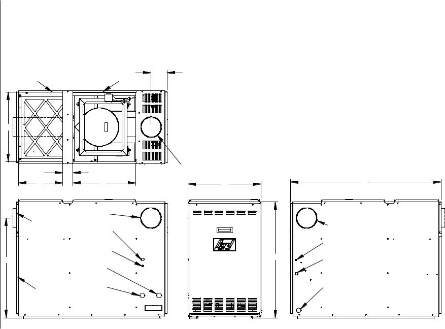
FLF/FLR 085, 110 AND 140 SPECIFICATION SHEET
|
TOP VIEW |
J |
|
RETURN |
SUPPLY |
||
|
|||
DUCT |
|
DUCT |
D
G |
|
F |
E |
|
"FLF" FLUE |
REAR FLUE |
KNOCKOUT |
|
|
ON "FLR" MODELS |
OPTIONAL |
|
HIGH VOLTAGE |
|
ENTRANCE |
OPTIONAL
LOW VOLTAGE
ENTRANCE
H
OIL
ENTRANCE
OPTIONAL
FILTER OIL
DOOR ENTRANCE
FRESH AIR
KNOCKOUT 
LEFT SIDE VIEW
FIGURE 1
FLF/R MODELS DIMENSIONS
TABLE 2
FLF/R MODELS DIMENSIONS (INCHES)
|
|
Cabinet |
|
Plenum |
Flue Conection |
|
Air Filters |
|
|||||
|
|
|
Openings |
|
1 |
||||||||
Model |
A |
B |
|
C |
D x E |
D x F |
Location |
G |
H |
J |
Size |
|
No. |
Number |
Width |
Depth |
|
Height |
Supply |
Return |
Dia. |
|
Used |
||||
FLF085D36E |
23 |
48.125 |
|
36.625 |
22x20 |
22x14 |
Front |
6 |
31.625 |
5.125 |
16 x 20 x 1 |
|
1 |
FLR085D36E |
23 |
48.125 |
|
36.625 |
22x20 |
22x14 |
Rear |
6 |
31.625 |
5.125 |
16 x 20 x 1 |
|
1 |
FLF110D48E |
23 |
48.125 |
|
40.625 |
22x20 |
22x14 |
Front |
6 |
35.625 |
5.125 |
20 x 20 x 1 |
|
1 |
FLF110D60E |
23 |
48.125 |
|
40.625 |
22x20 |
22x14 |
Front |
6 |
35.625 |
5.125 |
20 x 20 x 1 |
|
1 |
FLR110D48E |
23 |
48.125 |
|
40.625 |
22x20 |
22x14 |
Rear |
6 |
35.625 |
5.125 |
20 x 20 x 1 |
|
1 |
FLR110D60E |
23 |
48.125 |
|
40.625 |
22x20 |
22x14 |
Rear |
6 |
35.625 |
5.125 |
20 x 20 x 1 |
|
1 |
FLR140D60E |
26 |
50.250 |
|
47.625 |
25x20 |
25x16 |
Rear |
6 |
42.125 |
- - - |
20 x 25 x 1 |
|
1 |
|
|
|
|
|
|
|
|
|
|
|
|
|
|
j Washable type filter 1” nom. thickness
"FLF" FLUE KNOCKOUT
A |
B |
|
|
"FLF" FLUE |
|
KNOCKOUT |
|
LOW VOLTAGE |
|
ENTRANCE |
C |
HIGH VOLTAGE |
|
ENTRANCE |
|
OPTIONAL |
|
OIL ENTRANCE |
FRONT VIEW |
RIGHT SIDE VIEW |
MIS-1815 A |
Page |
Manual |
4 |
422-2100 |
|
19 1/4" |
|
|
RETURN |
|
16" |
OPENING |
|
(CUT OUT) |
||
|
LEFT SIDE VIEW
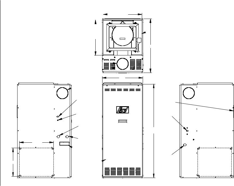
FIGURE 2
FH MODELS DIMENSIONS
TOP VIEW |
|
|
21 7/8" |
|||
|
|
|||||
|
|
|
||||
|
|
|
|
|
|
|
|
|
|
|
|
|
|
|
|
|
|
|
|
|
|
|
|
|
|
|
|
|
|
|
|
|
|
|
|
|
|
|
|
|
|
19 7/8"
FLUE
KNOCKOUT 
23"
FLUE
 KNOCKOUT
OPTIONAL
HIGH VOLTAGE
ENTRANCE
OPTIONAL
LOW VOLTAGE
ENTRANCE
OPTIONAL
OIL
ENTRANCE
OIL
ENTRANCE
 FRESH AIR
KNOCKOUT
VESTIBULE 
DOOR
FH085 AND FH110
SUPPLY SPECIFICATION SHEET
 OPENING
30 1/2"
FLUE
KNOCKOUT 
REAR CLEANOUT
DOOR
HIGH
VOLTAGE
ENTRANCE
53" (FH085) 59" (FH110)
LOW VOLTAGE 
ENTRANCE
OPTIONAL
OIL
ENTRANCE RETURN OPENING (CUT OUT)
FRONT VIEW |
RIGHT SIDE VIEW |
MIS-1814 A |
|
|
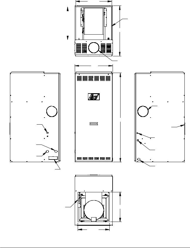
FIGURE 3
FC085 MODEL DIMENSIONS
21 7/8"
FC085 |
|
|
|
|
19 7/8" |
|
|||
SPECIFICATION |
|
|
|
|
SHEET |
|
|
|
|
FLUE
KNOCKOUT
OPTIONAL
HIGH VOLTAGE
ENTRANCE
OPTIONAL
LOW VOLTAGE
ENTRANCE
OIL ENTRANCE
OPTIONAL
OIL ENTRANCE
FRESH AIR
KNOCKOUT
LEFT SIDE VIEW
RETURN
OPENING
SUPPLY
OPENING
30 1/2"
TOP VIEW
FLUE
23" KNOCKOUT
|
FLUE |
|
|
KNOCKOUT |
|
54 1/4" |
REAR |
|
|
CLEANOUT |
|
|
DOOR |
|
|
LOW VOLTAGE |
|
|
ENTRANCE |
|
|
HIGH VOLTAGE |
|
|
ENTRANCE |
|
FRONT VIEW |
OPTIONAL |
|
OIL ENTRANCE |
||
|
RIGHT SIDE VIEW
18 1/8"
BOTTOM VIEW |
|
19 1/8" |
MIS-1826 |
|
Manual 2100-422
Page 5

INSTALLING THE FURNACE
INSTRUMENTS REQUIRED FOR PROPER SETUP OF THE FURNACE
It is important that a set of instruments capable of the following requirements be used for the setup of this furnace to ensure proper and safe operation:
1.Oil pump pressure gauge that measures up to 150 PSI.
2.Smoke gun to pull smoke samples from flue.
3.Draft gauge that will measure -.02” water column (W.C.)
4.Duct static pressure gauge 0-1.0” W.C. range.
5.Temperature gauge that can read from 50° F up to 700° F.
6.A gauge to measure CO2 or O2.
INSTALLATION
A typical installation is shown in Figures 4 and 5. All parts of the furnace installation (furnace, oil tank and piping systems, combustion and ventilation air, venting, etc.) must comply with NFPA31, Installation of Oil Burning Equipment -- latest edition. This drawing shows the typical connecting parts needed to correctly install this furnace. Make sure that all parts of the heating system comply with the local codes.
Check the furnace and your load calculation to verify that the unit is properly sized. (Refer to Equipment Selection” section on Page 2.)
The correct size of unit needed may be substantially smaller than the unit being replaced due to home improvements and technology advancements since the initial installation.
INADEQUATE SUPPLY AIR and/or RETURN AIR DUCT SYSTEMS
Short cycling because of limit control operation can be created by incorrectly designed or installed supply and/ or return air duct systems.
The duct systems must be designed using ASHRAE or ACCA design manuals and the equipment CFM and external static pressure ratings to insure proper air delivery capabilities.
On replacement installations, particularly if equipment is oversized, the duct systems can easily be undersized. Modifications may be required to assure that the equipment is operating within the approved temperature rise range when under full rated input conditions, and that no short cycling on limit controls is occurring.
DUCT WORK
The air distribution system should be designed and installed in conformance with manuals published by Air Conditioning Contractors of America (ACCA) as set forth in Manual D, or ASHRAE publications.
IMPORTANT
When a furnace is installed so that supply ducts carry air circulated by the furnace to areas outside the space containing the furnace, the return air must also be handled by a duct(s) sealed to the furnace casing and terminating outside the space containing the furnace This is to prevent drawing possible hazardous combustion products into the circulated air.
INSTALLING A COOLING UNIT
When the furnace is used in connection with a cooling unit*, the furnace shall be installed parallel with or on the upstream side of the cooling unit to avoid condensation in the heating element. With a parallel flow arrangement, the dampers or other means used to control flow of air shall be adequate to prevent chilled air from entering the furnace, and if manually operated, must be equipped with means to prevent operation of either unit, unless the damper is in the full heat or cool position.
*A cooling unit is an air conditioning coil, heat pump coil or chilled water coil.
When installing a cooling unit above an FH or FL (below on an FC) series furnace, the coil must be spaced far enough from the furnace outlet to assure proper operation of the furnace. Bard supplied coils, when used with Bard supplied coil cabinets, are automatically positioned.
For top discharge FH and FL models, when coils are installed without using Bard coil cabinets or coils of another brand are used, the coil drain pan should be located a minimum of two (2) inches above the top of the furnace cabinet. If a greater clearance is specified by the coil manufacturer then it would apply.
NOTE: IF DRAIN PAN IS ANYTHING OTHER THAN A STEEL PAN PARTICULAR ATTENTION MUST BE GIVEN TO THE INSTALLATION INSTRUCTIONS FOR THE COIL TO MAKE SURE IT IS ACCEPTABLE FOR USE WITH THESE OIL FURNACES HAVING MAXIMUM OUTLET AIR TEMPERATURE OF 200° F.
See CFM versus static pressure curves on pages 33-36 for additional information.
Manual 2100-422
Page 6

WIRING
FACTORY WIRING
All units are fully factory wired. Multispeed blowers are factory wired on high speed for cooling/manual fan operation. Heating speeds are wired for the largest input and may need lower speed for field installed low input nozzle. If replacement wire is necessary, use 105 degrees C minimum. See electrical data, Table 3.
FIELD WIRING
All wiring must conform to the National Electrical Code and all local codes. A separate fuse or breaker should be used for the furnace.
TABLE 3
ELECTRICAL DATA
|
|
|
Blower Motor |
Burner Motor |
|
Max. Time |
|||
|
|
|
Minimum |
Delay Fuse |
|||||
|
|
Total |
HP |
FLA |
HP |
FLA |
Circuit |
or HACR |
|
Model |
Volts-HZ-PH |
Amps |
Ampacity |
Circuit Breaker |
|||||
|
|
|
|
||||||
|
|
|
|
|
|
|
|
|
|
FH085D36E |
115-60-1 |
9.2 |
1/3 |
7.5 |
1/7 |
1.7 |
15 |
15 |
|
FH110D48E |
115-60-1 |
12.2 |
1/2 |
10.5 |
1/7 |
1.7 |
16 |
20 |
|
|
|
|
|
|
|
|
|
|
|
FH110D60E |
115-60-1 |
14.2 |
3/4 |
12.5 |
1/7 |
1.7 |
19 |
20 |
|
FLF085D36E |
115-60-1 |
17.3 |
1/3 |
5.6 |
1/7 |
1.7 |
15 |
15 |
|
|
|
|
|
|
|
|
|
|
|
FLR085D36E |
115-60-1 |
17.3 |
1/3 |
5.6 |
1/7 |
1.7 |
15 |
15 |
|
FLF110D48E |
115-60-1 |
12.2 |
1/2 |
10.5 |
1/7 |
1.7 |
16 |
20 |
|
|
|
|
|
|
|
|
|
|
|
FLR110D48E |
115-60-1 |
12.2 |
1/2 |
10.5 |
1/7 |
1.7 |
16 |
20 |
|
FLF100D60E |
115-60-1 |
14.2 |
3/4 |
12.5 |
1/7 |
1.7 |
19 |
20 |
|
|
|
|
|
|
|
|
|
|
|
FLR100D60E |
115-60-1 |
14.2 |
3/4 |
12.5 |
1/7 |
1.7 |
19 |
20 |
|
FLR140D60E |
115-60-1 |
14.2 |
3/4 |
12.5 |
1/7 |
1.7 |
19 |
20 |
|
|
|
|
|
|
|
|
|
|
|
FC085D36E |
115-60-1 |
7.3 |
1/3 |
5.6 |
1/7 |
1.7 |
15 |
15 |
|
Manual 2100-422
Page 7

WARNING
ALL WIRING MUST
CONFORM TO THE ! NATIONAL ELECTRIC
CODE AND ALL LOCAL
CODES.
Left side high voltage (unit power) entrance
Left side low voltage (thermostat) entrance
Left side oil line entrance for opt. air boot
Left side oil line entrance
Oil line (see burner
pump inst. for hookup info.)
Air Boot knockout (optional)
Control panel (junction box in FH units)
FIGURE 4
TYPICAL UNIT SETUP
FLF UNIT SHOWN
TYPICAL UNIT
SETUP
(FLF UNIT SHOWN)
Right side high voltage
(unit power)
entrance Right side oil line
entrance
Inspection door
Right side low voltage (thermostat) entrance
To thermostat and optional A/C unit
 To power source
 Shut off switch (if not fused, power line must include fuse or circuit breaker)
Power Wires:
Black (HOT)
White (NEUTRAL)
Green (GROUND)
MIS-1836
Manual 2100-422
Page 8
L i n e d
C h i m n e y
Clean-out Door (keep closed)
FIGURE 5
TYPICAL FLUE INSTALLATION REQUIREMENTS FRONT FLUE LOWBOY MODEL SHOWN (REPRESENTS ALL MODELS)
Thimble |
INSTALLER NOTE: |
|
|
||
|
Follow all appropriate |
|
|
standards for installing |
|
|
needed venting system. |
|
|
Draft Regulator |
|
|
(Be sure to follow |
|
|
installation inst. |
|
1/4 inch per |
supplied with |
|
regulator). |
||
1 foot rise |
||
|
||
|
90° Rotatable |
|
|
Flue Box on front |
|
|
flue models |
|
|
(remove appropriate |
|
|
cabinet knockout). |
|
|
Mounting screws |
|
|
located under flue |
|
|
box cover. |
|
|
Flue Box |
|
|
Cover |
Optional
Flue
Locations
Oil Burner
Optional Fresh
Air Boot (remove MIS-1825 rect. knockout).
Manual 2100-422
Page 9
OIL LINE PIPING
First determine whether the pipe system is to be a single line system or a two line system. All connections must be absolutely air tight or you will have a malfunction of the burner. When installing the piping, a good oil filter should be installed close to the burner. A single line system is recommended for gravity feed.
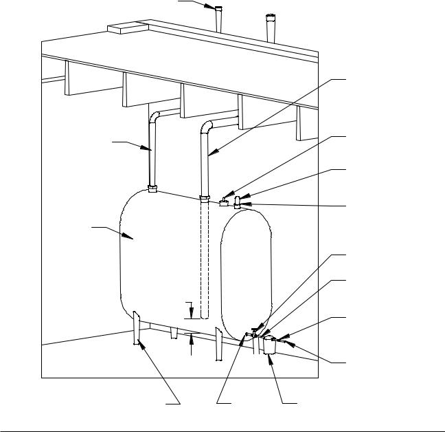
A typical single inside tank installations shown in Figure 6. For installation details for this and other tank configurations, refer to NFPA31 -- latest edition. All tank and pipe setups must comply with NFPA31.
BECKETT AFG OIL BURNER
This furnace is equipped with a high static Beckett AFG oil burner which is designed to produce adequate draft in nearly any vertically vented application. The burner employs the latest time tested controls of the highest quality. The controls consist of a high voltage Beckett solid state igniter, a Beckett “CleanCut” oil pump with an integral solenoid valve, and a Beckett R7184B primary control.
FIGURE 6
TYPICAL SINGLE INSIDE TANK INSTALLATION
Vent Cap
 2" Cap
2" Fill Pipe
1-1/4" |
|
|
Return Line |
Vent Pipe |
|
|
|
|
|
|
|
|
|
|
Guage |
Oil |
|
|
Bushing, |
|
|
2" x 1-1/2" or |
|
Tank |
|
|
|
|
|
1-1/4" |
|
|
|
|
|
|
|
|
Gate Valve |
|
|
|
3/8" x 4" |
|
6" |
|
nipple |
|
|
|
|
|
|
|
3/8" x 3/8" |
|
|
|
Adapter |
|
|
|
3/8" O.D. Copper |
|
|
|
Fuel Tubing |
Legs (either 1-1/4"x10" |
Bushing |
Oil Filter |
MIS-1823 |
or 1-1/2"x10" nipples) |
Manual 2100-422
Page 10
 Loading...