

Page 1
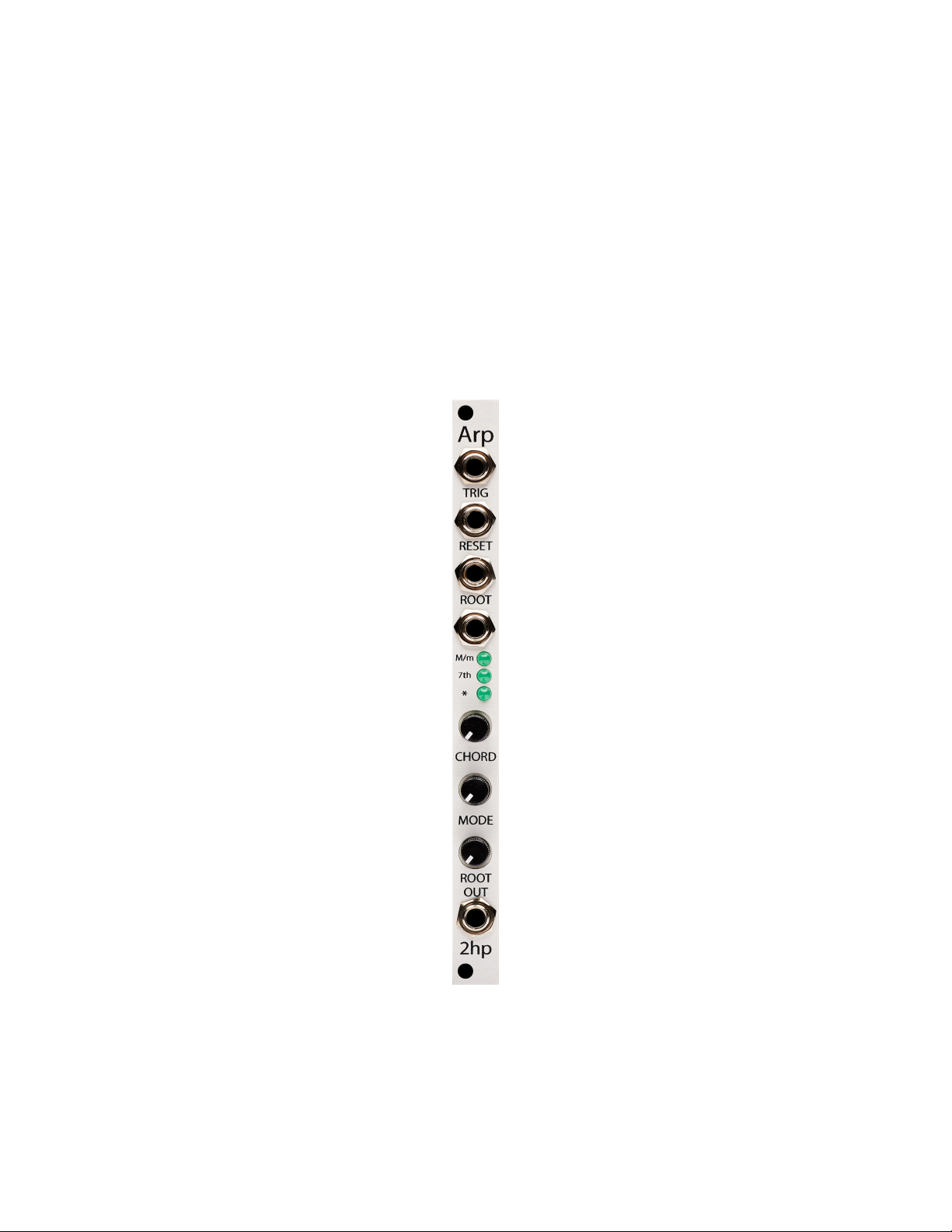
Arp
1
Page 2

Contents
Description 3
Installation 4
Specications 4
Diagram 5
Functional Overview 6
1. Trig Input . . . . . . . . . . . . . . . . . . . . . . . . . . . . . . . . . 6
2. Reset Input . . . . . . . . . . . . . . . . . . . . . . . . . . . . . . . . 6
3. Root . . . . . . . . . . . . . . . . . . . . . . . . . . . . . . . . . . . . 6
3a. Root CV . . . . . . . . . . . . . . . . . . . . . . . . . . . . . . 6
3b. Root Knob . . . . . . . . . . . . . . . . . . . . . . . . . . . . . 6
4. Chord . . . . . . . . . . . . . . . . . . . . . . . . . . . . . . . . . . . . 7
4a. Chord CV . . . . . . . . . . . . . . . . . . . . . . . . . . . . . . . 7
4b. Chord LEDs . . . . . . . . . . . . . . . . . . . . . . . . . . . . . 7
4c. Chord Knob . . . . . . . . . . . . . . . . . . . . . . . . . . . . 8
5. Mode Knob . . . . . . . . . . . . . . . . . . . . . . . . . . . . . . . . 8
6. Out . . . . . . . . . . . . . . . . . . . . . . . . . . . . . . . . . . . . 8
2
Page 3

Description
Arp is a gate-driven arpeggiator with a multitude of chord types and playback modes.
Voltage control over both root note and chord type allow for sequencing any combination of chords in any key imaginable. With the rate of the arpeggio and reset
capability in your own hands, you’re free to create dynamic rhythmic melodies from
your favorite chords. Take your tonality for a ride with Arp.
• Gate-driven arpeggiator
• Multitude of chord types, including triads and sevenths
• Unique playback modes, including random and pendulum
• V/oct tracking on Root CV input
3
Page 4

Installation
To install, locate 2 HP of space in your Eurorack case and confirm the positive 12 volts
and negative 12 volts sides of the power distribution lines. Plug the connector into
the power distribution board of your case, keeping in mind that the red band corresponds to negative 12 volts. In most systems, the negative 12 volt supply line is at
the bottom. The power cable should be connected to the module with the red band
facing the front of the module.
Specications
• Size: 2 HP
• Depth 42mm
• Current Consumption:
– +12V: 40mA
– -12V: 7mA
4
Page 5
Diagram
5
Page 6

Functional Overview
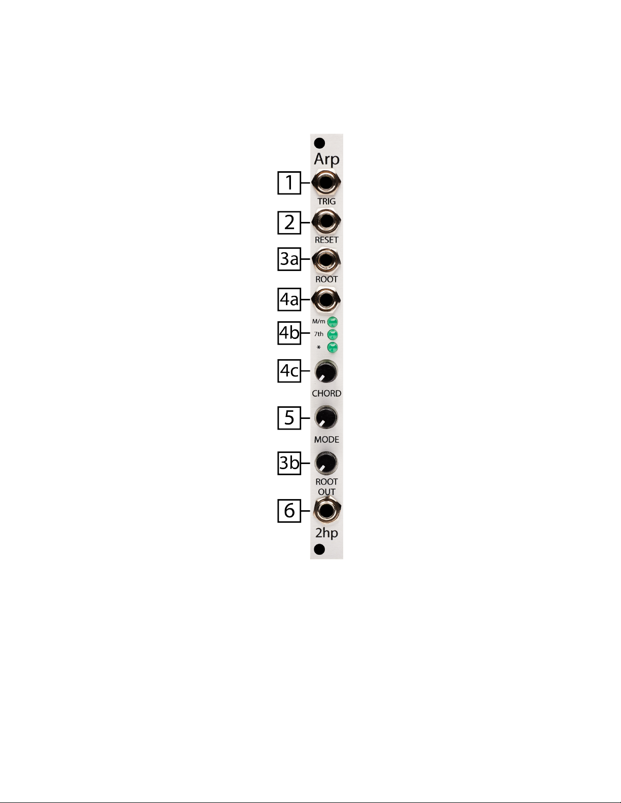
1. Trig Input
A trigger or gate signal present at this input will advance the arpeggio to the next
note
2. Reset Input
A trigger or gate signal present at this input will reset the arpeggio to its root note
3. Root
Sets the initial voltage offset of the output
This can be thought of as the chord’s root note
3a. Root CV
CV input for Root control
Range: 0V to +5V
Control voltage is added to the knob position
3b. Root Knob
When fully left the root will be 0V
When fully right the root will be 5V
6
Page 7

4. Chord
Defines the relationship between the root note and the other notes in the chord
4a. Chord CV
CV input for Chord control
Range: 0V to +5V
Control voltage is added to the knob position
4b. Chord LEDs
Displays the selected chord type
Chord Type M/m LED 7th LED * LED
Major On Off Off
Major 7 On On Off
Dominant 7 On On On
Minor Off Off Off
Minor 7 Off On Off
Diminished Off Off On
Half Diminished 7 Off On On
Full Diminished 7 Off Blinking On
Augmented On Off Blinking
Augmented 7 On On Blinking
Sus 4 Blinking Off Off
Sus 4 Maj 7 Blinking On On
Sus 4 Min 7 Blinking On Off
7
Page 8

4c. Chord Knob
Selects the current chord
When fully left, Major triad will be selected
When fully right, Sus 4 Min 7 will be selected
5. Mode Knob
Sets the playback mode, including range and direction
• Ascending one octave
• Ascending two octaves
• Descending one octave
• Descending two octaves
• Pendulum one octave
• Pendulum two octaves
• Random one octave
• Random two octaves
6. Out
Voltage output for the arpeggio
Range: 0V to +5V
Plug this into 1V/Oct input of a sound generator
8
 Loading...