

Page 1
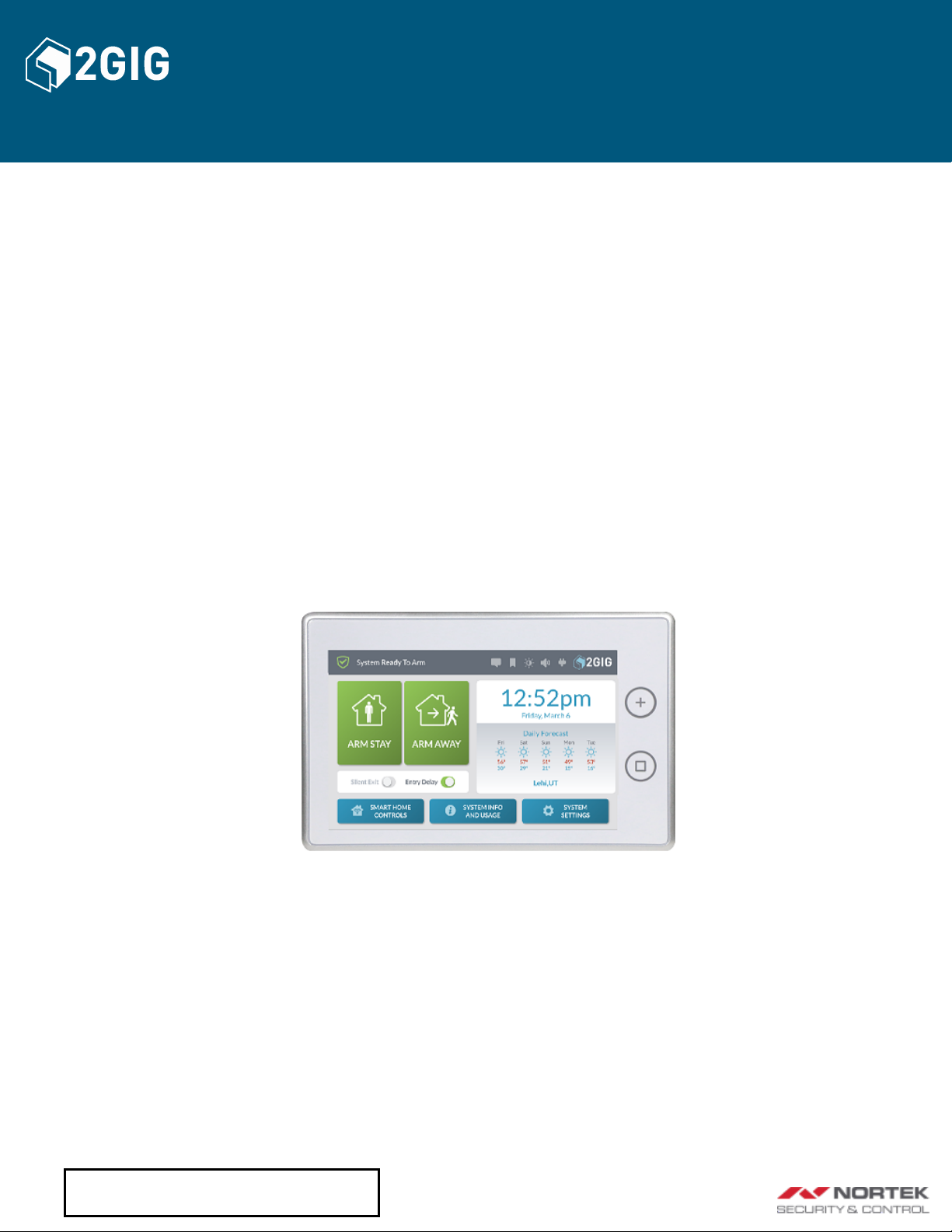
2GIG®GC3 Security & Automation System
800-229-6693
www.HPIsecurity.com
An Authorized Dealer
Call
UserGuide
10004670 A
WARNING: OWNER'S INSTRUCTION NOTICE
Not to be removed by anyone except occupant
Page 2

Copyright © 2016 Nortek Security &Control LLC. All Rights R eserved. U.S. Patent D727,857. Australian Patent No. 357098. Additional Patents Pending.
Covered by one or more claims of patents: http:// sipcol l.com/patent-li st/ andhttp:// intusiq.com/patent-list/.
The 2GIG, GC3, GoControl, and Linear logos areregistered trademarks of Nortek Security &Control LLC in t he U nited States and/or other countries. OtherNortek Security &Control
trademarks may also appear in these materials. Other names or brands may be claimed as the property of others. For more information, contact your 2GIG alarm dealer for pricing or visit
www. nortekinc.com, www.nortekcontrol.com, or http://www. 2gig.com.
This document utilizes the Cue gestural icon system by P.J. Onori, which is available under a Creative Commons Attribution-ShareAlike 3.0 United States (CC-BY-SA-3.0)license.
Information in this document is subject to change without notice. The availability of particular products, services, and features may vary by region. Please check with y our local dealer for
further details and availability of language options.
No part of this publication m ay be reproduced, stored in a retrieval system, or transmitted in any form or any means electronic or mechanical, includingphotocopying and recording for any
purpose other than the purchaser's personal use without the writ ten permission of Nortek Security &Control.
Nortek Security &Control
1950 Camino VidaRoble, Suite 150
Carlsbad, CA92008-6517
USA
800-421-1587
Page 3

CONTENTS
1 INTRODUCTION
About thisGuide 6
Document Conventions 6
Technical Support 6
2 SYSTEMOVERVIEW
System Features and Capabilities 8
AdditionalAccessories 8
Setup and Installation 9
Operational Concepts 9
Features to Limit F alse Alarms 10
Use and Care of the System 12
Limitationsof Alarm Products 12
3 TOUCHSCREEN BASICS
Waking the Touchscreen 14
About the Home Screen 14
System Status Messages 15
System Icons 15
Using the Inbox 16
Using Bookmarks 18
System Logo 18
Viewing the Weather Forecast 19
Using the System Menus 20
Responding to Trouble Alerts 21
4 BURGLARY PROTECTION
Overview 24
Important Concepts 24
Sample Burglary Alarm Plan 25
Arm the System 26
Force Bypassing 27
Use the Quick ExitButton 28
In the Event of an Exit Error 29
To Disarm the System 29
Transmit a User Duress Report 30
In the Event of a Burglary Alarm 30
5 FIRE &CARBON MONOXIDE PROTECTION
Overview 34
Important Concepts 34
National F ire Alarm and Signaling Code 34
Recommended Smoke Alarm Placement 34
Emergency Action Plan 35
In the Event of a Fire Alarm 35
Silence aFalse Fire Alarm 35
In the Event of a Carbon Monoxide Alarm 35
Clear the Alarm History 36
Copyright © 2016 Nortek Security &Control LLC 3
Page 4
Table of Contents Proprietary &Confidential
6 EMERGENCY FEATURES
24-Hour Alarm Buttons 38
Activate a Manual Panic,Fire, or Emer gency Alarm 38
7 REMOTE CONTROL
Remote Control Devices 40
Operate the System with a Key Fob 40
8 SMART HOME CONTROLS
About the Smart Home Controls Menu 42
Navigate to the Smart Home Controls Menu 42
Lights 42
Locks 42
Thermostats 42
Scenes 43
Add a NewRoom 45
9 SYSTEM INFO AND USAGE
System Info and Usage 50
History 50
System Info 51
Dealer Info 51
10 SYSTEMSETT INGS
Users 54
Sounds 58
BypassSensors 59
Smart Home Settings Menu 60
Screen 70
Date/Time 72
SystemTests 72
FirmwareUpdate 74
Replace the GC3 Cellular Radio Module 75
Index 79
4 Copyright © 2016 Nortek Security &Control LLC
Page 5

1 INTRODUCTION
Before you get started, review the following information:
Abo ut th is Guide 6
Docu ment Con vention s 6
Technical Supp ort 6
Copyright © 2016 Nortek Security &Control LLC 5
Page 6
1 Introduction Proprietary &Confidential
About this Guide
This guide is designed for end users of the GC3 Security & Automation
System. It provides general system information, safety precautions, and
step-by-step instructions for operating the system. It is intended for use
only by GC3 Security & Automation System owners whose system has
been professionalinstalled ina residentialor commercial setting byan
authorized 2GIGalarm dealer.
For a list of 2GIG alarm dealers and distributors in your ar ea, visit:
www.nortekcontrol.com or www.2gig.co m.
Document Conventions
This section describes the document conventionsused in thisguide.
Safety Precautions and Notations
It is imperativethat you observe all of the safety precautions documented
in this guide. For your safety and the safety of others, the table below
detailshow this guide calls specialattention to information intended to
safeguard life, health, and property.
DANGER!!! This notation is used to indicate hazardous
situationswhich, if not avoided, will r esult in serious injury or
death.
WARNING!! This notation is used to indicate potentially
hazardous situations which, if not avoided, could result in
serious injury or death.
CAUTION! This notation is used to indicate a potentially
hazardous situation which, if not avoided, could result in
minor or moderate injury.
IMPORTANT: This notation is used to indicate a situation
which, if not avoided, could result in property damage,
equipment damage, or data loss.
NOTE: This notation is used to callattention to notable
information that should be followed when installing, servicing,
or using this pr oduct.
TIP: This notation is used to call attention to helpful hints
related to using the product.
Touchscreen Navigation
This table describes the action words used to inform users of methods for
touchscreen navigation.
Table 1-1 Touchscreen Navigation
Glyph…
Typographic Conventions
The following typographic conventions are used to call attention to specific
words and phrases:
Actio n
Word…
Tap (or
single tap)
Touch and
hold
Swipe
down
Bold Highlights key information in list bullets and draws attention
to words, phrases, and text encountered on the touchscreen's
user interface. For example, "open the Syst em Settings menu"
or "swipe up and then tap the System Info button."
Monospace Denotes words, phrases, and text that must be
manually entered bya user through the touchscreen's keypad.
For example, enter the user code 1234to access the System
Settings menu.
Italics Denotes the names of variable information and optional
settingsthat can be selected or entered using the touchscreen. It
is also used to refer readers to other Nortek Security &Control or
2GIG product documentsthat you can read for more information.
Dagg er (†) Indicatesthat a specificsetting or value is a factory
default setting or value. The setting or value on your particular
system may be different.
Glyph… Actio n Word…
Swipe left
Swipe right
Swipe up
Technical Support
Should you require technicalsupport for thissystem, please contact your
2GIG alarm dealer or your Remote Service Provider. If your dealer or
provider cannot immediately answer your inquiry, the dealer should
forward a service query to Nortek Security &Control using the appropriate
channel.
6 Copyright © 2016 Nortek Security&Control LLC
Page 7

2 SYSTEMOVERVIEW
This chapter includes the following information:
System Features and Cap abilities 8
Add itio nal Accessories 8
Setup an d Installation 9
Operational Concepts 9
Features t o Limit F alse Alarms 10
Use an d Care of t he System 12
Limitations of Alarm Products 12
Copyright © 2016 Nortek Security &Control LLC 7
Page 8

2 SystemOverview Proprietary &Confidential
System Features and Capabilities
If you're familiar with other 2GIG Control Panels, you'll notice the new GC3
Panel from Nortek Security&Control offers the very best components of
the GC2 Panel and has been transformed by a major visual upgrade—
offering a larger touchscreen and an intuitive user interface featuring
convenient, gesture- based navigation.
Figure 1 GC3 Control Panel—Front View
Features
The system includes:
Touchscreen Display: A large, full-color, 7-in ( 17.8 cm)
diagonal touchscreen with an intuitive, gesture-based user
interface.
Piezo Sound er and Internal Speaker: An 85 dBPiezo
Sounder sounds external alarms. An internal speaker to delivers
voice annunciations, chimes, other system notifications.
CAUTION! Long or repeated exposure to sounds
at or above 85 dB can lead to Noise-Induced
Hearing Loss (NIHL).
Alarm Butto n/L EDIndicator:Tap this button to show Panic,
Fire, and Emergency buttons. For more information, see the
GC3 Security & Automation System Fingertip Guide.
Home Button /LEDIndicator: A button to wake the
touchscreen and give users the abilityto return to the
touchscreen's Home screen. For more information, see the GC3
Security & Automation System Fingertip Guide.
Removable Faceplate: A removable faceplate concealing a
door lockfor the Cellular Radio Module bay.
Microphone and Speaker: A built-in microphone and speaker
provide clear 2-Way Voice communication during alarm events
between users at the GC3 Paneland operators at the Central
Station.
Cellular Radio Modu le with In ternal Antenna: A snap-in
Cellular Radio Module with an internal antenna that fits neatlyin
the side panel.
24-Ho ur Backup Bat tery: A 24-hour backup battery to support
the GC3 Panel during temporary AC power failures and outages.
USBPort: Aconvenient USB port at the top of the GC3 Panel
that can be used with a USBthumb drive (not supplied)to update
the system's firmware.
Capabilities
The system includes these capabilities:
Security Cod es: The system supports a maximum of 100
unique, programmable, security codes for accessing system
functions. You are provided with one (1) Master User Code, one
(1)Duress Code, and one (1)Installer Code (reserved for use by
2GIG alarm dealers and installers), and the abilityto create 98
additional user codes for accessing the system.
Z-Wave®and Z-Wave Plus™ Compatibility: Installers (and
end users, if configured on the system)can add up to 232 smart
home devices to communicate with the GC3 Panel using the ZWave and Z-Wave Plus wirelesscommunication protocol. The
GC3 Panelcan be included and operated inany Z-Wave network
with other Z-Wave certified devices from other manufacturers
and/or other applications. All non-battery operated nodes within
the network will act as repeaters regardless of vendor to increase
reliability of the network. This device is a security enabled Z-Wave
Plus product that is able to use encrypted Z-Wave Plus messages
to communicate to other security enabled Z-Wave Plus products.
2-Way Voice: (Optional) Operators at the Central Station can
communicate directly with end users through the GC3 Panel .
Operators can also silentlylisten-in after receiving a user duress
report.
Date, Time, and Weather Forecasts1: Users can view the
current date, time, and weather forecast in an easy-to-read
format.
System Vocabulary/Voice Descriptors: A list of vocabulary
words integrates with the on-screen user interface and audio
announcements. This lets installers customize the sensor names
that display on the GC3 Panel , as well as for the audible system
announcements.For example, when someone opens the front
door, the system can be set up to announce "fr ont door."
Additional Accessories
The installer typicallysets up the system to communicate with a variety of
wired and/or wireless sensors. Some sensors are visible on the wall or
ceiling. For example, Wireless Smoke/Heat/Freeze Alarms and Wireless
Carbon MonoxideDetectors. Others may be hidden in door jambs . For
example, Recessed Door/Window Contacts. Sensors might also be
installed in additionallocations. For example, a Glass Break Detector and
a Passive Infrared Motion Detector.
NOTE: A variety of 2GIG and GoControl branded devices
are compatible with the GC3 Security & Automation System.
Sensors manufactured by other companiesmay also be
compatible with the system. For information, visit
dealer.2gig.co m.
1
Date,Time and Weather Forecasts are supported by m ost Remote Service Providers in most
regions. Consult your provider to determine if this feature is enabled.
8 Copyright © 2016 Nortek Security&Control LLC
Page 9
Proprietary &Confidential 2 SystemOverview
IMPORTANT: To ensure that your system's sensors are
operating properly, it is important to test all sensors. Consult
your installer to determine the schedule for testing your
sensors.
Z-Wave Smart Ho me Controls
Consult your 2GIG alarm dealer for information about installing a wide
variety of compatible Z-Wave smart home controlsincluding:
Lights
Locks
Thermostats
Setup and Installation
The GC3 Security & Automation System must be installed bya qualified
technician who is either employed by, or under contract with, a 2GIG alarm
dealer. The alarm must always be installed in accordance with your
country's national electrical installation regulationsand/or all applicable
codes in the local jurisdiction.
Operational Concepts
Understanding these conceptswill help you operate the system:
24-Ho ur Alarm Buttons
An installer can configure the GC3 Panel to show or hide three 24-hour
alarm buttons on the touchscreen: Panic, Fire, and Emergency. When
the buttons are enabled and visible, users can manuallytrigger an alarm
from the GC3 Panel. Alarms can also be activated from a wirelesskeypad
(if installed), from wirelesssensors, or from portable devices (for example,
a Panic Button Remote). See "Emergency Features" on page 37.
Alarm
When the system detects an alarm condition, itimmediately sounds an
audible alarm that continuesfor a preset amount of time. If external alarm
sounders or Z-Wave sirens have been installed, thosedevicesalso sound
an audible alarm. During an alarm (and also after a user cancels or clears
the alarm), the Alarm Histo ry revealsa chronological list of the alarms
that have occurred by zone. The next time you arm the system, the system
automaticallyclears the history. You can also manually clear the history.
See "Clear the Alarm History" on page 36.
Fire an d Gas Protection
Fire and gas protection are provided by a combination of Wireless Carbon
MonoxideDetectors and WirelessSmoke/Heat/Fr eeze Alarms that
protect your dwelling 24 hours-a-day. When an alarm condition is
detected, the system sounds an alarm and transmits a report to the
Central Station so operators can dispatch the appropriate emergency
services. See "Fire &Carbon Monoxide Protection" on page 33.
Sensor Types
When programming the sensor into the system, the installer sets the
sensor type for each device.This determines how and when the system
willreact when a sensor detects a an alarm condition. F ire protection
sensors protect the dwelling 24-hours a day, whereas burglary protection
sensors only protect the premiseswhen the system is armed.
Trou ble Alerts
The system monitors itself for abnormal operating conditions and alerts
you when trouble is detected. Examples of alert conditions include
ACpower loss at the GC3 Panel, low battery conditions at a sensor, and
more. See "Responding to Trouble Alerts" on page 21.T he installer can
configure the system to transmit a variety of trouble alerts to the Central
Station.
Wired an d Wireless Sensors
Your system can be installed with wired sensors, wireless sensors, or a
combination of both. Some sensors are visibleon the wall or ceiling (for
example, Wireless Smoke/Heat/Freeze Alarms and WirelessCarbon
MonoxideDetectors), while others may be hidden in doorjambs (for
example, Recessed Door Contacts). Sensors can also be mounted in
different locations (for example, GlassBreak Detectors and Passive
Infrared Motion Detectors).
Zones
The system’s wired and/or wirelesssensors that have been programmed
by the installer are also sometimes r eferr ed to aszones. Examples of
zones that are typically set up for a home installation include Front Door,
Sliding Glass Door , Living Room Bay Window, and so on.
Burglary Protectio n
Burglary protection is provided by a combination of perimeter and interior
sensors installed on doors, windows, and other areas of a dwelling. See
"Burglary Protection" on page 23.
Security Cod es
The system supports a maximum of 100 unique security codes. There are
four types of securitycodes supported by the system:(1)Master User, (2)
User, (3)Duress, and (4)the Installer Code, which is r eserved for use by
2GIG alarm dealers and installer. See "Users" on page 54.
Copyright © 2016 Nortek Security &Control LLC 9
Page 10
2 SystemOverview Proprietary &Confidential
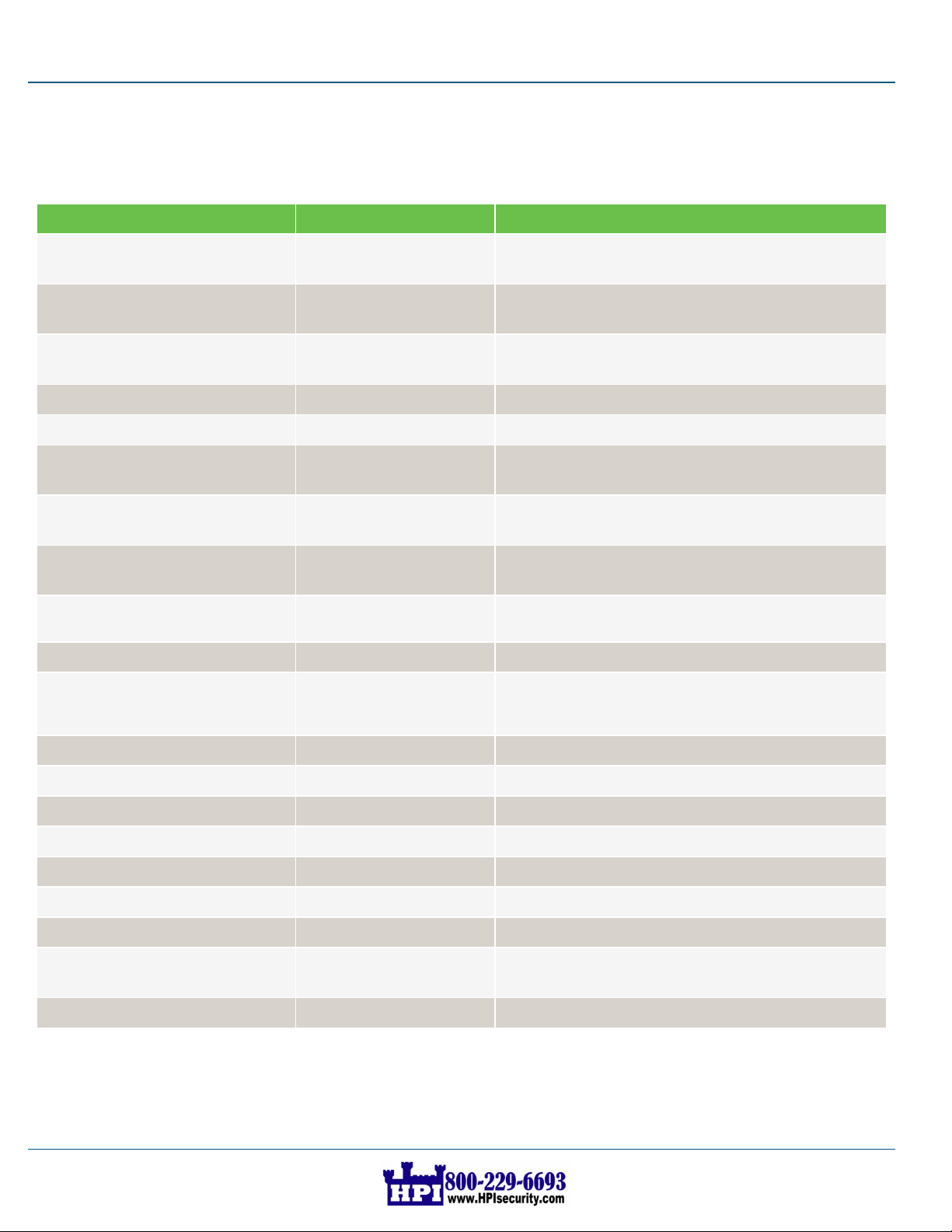
Features to Limit False Alarms
For compliance with ANSI/SIA CP-01-2010: Control Panel Standard - F eatures for False Alarm Reduction, the installer can set a variety of different options
designed to limitoccurrences of a False Alarm.
Table 2-1 ANSI/SIA CP-01-2010 Features to Limit False Alarms
ANSI/SIA CP-01-2010 2GIG System Feature UserGuide
4.2.2.1 Exit Time ExitDelay "Important Concepts" on page 24
"Arm the System" on page 26
4.2.2.2 Progress Annunciation ExitDelay Announcement
4.2.2.3 Exit Time Restart ExitDelay Restart "Important Concepts" on page 24
4.2.2.4 Exit Error ExitError "In the Event of an Exit Error" on page 29
4.2.2.5 Unvacated Premises Auto Stay "Arm the System (Away Mode)" on page 26.
4.2.3.1 Entry Delay Entry Delay
4.3.2.2 Progress Annunciation Entry DelayAnnouncement "Important Concepts" on page 24
4.3.2.3 Disarm Disarming Features
4.2.4.1 Control Buttons Keyfob/Remote Arming Mode on
System Not Ready
4.2.4.2 Manual Alarms Emergency Alarm Featur es "Activate a Manual Panic,Fire, or Emergency Alarm" on page 38
4.2.4.3 System Acknowledgment Alert Keyfob Disarming After
Alarm, Keyfob Arm/Disarm
Confirmation
"Important Concepts" on page 24
"Arm the System" on page 26
"Arm the System" on page 26
"Important Concepts" on page 24
"To Disarm the System" on page 29
"To Disarm the System" on page 29
"Important Concepts" on page 24
"To Disarm the System" on page 29
"Remote Control Devices" on page 40
"Arming the System Using a Keyfob" on page 40
"Disarming the System Using a Key Fob" on page 40
4.2.4.4 Remote Arming KeyFob Arming "Arming the System Using a Keyfob" on page 40
4.3.4.5 RemoteDisarming Key Fob Arming "Disarming the System Using a Key Fob" on page 40
4.2.5.1 Abort Window Abort Window Dialer Delay "In the Event of a Burglary Alarm" on page 30
4.2.5.1.1 Disarm Abort Window Dialer Delay "In the Event of a Burglary Alarm" on page 30
4.2.5.1.2 Abort Abort Window Dialer Delay "In the Event of a Burglary Alarm" on page 30
4.2.5.2 Alarm Transmission Abort Window Dialer Delay "In the Event of a Burglary Alarm" on page 30
4.2.5.3 Disarm Disarm "To Disarm the System" on page 29.
4.2.5.4 Cancel Window Alarm Cancel Time, Alarm Cancel
Display
4.2.6.1 Use of Duress Feature User Duress Report "Transmit a User Duress Report" on page 30.
10 Copyright © 2016 Nortek Security &Control LLC
"In the Event of a Burglary Alarm" on page 30
"Silence aFalse Fire Alarm" on page 35
Page 11

Proprietary &Confidential 2 SystemOverview
ANSI/SIA CP-01-2010 2GIG System Feature UserGuide
4.2.6.2 Duress Code Duress Code "Types of User Codes" on page 54
"Users" on page 54.
4.2.7 Initiation of Manual Alarms Panic, Fire, or Emergency Alarm "Activate a Manual Panic,Fire, or Emergency Alarm" on page 38.
4.3.1 Cross Z oning Cr oss Sensor Zones, Cross
Sensor Timeout
4.3.2 Swinger Shutdown Swinger Shutdown Count (1-6)
4.3.3 Fire Alarms Fire &Carbon Monoxide
Protection
4.6.3 SystemTest
Console T est
Sensors T est
"Q26:Cross sensor zones(99-100)" on page58 of the GC3
Installation & Programming Guide.
"Q27:Cross sensor timeout, in seconds(10-120)" on page59 of the
GC3 Installation & Programming Guide.
"Q25: Swinger shutdown count (1-6)" on page58 of the GC3
Installation & Programming Guide.
"Fire &Carbon Monoxide Protection" on page 33
"SystemTests" on page 72
Copyright © 2016 Nortek Security &Control LLC 11
Page 12
2 SystemOverview Proprietary &Confidential
Use and Care of the System
To care for the system, observe the following:
Humidit y an d Liquids Do not exposethe system to water, rain,
extreme humidity,perspiration, or other liquids. T he optimum
humidity range for the system is 9-90% non-condensing.
Extreme Heat or Cold Do not expose the system to extreme
heat or cold. The optimum operating temperature range is 32° to
120° F (0° to 49° C).
Shock and Vibration F or optimum protection against shock
and vibration, make sure that your installer has securely mounted
the touchscreen flush against the wallor properly installed it in a
compatible desktop kit.
IMPORTANT: To prevent touchscreen damage during
cleaning, see "Screen" on page 70.
Limitations of Alarm Products
This security system cannot offer guaranteed protection against burglary,
fire, or other emergencies. Any alarm, whether commercial or residential,
is subject to compromise or failure to warn for a variety of reasons. For
example:
Intruder s may gain access through unprotected openings or have
the technical sophistication to bypass an alarm sensor or
disconnect an alarm warning device.
Intrusion detectors (sensors) do not work without power. Battery
operated devicesdo not work without batteries, with dead
batteries, or if the batteries are not put in properly. Devices
powered solely by AC do not work if their AC power supplyis cut
off for anyreason, however briefly.
signalssent by wirelesssensors may be blocked or reflected by
metal before theyreach the alarm Control Panel, even if the
signalpath has been recently checked during a weekly test.
Blockage can occur if a metal object has been moved into the
sensor's signal path.
A user may not be able to reach a panic or emergency button
quickly enough.
Telephone linesneeded to transmit alarm signalsfrom a
premises to a Central Station may be out of service or temporarily
out of service. T elephone lines are also subject to compromise by
sophisticated intruder s.
Even if the system responds to the emergency as intended,
however, occupants may have insufficient time to protect
themselvesfrom the emergency situation. In the case of a
monitored alarm system, authoritiesmay not respond
appropriately.
Alarm warning devices such assirens, bells, or horns maynot
alert people or wake up sleepers if they are located on the other
side of closed or partly open doors. If warning devices sound on a
different levelof the residence from the bedrooms, then theyare
lesslikely to waken or alert people inside the bedrooms. Even
persons who ar e awake maynot hear the warning if the alarm is
muffled from a stereo, radio, air conditioner, or other appliance,
or by passing tr affic. F inally, alarm warning devices, however
loud, may not warn hearing-impaired people or awaken deep
sleepers.
While smoke detectors have played a key role in reducing
residential fire deaths, theymay not activate or provide early
warning for a variety of reasons in as many as 35% of all fires,
according to data published by the Federal Emer gency
Management Agency. Some of the reasons smoke detectors
used in conjunction with this system may not work are where
smoke cannot reach the detectors, such as in chimneys, in walls,
or roofs, or on the other side of closed doors. Smokedetectors
may have been improperly installed and positioned. Smoke
detectors also may not sense a fire on another level of a
residence or building. Asecond floor detector, for example, may
not sense a first floor or basement fire. Moreover, smoke
detectors have sensing limitations.No smoke detector can sense
every kind of fire every time. In general, detectors may not always
warn about fires caused by carelessnessand safety hazards like
smoking in bed, violent explosions, escaping gas, improper
storage of flammable materials, overloaded electricalcircuits,
children playing with matches, or arson. Depending upon the
nature of the fire and/or the locations of the smoke detectors, the
detector, even if it operates asanticipated, may not provide
sufficient warning to allow occupants to escape in time to prevent
injury or death.
This equipment, like other electrical devices, is subject to
component failure. Evven though this equipment is designed to
last as long as ten years, the electronic components couldfail at
any time.
The most common cause of an alarm system not functioning when an
intrusion or fire occurs is inadequate maintenance.
Although installing an alarm system may make homeowners eligible for
lower insurance rates, an alarm system isnot a substitute for insurance.
Homeowners, property owners, and renters should continue to act
prudently inprotecting themselves and continue to insure their lives and
property.
12 Copyright © 2016 Nortek Security &Control LLC
Page 13

3 TOUCHSCREEN BASICS
This chapter includes the following information:
Waking the Touchscreen 14
Abo ut th e Home Screen 14
System Stat us Messages 15
System Icons 15
Using the Inbox 16
Using Bookmarks 18
System Logo 18
Viewing the Weather Fo recast 19
Using the System Menus 20
Responding to Trouble Alerts 21
Copyright © 2016 Nortek Security &Control LLC 13
Page 14
3 Touchscreen Basics Proprietary &Confidential
Waking the Touchscreen
During periods of inactivity, the touchscreen automatically times out and
enters sleep mode. To place it into full-power mode, you mustwake the
touchscreen.
To wake the touchscreen:
Tap any ar ea on the
touchscreen.
OR
Press the Home
button to the right of
the touchscreen.
Figure 1 Wake the Touchscreen
TIP: The touchscreen goes into sleep mode after one (1)
minute of inactivity. T o change this setting to between 30
seconds and 10 minutes, tap System Settings, enter the
Master User Code, tap Screen , and then change the
Screen T imeout setting.
This r eveals the Home
screen. See "About the Home
Screen" below.
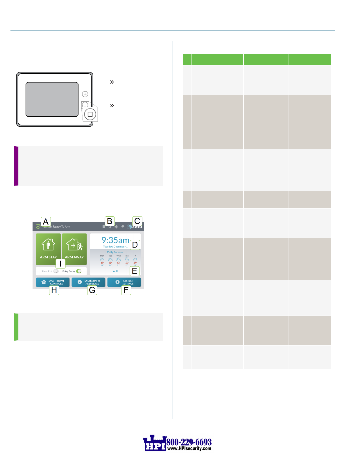
About the Home Screen
When you first wake the system, it revealsthe Home screen.
Table 3-1 Home Screen Features
This feature… Does this… To learn more…
A System Status
Messages
B System Icons
C System Logo Tap the logo and
D Date/Time
E Weather Forecast View the current
Reveals the current
system state.
Provides access to
messaging
features,
bookmarks,
brightness/volume
controls, and
displays the current
power source.
then enter the
Duress Code to
transmit a User
Duress signal to the
Central Station.
View the current
date/time.
weather forecast
(when enabled for
your system).
See "System
Status Messages"
on the facing
page.
See "System
Icons" on the
facing page.
See "System
Logo" on page 18.
See "Date/Time"
on page 72.
See "Viewingthe
Weather
Forecast" on
page 19.
Figure 2 Home Screen Features
NOTE: Access to some features is restricted. To gain access
to a restricted feature, you must know the four-digit Master
User Code. See "Users" on page 54.
Gives anyone who
knows the Master
F System Settings
G System Info and
Usage
H Smart Home Controls
I Security Features Lets users
User Code access
to a variety of
general system
settings.
View general
System
Information ,
Histo ry, and
Dealer In fo.
Access your
system's smart
home controls.
arm/disarm the
system.
See
"SystemSettings"
on page 53
See "System Info
and Usage" on
page 50.
See "About the
Smart Home
Controls Menu"
on page 42.
See "Arm the
System" on page
26.
14 Copyright © 2016 Nortek Security &Control LLC
Page 15
Proprietary &Confidential 3 Touchscreen Basics
System Status Messages
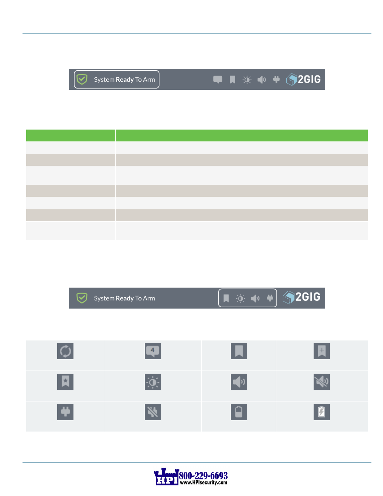
At the top-left of the screen, different messagesappear to reveal the current system state.
Figure 3 System Status Messages
This table describes the different system status messageson the system.
Table 3-2 System Status Messages
This system status message… Indicates that…
System Read y T o Arm Indicates all sensors are closed and the system isready to be armed.
System Not Ready to Arm One or more sensors are open.
SystemReady To Arm (BYPASS) The system is ready to arm and one or more sensors ar e on the Bypassed Sensors list. See "Force Bypassing" on
page 27.
System Arming (STAY) The system is in the processof arming itself in StayMode.
System Arming (AWAY) The system isin the process of arming itself in Away Mode.
System Armed The system isarmed and protecting the premises.
Restarting SecurityProcess The securitysystem is restarting. Typically, this onlyappears after an installer modifiesa System Configuration
setting.
System Icons
The status bar that appears on the top of the Home screen and on most system menus reveals a variety of icons providing system information and access to
different functions.
Figure 4 System Status Bar
Table 3-3 System Icons
USBUpdate Incoming Messages No Bookmark Add Bookmark
Go to Bookmark Dim T ouchscreen System Volume ON Non-Critical Sounds OFF
System on ACPower System NOTon ACPower Low Backup Battery Battery Charging
Copyright © 2016 Nortek Security &Control LLC 15
Page 16

3 Touchscreen Basics Proprietary &Confidential
Using the Inbox
There are three (3)typesof messages that arrive in the Inbox:Alerts,
Alarms, and Messages. When a new message arrives, the Messages
system icon at the top of the screen blinks and shows the number of new,
unread messages. When a new message arrives, the system emits three
(3)beeps once every minute until the message isr ead.
Figure 5 Messages System Icon
Reading Alert Messages
To read an alert message:
1. Tap the Un read Messages system icon.
2. In the drop-down menu, tap Alerts.
Reading Incoming Messages
Your securityprovider has the abilityto transmit messages about system
upgrades, additional services,specialregional weather alerts, and so on.
When transmitting messages to your system, your security provider can:
Mark a Message as Pub lic o r Private: Apublicmessage can
be read byany user. A private message can onlybe opened by
users who know the Master User Code.
Classify a Message as High or Low Priority: Message
classified by the sender as High priority messages appear in
YELLOW. Low priority messages appear in GRAY.
Specify When or If Messages Expire: There is no enforced
limit on the number of messages that you can keep in the Inbox.
However, messages that havebeen set to expire will be
automaticallyremoved from the Inbox at the time and date
specified bythe sender.
To read messages sent byyour securityprovider:
1. Tap the Un read Messages system icon.
2. In the drop-down menu, tap Messages.
Figure 8 Messages >Reading Messages
Figure 6 Unread Messages >Alerts
The system reveals the alert messages.
Reading Alarm Messages
If the system goes into an alarm state, a message issent to the Inbox.
To read an alarm message:
1. Tap the Un read Messages system icon.
2. In the drop-down menu, tap Alarms.
Figure 7 Unread Messages >Alarms
NOTE: If a user duress report has been transmitted
to the Central Station, a notification message about
the silent alarm is not sent to the Inbox. See
"Transmit a User Duress Report" on page 30.
The system reveals the alarm messages.
This r eveals the Messages screen.
3. Before opening the message, it helpsto understand the following:
If a message was marked bythe sender asLow priority,
it appears in GRAY.
If a message was marked bythe sender asHigh priority,
it appears in YELLOW.
If a message was marked asprivate, a lock icon appears
next to the message.
Figure 9 Messages—Priority and Security
4. Tap the desired message to open it.
5. If the message was marked as private, enter your system's fourdigit Master User Code.
16 Copyright © 2016 Nortek Security &Control LLC
Page 17

Proprietary &Confidential 3 Touchscreen Basics
1. Open the desired message.
2. After reading the text, tap Mark as Unread.
Figure 10 Enter Your Code to Read the Message
6. When the message appears, read the text.
Figure 11 Reading a Message
Marking a Message as Read
After reading a message, the system automatically marks the message as
read. You can alsomanually mark the message asread.
To mark a message as read:
1. Open the desired message.
2. After reading the text, tap Mark as Read .
Figure 13 Messages>Mark as Unread Button
The system marks the message as unread.
Deleting a Messag e
If youwant to permanently r emove a message from the Inbox,you can
delete it.
To delete a message:
1. Open the desired message.
2. After reading the text, tap Delete.
Figure 14 Messages>Delete Button
The system deletes the message from the Inbox.
Figure 12 Messages>Mark as Read Button
The system marks the message as read.
Marking a Message as Unread
If youwant to keep a message in the unread status after reading it, you
can mark the message as unread.
To mark a message as unread:
Copyright © 2016 Nortek Security &Control LLC 17
Page 18
3 Touchscreen Basics Proprietary &Confidential
Using Bookmarks
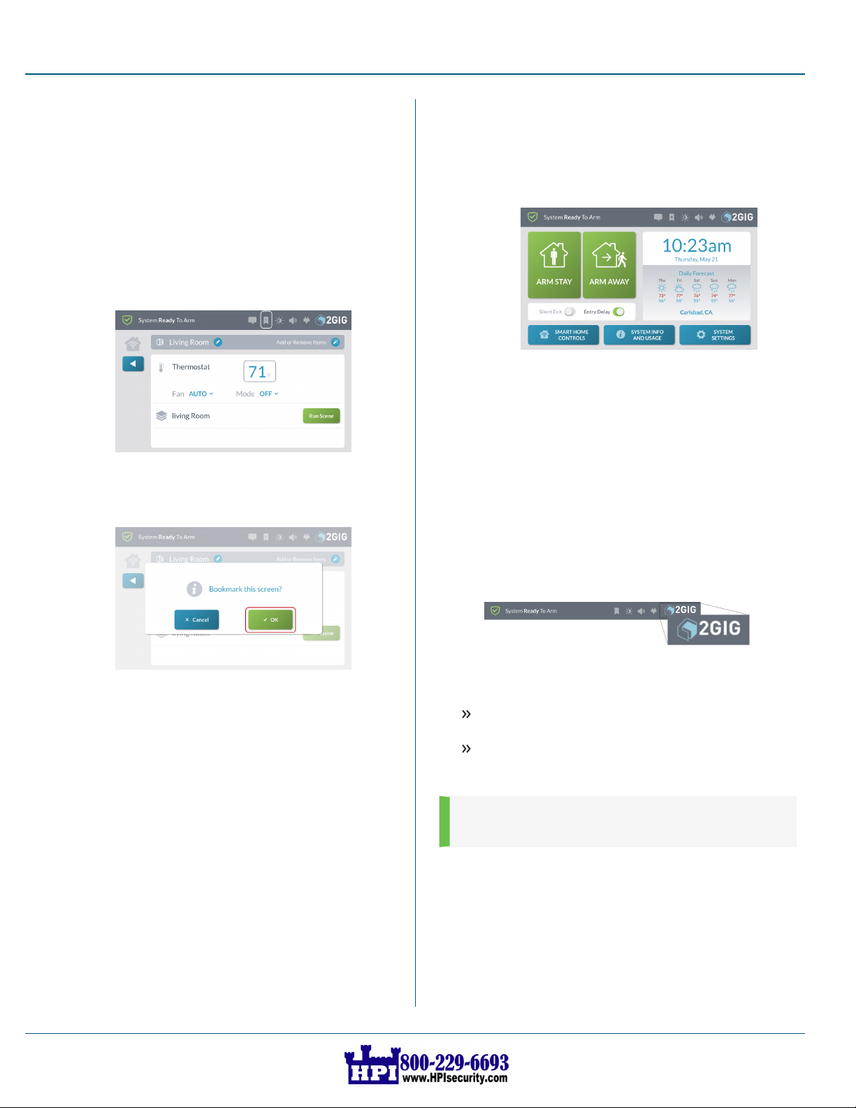
If youfrequently navigate to a particular screen, you can bookmark it which
willmake it the default home screen. The system letsyou bookmark one
(1)screen. This feature istypicallyused to bookmark a room.
Boo kmarking a Screen
To bookmark a screen:
1. Navigate to the desired screen.
For example, tap Smart Home Controls. Then tap Rooms and
then tap on a Room you have created.
2. Tap the Ad d Boo kmark system icon.
Figure 15 Add Bookmark System Icon
3. At the Bookmark this screen?message, tap OK.
Openin g a Bookmarked Screen
If youhave bookmarked a frequently used screen, a star appears on the
system icon.
To go to the bookmarked screen:
1. Tap the Open Bo okmark system icon.
Figure 17 Open Bookmark Icon
The system opens the bookmarked screen.
Clearing a Bookmark
To clear a bookmark from a screen:
1. Navigate to the Home screen.
2. Pressand hold the bookmark icon untila Clear Boo kmark?
message appears.
3. Tap OK to clear the bookmark.
Figure 16 Bookmark this ScreenMessage
The system bookmarks the screen and a star appears on the
bookmark icon. See "Opening a Bookmarked Screen" below.
The bookmarked screen now becomes the default home screen
for the system. After 30 seconds of inactivity the panelwill
automaticallydisplay the bookmarked screen.
System Logo
In the top right corner of the Home screen, the system logo appears.
Figure 18 System Logo
The system logo serves two functions:
Duress Cod e: Users can tap the logo at any time to enter the
Duress Code. See "Transmit a User Duress Report" on page 30.
Installer Toolbox: 2GIG alarm dealers and installers can tap
the logo and then enter the Installer Code to access the Installer
Toolbox menu. See theGC3 Installation &Programming Guide.
NOTE: The logo may be changed to the security dealer's
logo.
18 Copyright © 2016 Nortek Security &Control LLC
Page 19
Proprietary &Confidential 3 Touchscreen Basics
Viewing the Weather Forecast
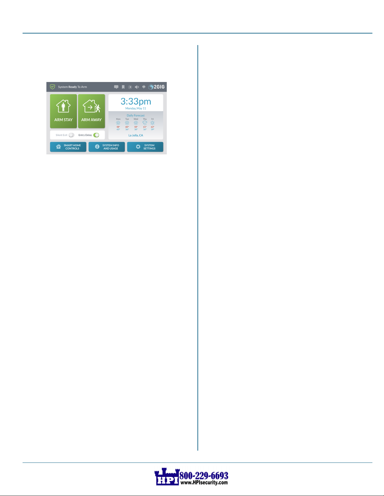
If your Remote Service Provider providesweather forecastsand you have
added thisoption aspart of your service agreement, you can view five-day
weather forecastson the Home screen of the touchscreen display.
Figure 19 Five-Day Weather Forecast
Copyright © 2016 Nortek Security &Control LLC 19
Page 20
3 Touchscreen Basics Proprietary &Confidential
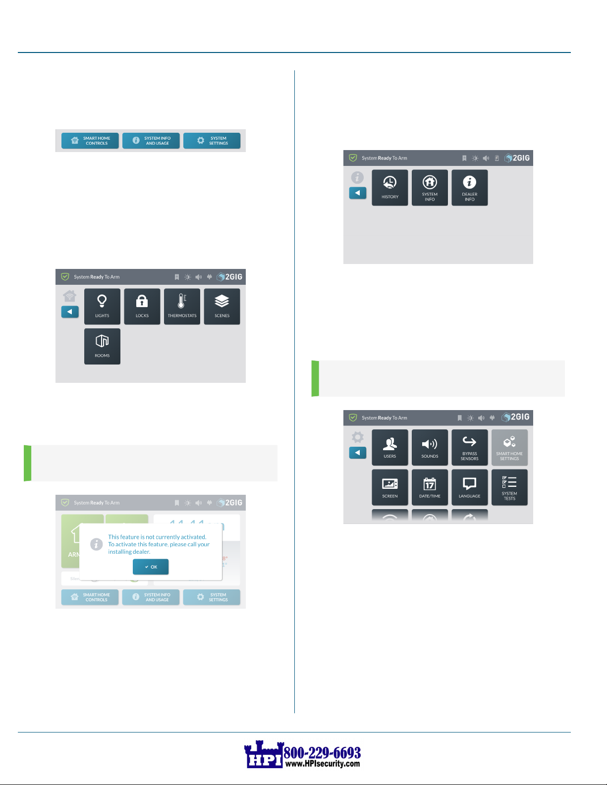
Using the System Menus
Across the bottom of the Home screen, users can tap a button to access
other menus. These menus include Smart Ho me Controls, System
Info an d Usage, and System Settin gs.
Figure 20 System Menus
Smart Home Controls
Tap the Smart Home Co ntrols button on the Home screen to reveal the
Smart Home Controls menu. These options give users the abilityto
operate any smart home devices ( if installed) directlyfrom the GC3 Panel.
To learn about options in thismenu, see "About the Smart Home Controls
Menu" on page 42.
System Info and Usage
Tap the System Info an d Usage button on the Home screen to reveal
the System Info an d Usage menu. This menu providesusers with
accessto system history, system information, and contact information for
your 2GIGalarm dealer. To learn about the optionsin this menu, see
"System Info and Usage" on page 50.
Figure 23 System Info and Usage Menu
System Sett ing s
Tap the System Settin gs button on the Home screen to r eveal the
System Sett ing s menu. This menu givesusers accessto general
settingsfor the GC3 Security & Automation System. To learn about the
options in thismenu, "SystemSettings" on page 53
Figure 21 Smart Home Controls Menu
If the Smart Home Controls menu is not configured on your system, the
following notification message appears when you tap the Smart Home
Con trols button. Tap OK to dismiss the message.
NOTE: Consult your security provider for information about
enabling the Smart Home Controls feature on your system.
Figure 22 Feature Not Currently Activated Message
NOTE: To use this feature, you must know the four-digit
Master User Code.
Figure 24 System SettingsMenu
20 Copyright © 2016 Nortek Security &Control LLC
Page 21
Proprietary &Confidential 3 Touchscreen Basics
Responding to Trouble Alerts
To ensure that allsystem components are operating under optimal
conditions, the system continuallypollsall of the wired and wireless
sensors paired with the system. It also continuously checksthe GC3 Panel
to ensure that it isoperating properly. If a trouble condition is detected, the
system alerts you of the issue.
Monitoring the System for Trouble Conditions
The system monitors the GC3 Panel and its sensors so it can notifyyou
when the following trouble conditions occur:
AC power loss to the panel
Cell radio connection interrupt ion
Sensor low b attery
Panel backup battery low
Sensor tamper
Panel tamper
Sensor supervision (if en abled)
When a Troub le Condition Occurs
When a trouble condition occurs, the system alerts you so that either you
or your 2GIGalarm dealer can promptly address the issue and return the
system to proper working order:
An alert notification issent to the system's Inbox and the
Messages icon flashes.
The system sounds six (6)alert tones every minute, untilthe alert
is acknowledged.
NOTE: Consult your installer to determine if the
Trouble Doesn't Sound at Night feature isenabled
on the system. When enabled, the system silences
only the alert tones only during the nighttime hours.
It will not stop the trouble alert notification from
displaying on the touchscreen so theycan be
acknowledged, nor willit stop the trouble alert report
from being sent to the Central Station.
NOTE: For compliance with UL 985: Household
Fire Warning System Units, the six( 6)trouble alert
tones for WirelessSmoke/Heat/Freeze Alarms and
WirelessCarbon MonoxideDetectors ar e required
to sound at an interval of once every four (4) hours,
until the condition causing the alert isresolved.
A trouble report is sent to the Central Station.
NOTE: Consult your installer to determine if the
Trouble Reports to CSfeature isenabled. When
enabled, the system tr ansmits trouble reports about
sensors to the Central Station.
Copyright © 2016 Nortek Security &Control LLC 21
Page 22

3 Touchscreen Basics Proprietary &Confidential
THIS PAGE INT ENTIONALLY LEFT BLANK
22 Copyright © 2016 Nortek Security &Control LLC
Page 23

4 BURGLARY PROTECTION
This chapter includes the following information:
Overview 24
Important Con cept s 24
Sample Burglary Alarm Plan 25
Arm the System 26
Force Bypassing 27
Use the Quick ExitButto n 28
In t he Event of an Exit Error 29
To Disarm th e System 29
Transmit a User Duress Report 30
In t he Event of a Burglary Alarm 30
Copyright © 2016 Nortek Security &Control LLC 23
Page 24
4 Burglary Protection Proprietary &Confidential
Overview
During setup, the installer typicallyconfigures a variety of wireless and
wired sensors to protect your dwelling from unwanted intrusion. Different
types of sensors may be installed in your dwelling for burglary protection
including door/window contacts,glassbreak detectors, image sensors,
and motion detectors. These sensors are intended to protect both the
perimeter and interior of the premises.
NOTE: This burglary alarm system is in compliance with the
standards defined in UL 681: Installation and Classification of
Burglar and Holdup Alarm Systems and UL 827: CentralStation Alarm Services.
Important Concepts
To help you get the most out of the burglary protection part of the system,
it is useful to understand the concepts detailed below.
Perimeter andInterior Sen sors
The system provides burglary protection using a combination of sensors
that have been installed in and around your dwelling:
Perimeter Sensors: Sensors intended to place the system into
an alarm state when an intruder enters a dwelling. Perimeter
sensors (for example, Door/Window Contacts and Wireless
Glass Break Detectors) are typically installed at possible entry
points, such asfront doors, sliding glass doors, backdoors, side
doors, garage doors, and picture windows.
Interior Sensors: Sensors intended to place the system into an
alarm state by detecting forced entr y of the premises by an
intruder. Interior sensors are typically installed at possible
movement points.For example, a motion detector might be
installed to detect movement across a basement, down a hallway,
or up a stairwell.
Once installed, the system continuously monitors all of its sensors. For an
alarm to sound, burglary protection sensors must be armed (see "Arm the
System" on page 26). The system is also programmed by the installer to
notify you about different events. For example, when you open a
perimeter door, it transmits a statusmessage to the GC3 Panel. The panel
then shows that the door is open and the system announcesthe door's
voice descriptor.
Protect ion Zones
When programmed into the system bythe installer, each sensor is
intended to protect a particular zone. Typical examples of zones that may
be protected bya sensor include, Front Door, BackDoor, Basement
Window, Laundry Room, and so on. During programming, the installer
may also create a voice descriptor for each zone. The GC3 Panel uses the
voice descriptor in two ways:
As a verbal announcement to notify occupants when a perimeter
sensor is open, closed, or when an alarm is set off.
As the displayname of the sensor's zone on the touchscreen.
System" on page 26) and OFF (see "To Disarm the System" on page 29).
This system can be armed in one of two modes:
Stay Mode: Arms the system except interior sensors. Arm the
system in this mode when individuals willbe occupying the
premises. T his arms only the sensor-protected perimeter doors
and windows, leaving interior motion sensors or other interior
doors unarmed. In a home setting, Stay Mode isfr equently used
during the evening hours when occupants do not intend to enter
or exit the dwelling. This letsyou move about without triggering
the burglary alarm. Because all the interior burglary pr otection is
OFF, an alarm would only be triggered ifa sensor-protected
perimeter door or window is opened.
Away Mode: Arms the system including interior sensors. Use
this mode to arm the system when everyone willbe leaving the
premises. T his mode arms all sensor- protected perimeter doors
and windows, interior motion sensors, interior glass break
sensors, and any other sensor-protected interior doors. Away
Mode isfrequently used during day time hour s in residential
installations and during non-businesshours in commercial
installations. Because all burglary protection features are ON, an
alarm would be triggered when movement is detected, if any
protected doors or windows are opened, or if glass breakage is
detected (if glass break detectors have been installed).
Open and Closed Sensors
Before you can arm your system, allprotected doors, windows, and other
protection zonesmust be closed or bypassed (see "Force Bypassing" on
page 27). For example, if you leave a protected window open, the system
considers it an open sensor. If a protected window isshut, the system
considers it a closed sensor.
Bypassed Sensors
When sensors are left open, the system cannot be armed unless that
sensor is closed (see "Open and Closed Sensors" above) or added to the
system's Bypassed Sensors list. Bypassed Sensors are ones that you
intentionally decide to leave unprotected. See "Force Bypassing" on page
27.
NOTE: Bypassed sensors offer no protection and cannot
cause an alarm. Use bypass if you want to arm your system
with one or more sensors open and intentionally
unprotected.
Stay and Away Mode
Unlike fire protection sensors (which ar e alwaysON and protecting the
dwelling), burglary pr otection sensors must be turned ON(see "Arm the
24 Copyright © 2016 Nortek Security &Control LLC
Page 25
CP
ES
DW
PIR
CP - CONTROL PANEL
DW - DOOR/WINDOW SENSOR
PIR - MOTION DETECTOR
GB - GLASS BREAK SENSOR
PAD - WIRELESS KEYPAD
ES - EXTERNAL SIREN
LIVING
DINING
KITCHEN
ENTRY
BATH
DEN
GB
BED
DWDW
DW
DW
DW
DW
DW
DW
FRONT AND SIDE DOOR SENSORS
(WITH ENTRY/EXIT DELAY)
DW
BED
DW
GARAGE
GB
PAD
PIR
DW
DW
DW
MAIN AND SIDE GARAGE DOOR SENSORS
(WITH ENTRY/EXIT DELAY)
diag-gc3-burglary-floor-plan-en
Proprietary &Confidential 4 Burglary Protection
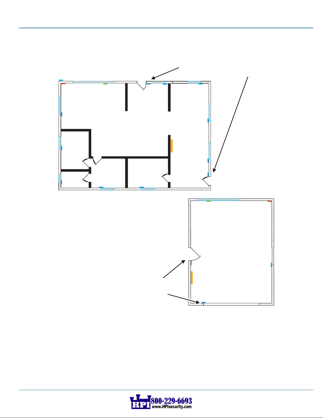
Sample Burglary Alarm Plan
Before the installation, your 2GIG alarm dealer willwork with you to design, install, and configure a system intended to best protect your dwelling. This
illustration isan example of a typicalresidentialburglary alarm system offering both perimeter and interior protection:
Figure 1 Sample Burglary Alarm Plan
Copyright © 2016 Nortek Security &Control LLC 25
Page 26

4 Burglary Protection Proprietary &Confidential
Arm the System
You can arm the system onlywhen the system status message indicates
that it is in the SystemReady to Arm or System Ready to Arm (BYPASS)
state.
IMPORTANT: If any sensors are open (for example, a
perimeter door or window is ajar) the system will be placed
into the System Not Ready to Arm state and revealsthe
unprotected zone in Sensors Not Ready list on the
touchscreen. Before you can ar m the system, you must
either close the open sensor(s) or bypassthe open sensor
(s). See "Force Bypassing" on the facing page.
TIP: If you have purchased a key fob (or multiple fobs) to
control the GC3 Security & Automation System, you can also
arm the system using your key fob. See "Arming the System
Using a Keyfob" on page 40.
Arm the System (Stay Mode)
Stay Mode arms the system except interior sensors. Use this mode when
occupants will be staying on the premises. In residentialinstallations, Stay
Mode isfrequently used during the evening hours when occupants do not
intend to enter or exit the dwelling. T his lets you move about without
triggering the burglary alarm. Because allthe interior burglary protection is
OFF, an alarm would only be triggered ifa sensor-protected perimeter
door or window isopened. To learn how to arm the system in Away Mode,
see "Arm the System (Away Mode)" below.
NOTE: Consult your installer to determine if your system is
configured with the QuickArming feature. When enabled,
the Quick Arming feature allowsanyone to arm the system
without entering a user code. When disabled, you must enter
an active, four-digit user code to arm the system.
To arm the system in Stay Mode:
1. Ensure that allperimeter doors and windows are closed. The
system status message should read System Ready to Arm. If the
status messages reads System Not Ready to Arm and the
Sensors Not Ready list appears, a protected door or window is
open. You must first close that door/window or placeit on the
Bypassed Sensors list. See "Force Bypassing" on the facing
page.
2. At the Home screen, tap Arm Stay.
3. (Optional)At the Enter Your Code to Arm the System
screen, enter an active, four-digit user code. If the Quick Arming
feature is enabled, you willskip this step and not be prompted for
a user code.
An Exit Delay countdown timer appears and the system
announces "Arming Stay." The countdown givesoccupants time
to enter or exit the premisesthrough a protected door.
4. (Optional)I you want to silence the countdown beeps and
announcements, tap Silence. This turns the Silent Exit feature
ON.
Once the countdown expires, occupants willnot be able to enter or exit
through protected doors and windows without tr iggering the burglary
alarm.
Arm the System (Away Mo de)
Away Mode arms the system including interior sensors. Use this mode
when occupantswill be leaving the pr emises. When arming the system in
Away Mode, the system arms all sensor-protected perimeter doors and
windows, interior motion sensors, interior glass break sensors, and any
other sensor-protected interior doors. In residential installations, Away
Mode isfrequently used during daytime hours. In commercialinstallations,
it is mostfrequently used during non-businesshours. Because allburglary
protection features are ON, an alarm would be tr iggered when movement
is detected, if any protected doors or windows ar e opened, or if the system
detects breaking glass (if glassbreak detectors have been installed).
To learn how to arm the system in Stay Mode, see "Arm the System (Stay
Mode)" above.
NOTE: Consult your installer to determine if your system is
configured with the QuickArming feature. When enabled,
the Quick Arming feature allowsanyone to arm the system
without entering a user code. When disabled, you must enter
an active, four-digit user code to arm the system.
To arm the system in Away Mode:
1. Ensure that allperimeter doors and windows are closed. The
system status message should read System Ready to Arm. If the
status messages reads System Not Ready to Arm and the
Sensors Not Ready list appears, a protected door or window is
open. You must first close that door/window or placeit on the
Bypassed Sensors list. See "Force Bypassing" on the facing
page.
2. At the Home screen, tap Arm Away.
3. (Optional)At the Enter Your Code to Arm the System
screen, enter an active, four-digit user code. If the Quick Arming
feature is enabled, you willskip this step and not be prompted for
a user code.
An Exit Delay countdown timer appears and the system
announces "Arming Stay." The countdown givesoccupants time
to enter or exit the premisesthrough a protected door.
NOTE: Consult your installer to determine how the
ExitDelay feature is configured on your system (45120 seconds).For compliance with ANSI/SIA CP-
01-2010, the Exit Delay feature is configured to 45
seconds by default.
NOTE: Consult your installer to determine if the Exit
Delay Restart feature isenabledon your system.
This feature restarts the Exit Delay countdown if an
occupant enters or exitsthrough a protected door or
window before the countdown expires. For
compliance with ANSI/SIA CP-01-2010, thisfeature
must be enabled.
26 Copyright © 2016 Nortek Security &Control LLC
Page 27
Proprietary &Confidential 4 Burglary Protection
2. (Optional)If you want to silence the countdown beeps and
announcements, tap Silence. This turns the Silent Exit feature
ON and extends the Exit Delaycountdown.
NOTE: Consult your installer to determine how the
ExitDelay feature is configured on your system (45120 seconds).For compliance with ANSI/SIA CP01-2010, the Exit Delay feature is configured to 45
seconds by default.
NOTE: If you want to cancel the arming action
before the countdown expires, tap Disarm. Then
enter an active, four-digit user code.
NOTE: Consult your installer to determine in the
Auto Stayfeature is enabled on your system. If you
arm the system in Away Mode and no one exits
through an Exit Delaydoor before the countdown
expires, the system will automatically arm itself in
Stay Mode.
During the Exit Delay countdown, the system emitsa seriesof beeps that
become faster dur ing the last 10 seconds. Once the countdown expires,
occupants will not be able to enter or exitthrough protected doors and
windows without triggering the bur glary alarm.
Force Bypassing
When a protected door or window is open, the system places the sensor
on itsSen sors Not Ready list.In order to arm the system, you must
either close the sensor or placeit on the system's Bypassed Sensors list.
Bypassed Sensors are ones that you intentionally decide to leave
unprotected. This method of bypassing a sensor is called Force
Bypassing. To learn how to manually bypass a sensor, see "Manually
Bypassing a Sensor" on page 59.
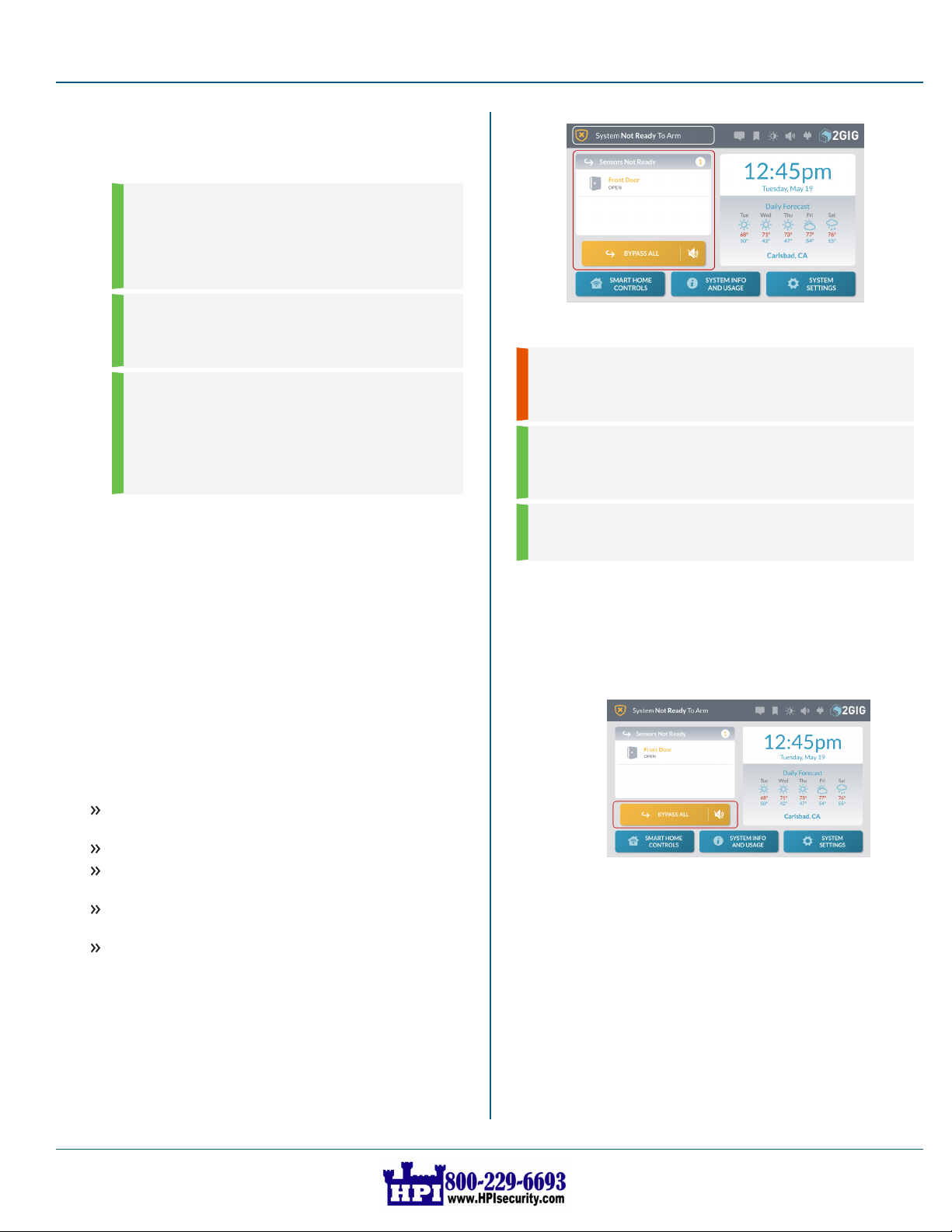
Openin g a Senso r When t he System is Disarmed
When a protected door or window is opened while the system isdisarmed,
the GC3 Panel responds as follows:
The system statusmessage on the touchscreen r eads System
Not Ready to Arm.
The Sensors Not Ready list and Bypass All button appears.
The name of the protected zone appears on the Sensors Not
Ready list.
The number of open sensors appears in the top-right corner of
the list.
The system usesthe voice descriptor assigned to the sensor to
announce that the protected zone is open.
Figure 2 System Not Ready to Arm—Sensors Not Ready List
WARNING!! A bypassed burglary protection sensor does
NOTprovide security pr otection when the system is armed.
See "Bypass Sensors" on page 59.
NOTE: Residentialalarm systems do not permit you to
bypasssensors installed in fire, carbon monoxide, or
emergencyzones.
NOTE: In order to bypass a sensor, you must know the
Master User Code.
Force Bypassing a Sensor
If youwant to arm the system and ignore the open sensor, you must
bypassthe sensor. This is called "force" bypassing a sensor.
To force bypass the sensor:
1. Below the Sensors Not Ready list, tap Bypass All.
Figure 3 Sensors Not Ready >Bypass All
2. At the Enter your code to bypass sensors screen, enter an
active, four-digit user code.
Copyright © 2016 Nortek Security &Control LLC 27
Page 28

4 Burglary Protection Proprietary &Confidential
Figure 4 Enter the Master Code to Bypass Sensors
3. When the system status message changesto System Ready to
Arm (BYPASS), you can arm the system. See "Arm the System"
on page 26.
Figure 5 System Ready to Arm (BYPASS)
Figure 6 Bypassed Sensors List
Canceling a Bypassed Senso r
To remove a sensor from the Bypassed Sensor list:
1. Tap the circle indicator showing how many devices are currently
bypassed.
Figure 7 Bypassed Sensors Indicator
Figure 9 Enter Your Code to Cancel Bypass
This changes the system's status backto System Not Ready to
Arm and movesthe sensor to the Sensors Not Ready list.
Figure 10 System Not Ready to Arm—Sensors Not Ready List
Use the Quick ExitButton
The Quick Exit button givesusers the ability to start an Exit Delay
countdown while the system isarmed. This gives users the abilityto leave
the premisesthrough an Exit/Entry door, instead of having to disarm and
then rearm the system. When the Allow Quick Exit setting is enabled, the
Quick Exit button appears on the SystemArmed (STAY) screen.
NOTE: Consult your installer to determine if the Allow Quick
Exitsetting is enabled or disabled on the system.
2. Below the Bypassed Sensors list, tap Cancel Bypass.
Figure 8 Bypassed Sensors >Cancel Bypass Button
3. At the Enter your code to cancel bypass screen, enter an
active, four-digit user code.
28 Copyright © 2016 Nortek Security &Control LLC
To use the Quick Exit button:
1. Arm the system in Stay Mode or Away Mode. See "Arm the
System" on page 26.
2. At the System Armed ( STAY) screen, tap Quick Exit.
Figure 11 System Armed—QuickExit Button
Page 29
Proprietary &Confidential 4 Burglary Protection
This starts the Exit Delay countdown to give you time to exit through an
Exit/Entry door without having to re-arm the system. Atthe end of the
countdown, the system arms itself in the appropriate mode.
In the Event of an Exit Error
If youarm the system and an Exit/Entry door is left in a violated state or
condition at the time the Exit Delaycountdown expires (for example, the
door you exit from doesn't close behind you), the GC3 Panel sounds the
localalarm and the Entry Delaycountdown begins. If you do not disarm
the system when the Entry Delay countdown begins, the system
automaticallybegins the alarm transmission sequence. The panel also
transmits an Exit Error report to the Central Station and displaysan Exit
Error message on the panel screen, as shown below.
Figure 12 Alarm Transmission &Exit Error Sequence
To Disarm the System
To turn the system's burglary protection sensors OFF, you disarm the
system. Disarming the system also silencesany type of alarm that might be
sounding.
NOTE: To use this feature, you must have an active,four-
digit user code. See your system's Master User to obtain a
code.
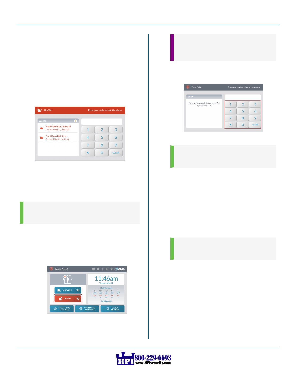
Disarm the System (Stay Mode)
When the system is armed in Stay Mode, any person with an active, fourdigit user code can disarm the system.
To disarm the system:
1. At the SystemArmed screen, tap Disarm.
TIP: If you want to exit the premises through one of
the Exit/Entry doors while the system isarmed in
Stay Mode, tap the Quick Exit button .See "Use
the Quick ExitButton" on the previous page.
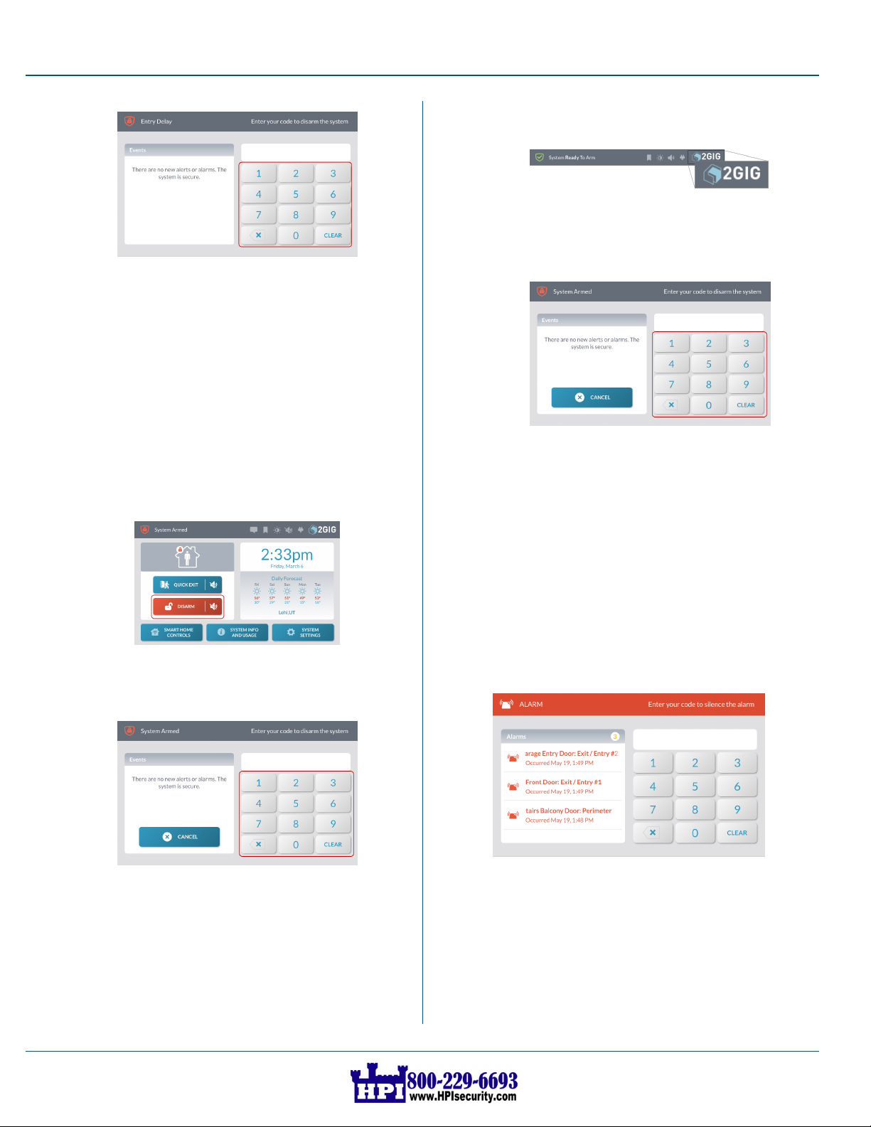
2. At the Enter your code to disarm the system screen, enter
an active, four-digit user code. You must enter a code before the
Entry Delaycountdown expires.
Figure 14 Enter Your Code to Disarm the System
NOTE: Consult your installer to determine how the
Entry Delayfeature is configured on your system
(30-240 seconds).
The system isdisarmed. If protected doors and windows are closed, the
system sounds the System Disarmed, Ready to Armannouncement. If
protected doors or windows are open, the system sounds the System
Disarmed Not Ready to Arm announcement.
Disarm the System (Away Mode)
When the system is armed in Away Mode, anyperson with an active, four digit user code can disarm the system. You must enter the code before the
Entry Delaycountdown expires to avoid setting off the alarm.
To disarm the system fr om Away Mode:
1. Enter the premisesusing one of the Exit/Entry doors. The
system's Entry Delay beeps sound.
NOTE: Consult your installer to determine how the
Entry Delayfeature is configured on your system
(30-240 seconds).
2. At the Entry Delay screen, enter an active, four-digit user code.
You must enter your code before the Entry Delay countdown
expires.
Figure 13 System Armed >Disarm Button
Copyright © 2016 Nortek Security &Control LLC 29
Page 30
4 Burglary Protection Proprietary &Confidential
1. At the Home screen or from one of the menus, tap the system
logo.
Figure 18 System Logo
2. At the Enter your code to disarm the system screen, enter
the four-digit Duress Code.
Figure 15 Enter Your Code to Disarm the System
The system isdisarmed. If protected doors and windows are closed, the
system sounds the System Disarmed, Ready to Armannouncement. If
protected doors or windows are open, the system sounds the System
Disarmed Not Ready to Arm announcement.
Transmit a User Duress Report
You can enter the Duress Code to transmit a user duress r eport to the
Central Station without alerting an intruder that you are calling for help.
Transmitting a User Duress Report when t he System is Armed
To transmit a user duress report when the system is armed:
1. At the System Armed screen, tap Disarm.
Figure 16 System Armed—Disarm Button
2. Enter the four-digit Duress Code.
Figure 19 Enter the Duress Code
The system willannounce "System Disarmed" and return to the
Home screen.
In the Event of a Burglary Alarm
If one or more armed sensors are tripped whilethe system is armed in
Stay or Away Mode, an alarm condition willoccur and the system's alarm
siren willsound.
If an Entry Delay sensor istripped while the system isarmed in Stay or
Away Mode, the Entry Delay countdown starts to give you time to disarm
the system. If the system isnot disarmed before the countdown expires,
an alarm condition occurs and the system'salarm siren willsound.
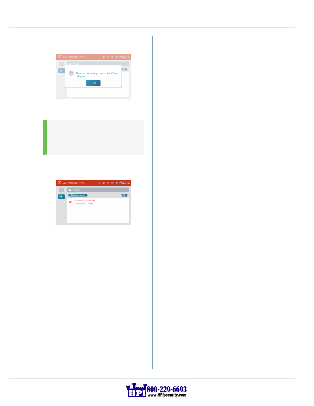
If more than one armed sensor istripped, the system displays the
triggered sensors in chronological or der.
Figure 17 Enter the Duress Code
The system disarms and transmits a silent duress report to the
Remote Service Provider.
Transmitting a Duress Signal when the System is Disarmed
To transmit a user duress report when the system is disarmed:
30 Copyright © 2016 Nortek Security &Control LLC
Figure 20 Alarms Screen—MultipleAlarms in ChronologicalOrder
Silencing the Alarm Sounder (for False Alarms)
If the system is inan active alarm state, anyperson with an active, four digit user code can silence the sounder by disarming the system.
Page 31

Proprietary &Confidential 4 Burglary Protection
If you disarm th e system BEFOREthe Abort Windo w
Dialer Delay countdown expires, the system cancels the
alarm and stops the alarm report from being transmitted to the
CentralStation.
If you disarm th e system AFTERt he Abo rt Window Dialer
Delay countdown expires, the system silencesthe alarm and
transmits an alarm cancellation report to the Central Station.
NOTE: Consult your installer to determine how the Alarm
Abort Window Dialer Delay feature isconfigured on your
system (15-45 seconds). Thissetting specifies the number of
seconds end users have to manually abort the alarm, in the
event of a false alarm. For ANSI/SIA CP-01-2010
compliance, the default setting is30 seconds. For UL 1023:
Household Burglar Alarm Units compliance, this setting may
be configured to a maximum of 45 seconds.
To silence the alarm sounder:
1. When an Alarm is sounding, enter an active, four-digit user code.
3. Tap OK to dismiss the notification message.
Clearing an Alarm
If an alarm occurs while you are away, the GC3 Panel'sPiezo Sounder will
sound for a preset amount of time (as defined by the Burglary Bell Cutoff
Time and/or the Fire Bell Cutoff Time). Upon entering the premises, the
system emits fast, repeated beeps to warn you that an alarm was set off
while you were away.
Figure 23 Alarm Report Already Transmitted…Cancel
Being Sent Message
NOTE: Consult your installer to determine how the Burglary
BellCutoff Time and Fire Bell Cutoff Time is configured on
your system. The time can be configured to last 4 minutes, 8
minutes, 12 minutes, 16 minutes, or Unlimited (no cutoff).
The default setting for both featur es is four (4) minutes.
Figure 21 Enter Your code to Silence the Alarm Screen
2. Depending on how quicklyyou enter your code, one of the
following occurs:
a. If you enter your code before the Abort Window Dialer
Delay countdown expires, the following message
appears.
Figure 22 Disarming Canceled an Alarm Before it was
Transmitted Message
b. If you enter your code after the Abort Window Dialer
Delay countdown expires and before the Alarm Cancel
Time expires, the following message appears.
CAUTION! If the system emits fast, repeated beeps (instead
of the typicalEntry Delay beeps), proceed indoors with
extreme caution. For your safety, itis recommended that you
immediatelyleave the premises, go to a secure location, and
then contactyour localauthorities for assistance. If you have
any reason to believe an intruder is pr esent, do NOTenter
the premisesuntil the dwelling is deemed safe by local
authorities.
To clear an alarm:
1. At the Alarm screen (after the Burglary Bell Cutoff Time or Fire
BellCutoff Time expires), enter an active, four -digit user code.
Figure 24 Enter Your Code to Clear the Alarm
2. Depending on how quicklyyou enter your code, one of the
following occurs:
Copyright © 2016 Nortek Security &Control LLC 31
Page 32
4 Burglary Protection Proprietary &Confidential
a. If you enter your code before the Alarm Cancel T ime
countdown expires, the following message appears.
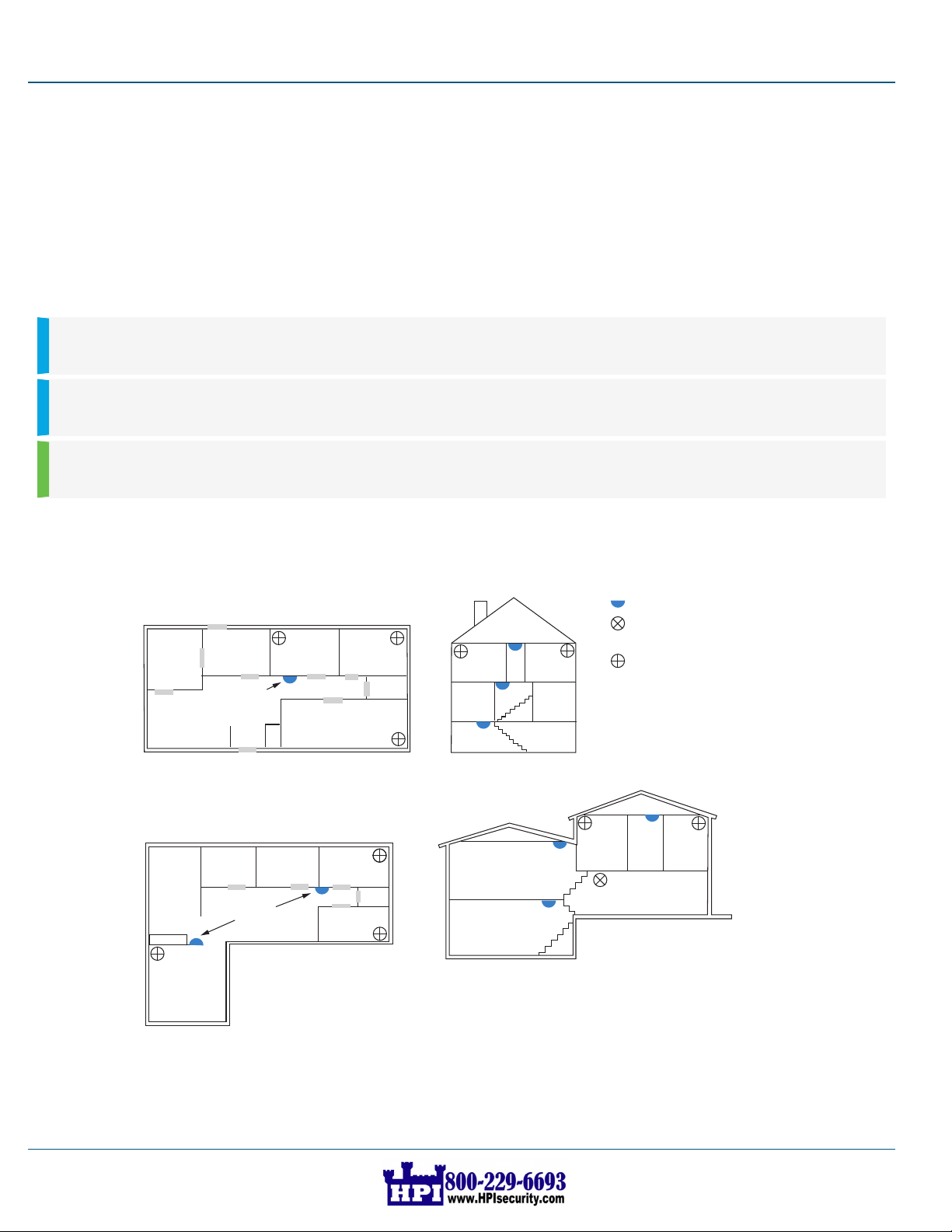
Figure 25 Alarm Report Already Transmitted…Cancel
Being Sent Message
b.
NOTE: Consult your installer to determine
how the Alarm Cancel T ime setting is
configured on your system. For compliance
withANSI/SIA CP-01-2010, the factory
default setting is five ( 5)minutes.
c. If youenter your code after the Alarm Cancel Time
countdown expires, the system reveals the Alarm
Histo ry.
Figure 26 Alarm History
The system clears the alarm. You can also clear the Alarm
History. See "Clear the Alarm History" on page 36.
32 Copyright © 2016 Nortek Security &Control LLC
Page 33

5 FIRE &CARBON MONOXIDE PROTECTION
This chapter includes the following information:
Overview 34
Important Con cept s 34
Natio nal Fire Alarm and Signaling Code 34
Recommended Smoke Alarm Placement 34
Emergency Action Plan 35
In t he Event of a Fire Alarm 35
Silence aFalse Fire Alarm 35
In t he Event of a Carbon Monoxide Alarm 35
Clear the Alarm Histo ry 36
Copyright © 2016 Nortek Security &Control LLC 33
Page 34
DINING KITCHEN BEDROOM
BEDROOM
BEDROOM
LIVING
ROOM
SMOKE
ALARM
A smoke alarm should be located between the sleeping
area and the rest of the family living unit.
BEDROOM
BEDROOM
BEDROOM
TV
ROOM
DINING KITCHEN
SMOKE
ALARMS
LIVING
ROOM
In family living units with more than one (1) sleeping
area, a smoke alarm should be provided to protect
each sleeping area.
Indicates a required smoke alarm
Indicates an optional smoke alarm
if door is not provided between
living and recreation rooms
Indicates additional smoke alarms
required for new construction
BED
ROOM
BED
ROOM
LIVING
ROOM
HALL
BASEMENT
DINING
ROOM
A smoke alarm should be
located on each story.
IMPORTANT: Regulations pertaining to smoke alarm installations vary. For more information, contact your local fire
department or local authority having jurisdiction.
LIVING
ROOM
BASEMENT
BED
ROOM
HALL
BED
ROOM
RECREATION ROOM
A
B
C
D
In split-level configurations, smoke
alarms are optional where a door is
not provided between a living and
recreation room.
5 Fire &Carbon Monoxide Protection Proprietary &Confidential
Overview
During setup, a professional installer typicallyconfigures a variety of wireless and wired sensors to provide the dwelling with continuous, 24-hour-a-day, heat,
smoke, and gas protection. Most systems ar e installed with both Wireless Smoke/Heat/Freeze Alarms and WirelessCarbon MonoxideDetectors.
Important Concepts
To help you get the most out of your fire, heat, and gas protection system, it isuseful to understand these concepts.
National Fire Alarm and Signaling Code
IN THE UNITED STAT ES, CANADA, AND OTHERCOUNTRIESREQUIRED T O MEET THIS STANDARD: T HISEQUIPMENT MUST BE
INSTALLED IN ACCORDANCE WITH CHAPTER 2 of ANSI/NFPA 72: National Fire Alarm and Signaling Code (National Fire Protection
Association, Batterymarch Park, Quin cy, MA 02269).
IMPORTANT: This system ships with an approved 24-hour backup battery installed and is compliant with UL 985: Household F ire Warning
System Units.
IMPORTANT: Specificrequirements forHeat and Smoke Alarms vary from state to state and from region to region. A pr ofessionalinstaller must
always verify current requirements for your area with the localFire Department.
NOTE: Instructions describing the proper installation, operation, testing, maintenance, evacuation planning, and repair service ar e provided in
the printed Installation Instructions included with all 2GIGWirelessSmoke/Heat/Freeze Alarms and WirelessCarbon MonoxideDetectors.
Recommended Smoke Alarm Placement
Early warning fire detection is best achieved when fire detection equipment is installed in allr ooms and ar eas of the premises. Equipment should be installed as
follows:
Figure 1 Recommended Smoke Alarm Placement
34 Copyright © 2016 Nortek Security &Control LLC
Page 35

Proprietary &Confidential 5 Fire &Carbon Monoxide Protection
Emergency Action Plan
Establish and regularly practicea plan of escape with allmembers of your
household in the event of fire. The NationalFire Protection Association
recommends the following steps:
1. Mount your detector or your interior or exterior alarm sounders
where they can be heard by all occupants.
2. Determine two means of escape from each room. One path of
escape should lead to the door that permits normal exit from the
building. The other should be an alternate escape, such asa
window, should the path to the escape door be impassable.
Station an escape ladder at such windows if there isa long drop to
the ground.
3. Sketch a floor plan of the building. Show windows, doors, stairs,
and rooftops that can be used to escape. Indicate escape routes
for each room. Keep theseroutes free from obstructionsand post
copiesof the escape routes in every room.
4. Ensure that allbedroom doors are shut while you are asleep,
preventing deadlysmoke from entering whileyou escape.
5. Touch the door before opening it. If the door is hot, checkyour
alternate escape route. If the door is cool, open it cautiously. Be
prepared to slam the door shut if smokeor heat rushes in.
6. When smoke ispr esent, crawl on the ground. Do not walk
upright, since smoke risesand may overcome you. Air is typically
clearest near the floor.
7. Escape quickly, but don’t panic.
8. Establish a place outdoors, away fr om your house, wher e
everyone can meet and then take steps to contact the authorities
and account for those missing. Ensure that nobody returns to the
premises.
In the Event of a Fire Alarm
Smoke and Carbon Monoxide (CO) detectors may be installed to protect
the occupants of the dwelling from the har mful, and possiblydeadly effects
of smoke, heat, and fire-related dangers. The system's fire and
emergencyprotection features are alwaysprotecting the premises.
NOTE: A professional installer must ensure that all
Smoke/Heat Alarms are installed in compliance with all
national, regional, and local laws, statutes, and guidelines.
Silence aFalse Fire Alarm
In the event of a false fire alarm (for example, bur ning food or another
non-emergency condition), you can silence the alarm.
To silence the alarm:
1. Enter an active, four -digit user code to silence the alarm.
IMPORTANT: Consult your installer to determine
how the Abort Window Dialer Delay is configured on
your system. This defines the amount of time the
system willwait to initiate the digital dialer when an
alarm condition istr iggered and specifies the
number of seconds you have to manually abort the
alarm, before an alarm repor t issent to the Central
Station.
IMPORTANT: Consult your installer to determine
how the Alarm Cancel T ime is configured on your
system. This defines the amount of time you have to
send an alarm cancellation report to the Central
Station. expires. The factory default setting for the
system isfive (5) minutes.
2. Review the Alarms screen to deter mine which sensor activated
the alarm.
NOTE: If the alarm restarts, smoke may be present
in the alarm's detection chamber. Enter the user
code again. T hen fan the detection chamber on the
sensor for 30 seconds.
3. After the problem hasbeen addressed, tap the Clear Alarm
Histo ry button.
4.
NOTE: For Smoke/Heat Alarms and CO Detectors,
the Clear Alarm History button will not permit you
to clear any history untilthe GC3 Panel receivesa
message from the sensor that it has returned to
normal operations.
In the Event of a Carbon Monoxide Alarm
Detectors may have been installed to safeguard the occupants of your
dwelling from the dangerous and possibly deadly effectsof CO gas . See
"Safety Precautionsand Notations" on page 6.
If a CO alarm isactivated, the system emitsa warning siren untilthe
system no longer detects COin the environment.
To respond to a COalarm event:
1. Gather alloccupants and immediatelymove to fresh air (either go
outdoors or stand by an open door/window).
DANGER!!! To protect yourself and others from
injury and/or death, do not re-enter the home or
move away from the open door/window untilthe
premises has been approved for safe reentry by
emergencyofficials. T o learn about other ways to
safeguard your home fr om the harmful effects of
CO, refer to the guidelines defined by your local,
state, or regional officials.
2. Dial9-1-1 (or your region's emergency services number) to
report the situation to authorities.Always call from safe location.
3. Surveyeach person's health, checking for flu-like symptoms and
other evidence of COpoisoning.
4.
TIP: To prevent a future occurrence, contact an
Copyright © 2016 Nortek Security &Control LLC 35
Page 36
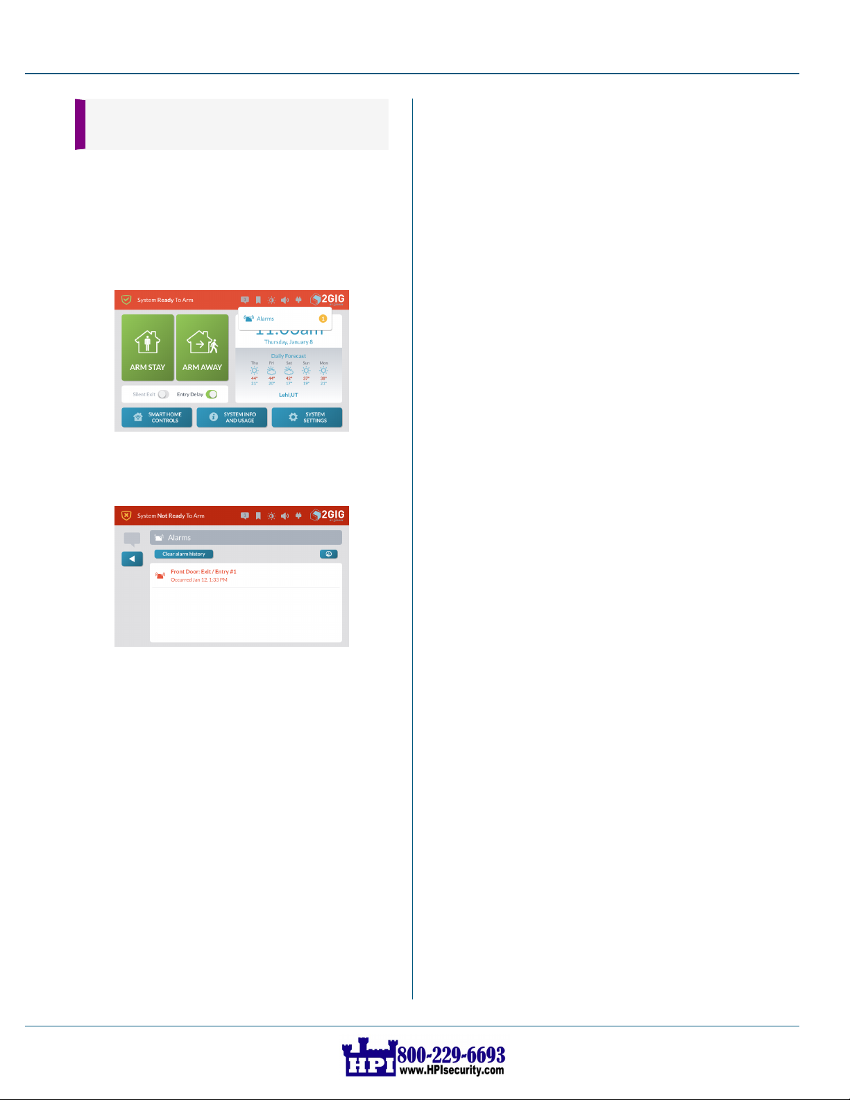
5 Fire &Carbon Monoxide Protection Proprietary &Confidential
industry professionalto evaluate allpossible sources
of COgas in the dwelling.
Clear the Alarm History
After an alarm is activated on the system whileyou are way, a notification
message appears inthe Alarm History.
To clear the alarm history:
1. Tap the Message system icon . Then tap Alarms.
Figure 4 New Alarms
2. Review the Alarms list.Then tap Clear Alarm History.
Figure 5 Alarms Screen
36 Copyright © 2016 Nortek Security &Control LLC
Page 37

6 EMERGENCY FEATURES
This chapter includes the following information:
24-Ho ur Alarm Buttons 38
Activate a Manual Panic,Fire, or Emergency Alarm 38
Copyright © 2016 Nortek Security &Control LLC 37
Page 38
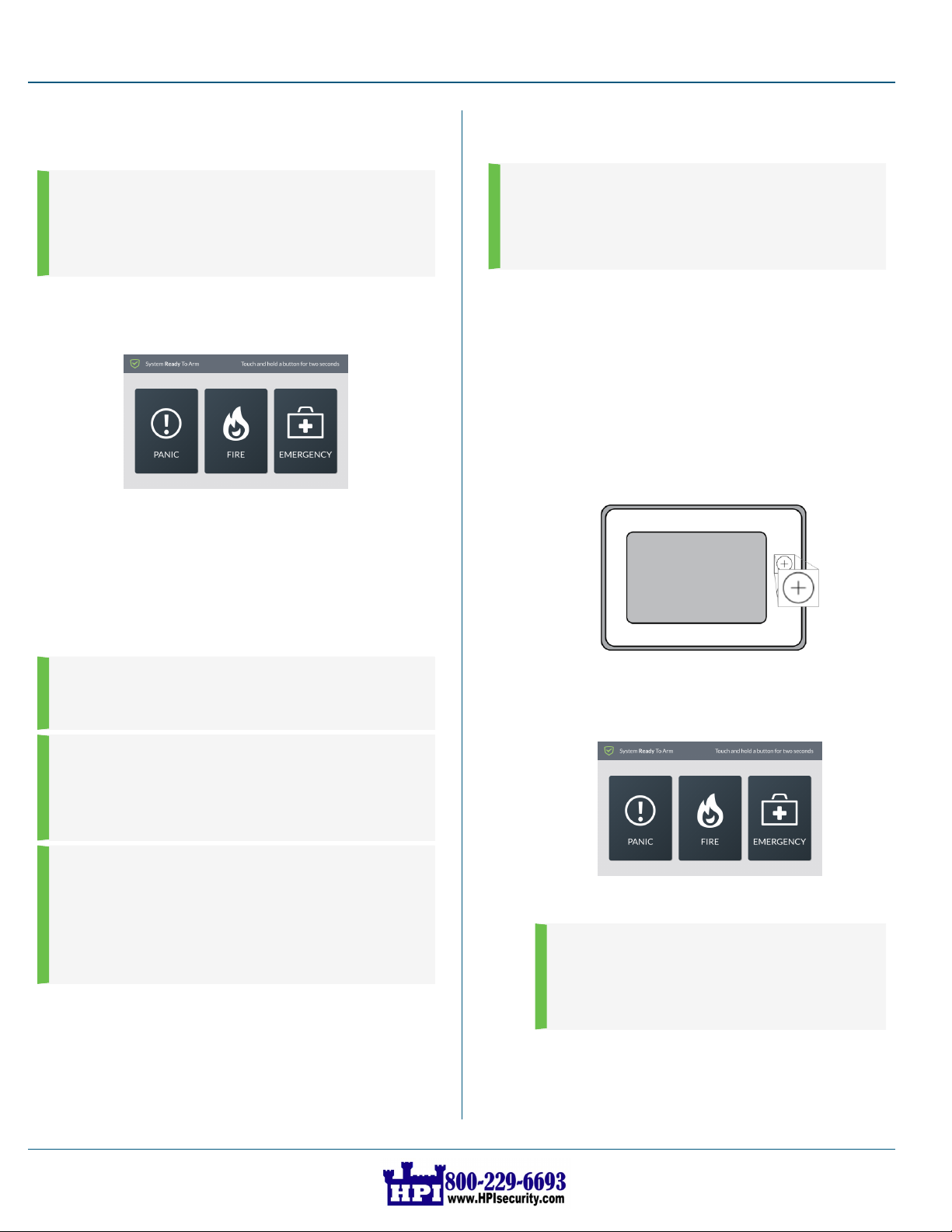
6 Emergency F eatures Proprietary &Confidential
24-Hour Alarm Buttons
Three 24-hour alarm buttons can be shown or hidden bythe installer on
the Control Panel'stouchscreen: Panic, Fire, andEmergency.
NOTE: Consult your installer to show or hide the 24-Hour
Emergency Alarm Buttons on your system. Typically, allof
these buttons are configured to display on the touchscreen
default. However, some systems are not configure to reveal
all of the buttons.
You can open the following screen by pressingthe Alarm button on the
Control Panel. See "Activate a Manual Panic,Fire, or Emergency Alarm"
below. This revealsa screen that is typically configured by installers to
include these 24-hour emergency alarm buttons:
Figure 1 24-Hour Alarm Buttons
Panic Button
When a user touches and holds the Panic button for two (2)seconds, the
system immediatelygoes into the alarm state. Depending on how the
system isconfigured, the Control Panel emits a loud, patterned warning
siren or setsoff a silent panic alarm with no siren. The system also
transmits a police report to the Central Station.
disarmed (see "To Disarm the System" on page 29) or the Fire Bell Cutoff
Time expires. The system also transmits a Fire Report to the Central
Station.
NOTE: Consult your installer to determine how the Fire Bell
Cutoff Time isconfigured on your system. The time can be
configured to last 4 minutes, 8 minutes, 12 minutes, 16
minutes, or Unlimited (no cutoff). The default setting is four
(4) minutes.
Emergency Button
When a user touches and holds the Emergency button two (2)seconds,
the system immediately goes into the alarm state. The Control Panel emits
a loud , patterned warning siren and continues to sound untilthe system is
disarmed (see "To Disarm the System" on page 29). The system also
transmits an Emergency Report to the Central Station.
Activate a Manual Panic,Fire, or Emergency Alarm
You can activate a panic, fire, or emergency alarm using the GC3 Panel.
To activate a manual alarm:
1. Pressthe Alarm button on the GC3 Panel.
NOTE: Consult your installer to determine if the Police
Emergency Keyis configured to sound an audible alarm or a
silent panicalarm.
NOTE: Consult your installer to determine if the 2-Way Voice
feature is enabled on the system. If enabled, settingoff the
Panic alarm givesoperators at the Central Station the ability
use the Control Panel's built-in speaker and microphone to
converse with people on the premises.
NOTE: Consult your installer to determine if the Silent
Panic/Burglary Listen Only feature isenabled on the system.
If enabled, setting off the Panic alarm givesoperators at the
Central Station the abilityto use the Control Panel's built-in
microphone to listen. If the panic alarm is sent, the operator
can onlylisten. For your protection, you and the operator will
not be able to talk.
Fire Button
When a user touches and holds the Fire button for two (2)seconds, the
system immediatelygoes into the alarm state. The Control Panel emitsa
loud, patterned warning siren that isin compliance with ANSIS3.41
Tempor al-3 Fire Alarm Signal and continues to sound untilthe system is
Figure 2 GC3 Panel—Alarm Button
2. Touch and holdthe Panic, Fire, or Emergency button for two
(2)seconds.
Figure 3 24-Hour Alarm Buttons
3.
NOTE: Consult your installer about your system's
emergencykey settings. Typically, allthree buttons
are enabled and visible on the touchscreen by
default. However, some systems may be configured
to hide one or more of these buttons.
38 Copyright © 2016 Nortek Security &Control LLC
Page 39

7 REMOTE CONTROL
This chapter includes the following information:
Remote Con trol Devices 40
Operate the System with a Key Fob 40
Copyright © 2016 Nortek Security &Control LLC 39
Page 40
7 Remote Control Proprietary &Confidential
Remote Control Devices
The installer can pair your system with one or more wireless key fobs to
give you the ability to arm/disarm your system away from, but within range
of, the control panel using the key fob'sbuttons. The GC3 Security &
Automation System can be paired to work with a maximum of 32 wireless
key fobs. Depending on your individual needs, key fobs can also be
configured by the installer to activate specificalarms.
Operate the System with a Key Fob
The installer can configure each key fob to let you perform up to five (5)
remote functions:
Arm the System in Stay Mode
Arm the System in Away Mode
Disarm the System
Activate an Auxiliary Fun ctio n
Activate an Alarm
NOTE: Consult your installer to determine how your keyfob
is configured to work with the system. Depending on your key
fob's setting, it may or may not be configured to disarm the
system.
Arming the System Usin g a Keyfob
You can arm the system in Stay or Away mode using a key fob that has
been paired with the system.
To arm the system in Stay Mode, press the Stay button on
the keyfob for two (2)seconds.
To arm the system in Away Mode, press the Away button on
the keyfob for two (2)seconds.
external siren/sounder, control a lock, control a light, or used
to activate a different auxiliary function.
Activating an Alarm Using a Key Fo b
To activate an emergency alarm, pressand hold both the Away and
Disarm buttons on the keyfob for five (5)seconds.
NOTE: Consult your installer to determine what type of
alarm your keyfob is configured to activate. Depending on
the individualkey fob settings, this function might be disabled
on your key fob, or it might be configured to activate an
auxiliary, audible, or silent panic alarm.
NOTE: In order to cancel an emergency alarm activated with
a key fob, you must disarm the system at the GC3 Panel.
Alarms cannot be canceled or silenced using a keyfob.
NOTE: Depending on setup options, if any perimeter doors
or windows are open, the system may not allow arming to
Away mode with a wirelesskey fob. Consult your installer to
determine how thisoption is configured on your system.
Disarming the System Using a Key Fob
To disarm the system, press and hold the Disarm button on the key fob for
two (2)seconds.
NOTE: Consult your installer to determine how your keyfob
is configured to work with the system. Depending on the
individual key fob settings, it may or may not be configured to
disarm the system.
Activating an Au xiliary F un ctio n
To activate an auxiliary function, press and hold the Auxiliary button on
the keyfob for two (2)seconds.
NOTE: Consult your installer to determine how your keyfob
is configured to work with the system. Depending on the
individual key fob settings, it may be configured to set of an
40 Copyright © 2016 Nortek Security &Control LLC
Page 41

8 SMART HOME CONTROLS
This chapter includes the following information:
Abo ut th e Smart Home Co ntrols Menu 42
Navigate t o the Smart Home Controls Men u 42
Lights 42
Locks 42
Thermostats 42
Scenes 43
Add a NewRoom 45
Copyright © 2016 Nortek Security &Control LLC 41
Page 42

8 Smart Home Controls Proprietary &Confidential
About the Smart Home Controls Menu
The Smart Home Controls menu givesusers the abilityto control ZWave smart home devices at the GC3 Panel. The system supports a
maximum of 232 Z-Wave devices.
Navigate to the Smart Home Controls Menu
To navigate to the Smart Home Co nt rols menu:
1. At the Home screen, tap Smart Home Controls.
Figure 3 LightsScreen
Locks
Use the controlsin the Locks screen to lock and unlock your smart home
devices.
To lockand unlock devices:
1. Navigate to the Smart Home Controls menu. See "Navigate to
the Smart Home Controls Menu" above.
Figure 1 Home >Smart Home Controls
This r eveals the Smart Home Controls menu.
2. Tap Locks .
3. At the Locks screen, swipe left to unlockor right to lock. You can
also tap the lock or unlock icon.
Figure 2 Smart Home Controls Menu
Lights
Use the controlsin the Lights screen to adjust your smart home lighting
devices.
Dim or Bright en Lights
To dim or brighten lights:
1. Navigate to the Smart Home Controls menu. See "Navigate to
the Smart Home Controls Menu" above.
2. Tap Lights.
3. At the Lights screen, swipe left to dim the light or right to
brighten. You can also tap the dim or brighten icon.
Thermostats
Use the controlsin the Thermostat s screen to operate your thermostats.
To operate the thermostat:
1. Navigate to the Smart Home Controls menu. See "Navigate to
the Smart Home Controls Menu" above.
2. Tap Thermostats.
3. At the Thermostats screen, you have these options:
Figure 4 Thermostats Screen
To chan ge the temperature set points, press the
top arrow to raise the temperature or press the bottom
arrow to lower the temperature.
42 Copyright © 2016 Nortek Security &Control LLC
Page 43
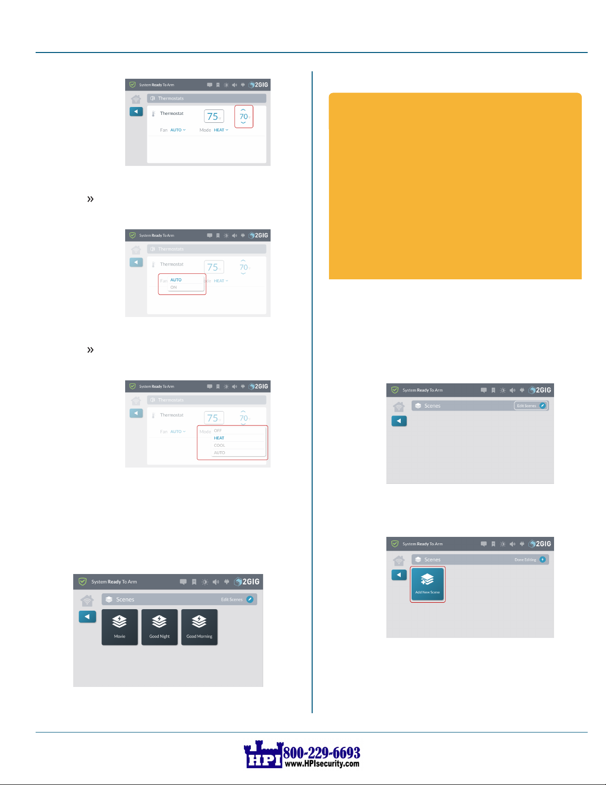
Proprietary &Confidential 8 Smart Home Controls
Figure 8 Smart Home Controls >Scenes
E x a m p l e s : W h e n t o C r e a t e
S c e n e s
There are a wide variety of scenesthat you can create.Some of
the more common include:
Leaving for the Day: Create a scene named "Leave" to lock
Figure 5 Temperature Set Point
the door, turn off all lights, adjust the thermostat.
To chan ge the fan setting, tap the current setting to
open a menu and tap the desired option.
Figure 6 Fan Setting
To chan ge the thermostat mode, tap the current
setting to open a menu and tap the desired mode.
Figure 7 Thermostat Mode
Scenes
Use the Scenes screen to create scenarios that define simple rules for
how your Z-Wave home automation devices work together. There is no
functional limit on the number of scenes that youcan create to control
lights,home automation devices, and other alarm sensors.
Retire for the Nigh t: Create a scene name "Good Night"to
switch OFFthe downstairs lights, lock the entry doors, illuminate
a nightlight in the dwelling's hallways, and adjust the thermostat
setting.
Wake Up in the Morning: Create a scene named "Good
Morning"to adjust the thermostat temperatur e, turn on family
room lights,and turn on the coffee pot.
Add a New Scene
To add a new scene:
1. Navigate to the Smart Home Controls menu. See "Navigate to
the Smart Home Controls Menu" on the previous page.
2. At the Smart Home Controls menu, tap Scenes.
3. At the Scenes screen, tap Edit Scenes.
Figure 9 Scenes >Edit Scenes
4. At the Scenes screen, tap Add New Scene.
Figure 10 Add New Scene
5. Enter a name for the new scene. Then tap Next.
For example, enter: Lock Up.
Copyright © 2016 Nortek Security &Control LLC 43
Page 44
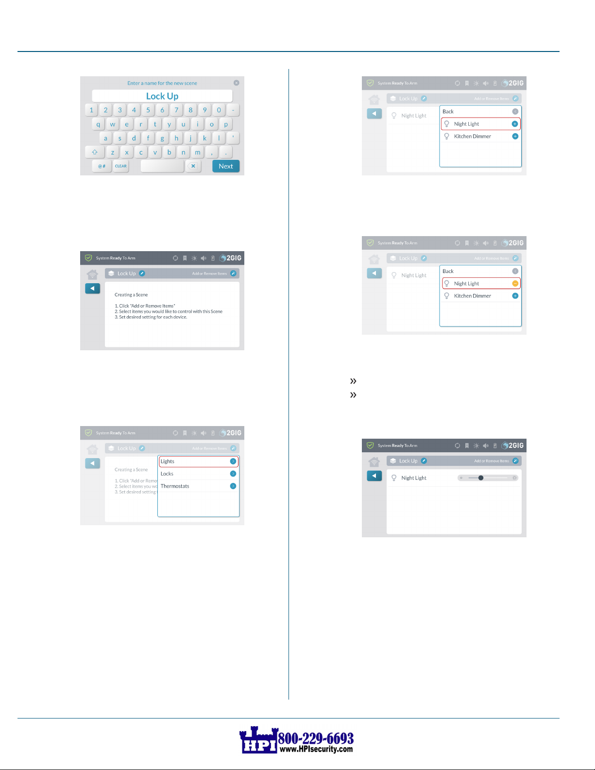
8 Smart Home Controls Proprietary &Confidential
Figure 11 Enter a Name for the New Scene
6. Create a new scene (see "Add a New Scene" on the previous
page) or tap the Scene that you want to edit.
7. At the <Scene Name> screen, tap Add or Remove Items.
Figure 12 EditScene >Add or Remove Items
8. Tap the arrow that corresponds to the desired smart home
control.
For example, tap the arrow next to Lights.
Figure 14 Add or Remove Items >Lights>Add Device
When the device is added to the scene, the icon changes to
YELLOW.
Figure 15 Add or Remove Items >Lights>Device Added
10. Choose one of these options:
To add other devices to the scene, tap Back.
To save the scene as is, tap any area outside of the dropdown menu to close it.
Any devices added to the scene appear in the list.
Figure 13 Add or Remove Items >Lights
9. Tap the plus (+)sign that corresponds to the desired devicein the
list.
For example, tap the plus (+)sign next to the device named
Home Theater Light.
44 Copyright © 2016 Nortek Security &Control LLC
11. Set the desired settings for each device in the scene. When the
scene is r un, it will perform the chosen actions for all devices in the
scene.
12.
Tap t when finished.
Execute a Scen e
To execute a scene:
1. Navigate to the Smart Home Controls menu. See "Navigate to
the Smart Home Controls Menu" on page 42.
Figure 16 Scene
Page 45
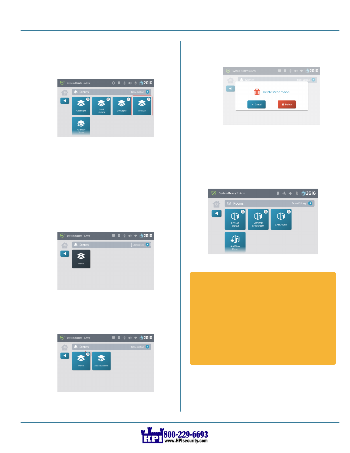
Proprietary &Confidential 8 Smart Home Controls
2. At the Home screen, tap Smart Home Controls.
3. At the Smart Home Controls menu, tap Scenes.
4. Tap the button for the desired scene.
For example, tap Lock Up.
Figure 17 Scenes
5. When the Scene <Name> was Executed message appear s,
tap OK or wait a few secondsfor the message to close
automatically.
6.
Tap t when finished.
Deleting a Scene
To delete scene:
1. Navigate to the Smart Home Controls menu. See "Navigate to
the Smart Home Controls Menu" on page 42.
2. At the Smart Home Controls menu, tap Edit Scenes.
Figure 19 Scene >Edit Scenes >Delete Scene
4. At the Delete Scene <Name> message, tap Delete.
Figure 20 Delete Scene Name Message
5.
Tap t when finished.
Add a NewRoom
Use the Ro oms screen to create customized settings for the smart home
controls in a specificroom. There isno functional limit on the number of
rooms that you can create for the system.
Figure 21 Rooms Screen
E x a m p l e s : W h e n t o C r e a t e
R o o m s
Figure 18 Scenes>Edit Scenes
This placesthe Scenes screen into edit mode.
3. While the system is in editing mode, tap the trash can icon that
corresponds to the scene to delete.
Copyright © 2016 Nortek Security &Control LLC 45
There are a wide variety of rooms that you can create.Some of
the more common include:
Fron t RoomCreate customized settings for your dwelling'sliving
room.
Master Bedroom Create customized settings for your
dwelling'smaster bedroom.
Basement Create customized settings for your home's
basement.
Add a New Room
To add a new room:
Page 46
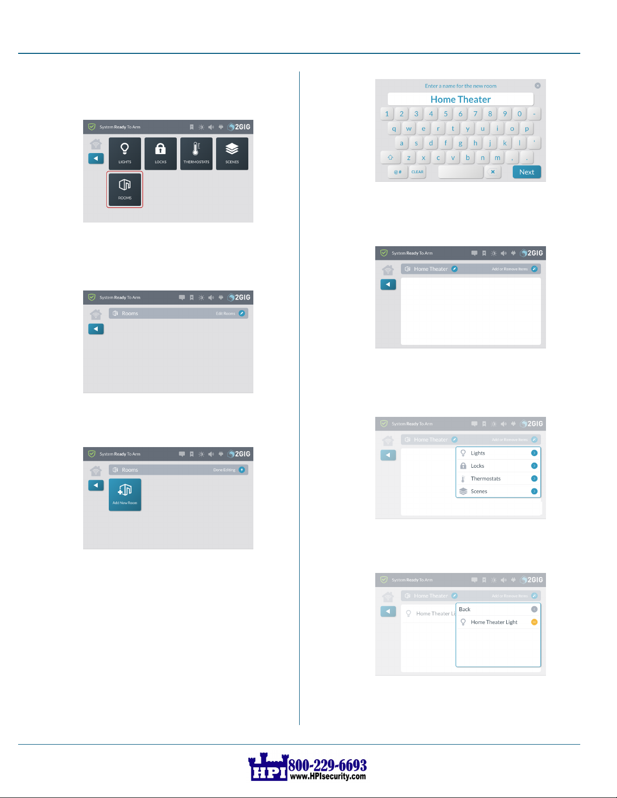
8 Smart Home Controls Proprietary &Confidential
1. Navigate to the Smart Home Controls menu. See "Navigate to
the Smart Home Controls Menu" on page 42.
2. At the Smart Home Controls screen, tapRooms.
Figure 24 Enter a Name for the New Room
6. At the <New Room Name>screen, tap Ad d or Remove Items.
Figure 22 Smart Home Controls >Rooms
This r eveals the Rooms screen.
3. At the Rooms screen, tap Edit Rooms.
Figure 23 Rooms >Edit Rooms
4. While in editing mode, tap Ad d New Room.
5. At the Enter a Name for the New Room screen, enter a name
and then tap Next.
For example, enter: Home Theater
Figure 25 Add or Remove Items
7. At the drop-down list, tap the type of device to add.
For example, tap Lights.
Figure 26 Add or Remove Items—Device Types
8. In the drop-down list, tap the device to add.
46 Copyright © 2016 Nortek Security &Control LLC
Page 47
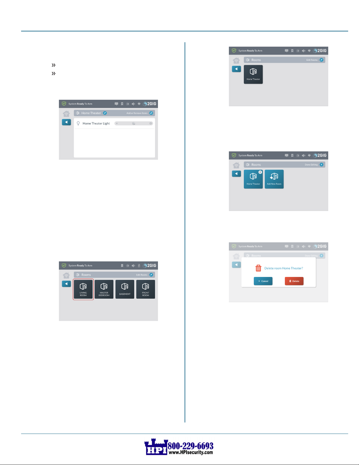
Proprietary &Confidential 8 Smart Home Controls
Figure 27 Add or Remove Items—Add Device
9. Choose one of these options:
To add other devices to the room, tap Back.
To save the room as is, tap any area outside of the dropdown menu to close it.
Any devices added to the room appear in the list.
Figure 30 Rooms >Edit Rooms
This placesthe Rooms screen into edit mode.
3. While the system is in editing mode, tap the trash can icon that
corresponds to the room to delete.
Figure 28 <Room Name>—Device Added
10.
Tap t when finished.
Access a Room
To access a room:
1. Navigate to the Smart Home Controls menu. See "Navigate to
the Smart Home Controls Menu" on page 42.
2. At the Home screen, tap Smart Home Controls.
3. At the Smart Home Controls menu, tap Rooms.
4. Tap the button for the desired room.
For example, tap Living Room.
4. At the Delete Roo m <Name> message, tap Delete.
Figure 31 Room >Edit Rooms >Delete Room
Figure 32 Delete Room Name Message
Figure 29 Rooms
5.
Tap t when finished.
Deleting a Ro om
To delete r oom:
1. Navigate to the Smart Home Controls menu. See "Navigate to
the Smart Home Controls Menu" on page 42.
2. At the Smart Home Controls menu, tap Edit Ro oms.
Copyright © 2016 Nortek Security &Control LLC 47
Page 48

8 Smart Home Controls Proprietary &Confidential
THIS PAGE INT ENTIONALLY LEFT BLANK
48 Copyright © 2016 Nortek Security &Control LLC
Page 49

9 SYSTEM INFO AND USAGE
This chapter includes the following information:
System Info and Usage 50
Histo ry 50
System Info 51
Dealer In fo 51
Copyright © 2016 Nortek Security &Control LLC 49
Page 50
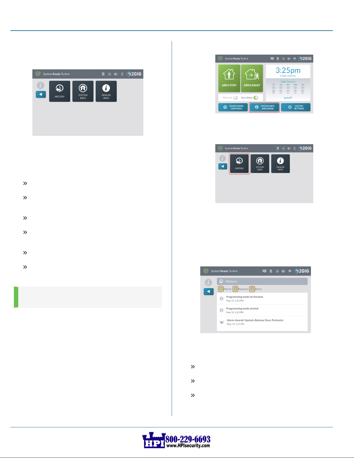
9 System Info and Usage Proprietary &Confidential
System Info and Usage
The System Info and Usage menu provides access to the system's
history, system information, and security provider's contact information.
Figure 1 System Info and Usage Menu
History
The Histo ry screen shows a chronologicallog of system events. Each
event is recorded with a date and time stamp:
System Armed/Disarmed: Keeps a record of when the system
is armed and disarmed.
Zone Bypassed/Un byp assed: Keeps a record of when zone
sensors are bypassed and unbypassed, and makes a note when
zones are bypassed or unbypassed by the installer.
Alarms Triggered/Cleared: Keeps a r ecord of when alarm
conditionsare triggered and cleared.
Alerts: Keeps a record of when theGC3 Panelor a zone issue
an alert. F or example, low battery, ACpower loss,or tamper
conditions.
*Programming Mode Started /Terminated: Keeps a record of
when the installer accesses and exitsthe Installer Toolbox.
*Walk Test Mo de Started /Terminat ed: Keeps a record of
when the installer starts and stops a Sensors Test and
ConsoleTest.
1. At the Home screen, tap System Info and Usage.
Figure 2 Home screen >System Info and Usage Button
2. At the System Inf o and Usage menu, tap History.
Figure 3 System Info and Usage Menu
This r eveals the Histo ry screen. See "Filtering the History
Screen" below.
Filtering the Hist ory Screen
You can filter the list in the History screen to show or hide alarms,
bypasses, or alerts.
NOTE: Events marked with an asterisk (*)always appear in
the log and cannot be filtered from view.
Navigate t o the History Screen
To navigate to the History screen:
Figure 4 History —Filter CheckBoxes
At the Hist ory screen, tap one of these check boxes to add or remove the
checkmark:
Alarms: Add a check mark to show alarm events.Remove the
checkmark to hide alarm events.
Bypasses: Add a check mark to show bypasses. Remove the
checkmark to hide bypasses.
Alerts: Add a check mark to show alerts. Remove the check
mark to hide alerts.
50 Copyright © 2016 Nortek Security &Control LLC
Page 51
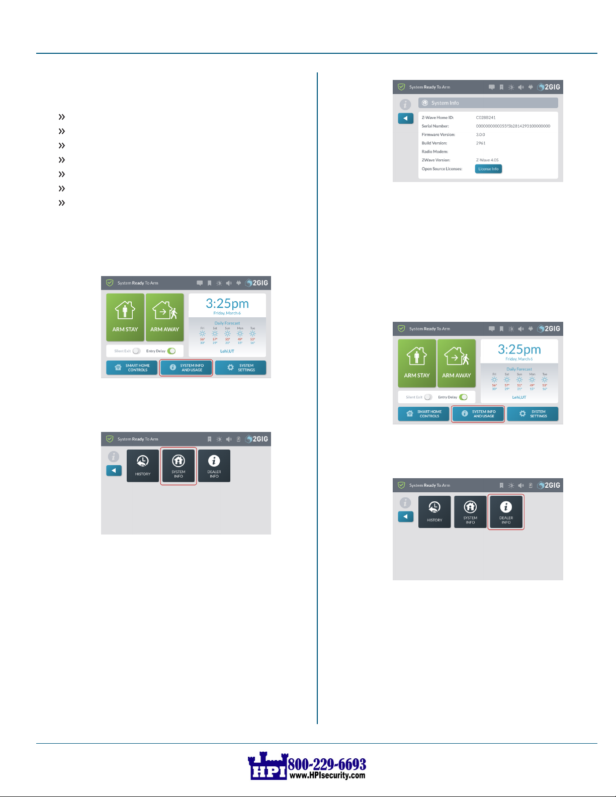
Proprietary &Confidential 9 System Info and Usage
System Info
The System Hist ory screen shows the following information about your
GC3 Panel(depending on the features that ar e active in your system):
Z-Wave Home ID
Serial Number
Firmware Version
Build Version
Radio Mo dem
Z-Wave Version
Open Source Licenses Information
Figure 7 System Info Screen
Navigate t o the System Info Screen
To navigate to the System Info screen:
1. At the Home screen, tap System Info and Usage.
Figure 5 Home screen >System Info and Usage Button
2. At the System Inf o and Usage menu, tap System Info.
Dealer Info
The Dealer In fo screen shows basic contact information for your 2GIG
alarm dealer.
Navigate t o the Dealer Info Screen
To navigate to the Dealer Inf o screen:
1. At the Home screen, tap the System Info and Usage button.
Figure 8 System Info and Usage Button
2. At the System Inf o and Usage menu, tap Dealer Info.
Figure 6 System Info and Usage Menu
This r eveals the System Info screen.
Figure 9 System Info and Usage Menu
This r eveals the Dealer Info screen. See "About the Dealer Info
Screen" below.
Abo ut th e Dealer Info Screen
For information about your 2GIG alarm dealer, navigate to the Dealer
Info screen. See "Navigate to the Dealer Info Screen" above.
Copyright © 2016 Nortek Security &Control LLC 51
Page 52

9 System Info and Usage Proprietary &Confidential
Figure 10 Dealer Info Screen
This screen provides you with the following information:
Dealer Name: Reveals the company name for your 2GIGalarm
dealer.
Dealer Address: Reveals the mailing address for your 2GIG
alarm dealer.
Dealer Phone #: Reveals your 2GIG alarm dealer's telephone
number.
Dealer URL: Reveals the web site url for your 2GIG alarm
dealer.
52 Copyright © 2016 Nortek Security &Control LLC
Page 53

10 SYSTEMSETTINGS
This chapter includes the following information:
Users 54
Soun ds 58
Bypass Sensors 59
Smart Home Settings Menu 60
Screen 70
Date/Time 72
SystemTests 72
FirmwareUpdate 74
Replace th e GC3 Cellular Radio Modu le 75
Copyright © 2016 Nortek Security &Control LLC 53
Page 54

10 SystemSettings Proprietary &Confidential
Users
The Users menu lets you add, edit, and delete users from the system.
NOTE: To use this feature, you must know the four-digit
Master User Code.
Types of User Codes
There are different types of user codes to provide users with access to
various system features:
IMPORTANT: Do Not Share Your User Codes. Operators
at the Central Station may need to review the codes used to
determine your identity. The codes entered may need to be
used as a decision-making tool for dispatching emergency
assistance.
User Code: A unique, four-digit code to identify different system
users and provide them with the ability to disarm the system.
Master User Code: A four-digit code typically known by one or
two members of a household. The default code is1111.To
secure this code, it is recommended that you immediatelychange
the default code to a unique one.
Duress Cod e: A four-digit code that you enter to silentlynotify
your Remote Service Provider of an emergency event, such as
being forcibly held against your willby an intruder .
Installer Code: A four-digit code that provides professional
installer's and 2GIG alarm dealers with access to the system's
programming functions.
Activating the Duress Code
The system supports a total of 100 four-digit pass codes (this includesboth
the Master User Code and the Duress Code). Although the Duress Code
is listed by default on the Users screen, it is not activated by default.
To activate the Duress Code:
1. At the Home page, tap System Settings.
2. Enter the Master User Code to access the System Settings
menu.
3. At the System Settings menu, tap Users.
been created: the Mast er User ( which is active) and the Duress
user (which is grayed out).
Figure 2 Users Screen
5. Tap the pencil icon next to the Duress user.
Figure 3 Users Screen > Edit Duress User
6. At the Edit Duress User screen, tap the Active button in the top
row.
Figure 4 EditDuress User > Active Button
7. At the Enter a cod e for u ser Duress screen, enter a unique
four-digit code for the duress user and tap Next.
Figure 1 System Settings> Users
4. This reveals the Users screen. If thisis the first time you are
adding a user, you willnotice that two (2) users have already
54 Copyright © 2016 Nortek Security &Control LLC
Page 55

Proprietary &Confidential 10 SystemSettings
Figure 5 DistressUser Code
8. At the Confirm code f or user Du ress, enter the code again
and tap Done.
9. At the Edit Duress User screen, tap the pencilicon in the Name
row if you want to change the user name.
Figure 8 Enter New User Name
6. At the Enter a cod e for User <Name> screen, enter a unique
four-digit code for the new user. T hen tap Next .
7.
NOTE: If you attempt to add a code that is already in
Figure 6 EditDuress User Screen
10.
Tap t when finished.
Add ing a User
You can add new users to the system. The system supports a total of 100
four-digit pass codes (thisincludesboth the Master User Code
andDuress Code).
To add a user:
1. At the Home screen, tap System Settin gs.
2. Enter the Master User Code to access the System Settings
menu.
3. At the System Settings menu, tap Users.
This r eveals the Users screen. If thisisthe first time you are
adding a user, you willnotice that two (2)users have already
been created. The Master User and the Du ress user.
4. Tap Add User.
At the Confirm code fo r user <Name> screen, re-enter the
four-digit code for the new user. T hen tap Next.
use, the system pr ompts you to enter a different
code. Every user code must be unique.
Figure 9 Enter a User Code
Figure 10 Confirm code for user <Name>
Figure 7 Users Screen > Add User
5. At the Enter a Name for the New User screen, enter a name
for the new user. Then tap Next.
Copyright © 2016 Nortek Security &Control LLC 55
The new user name and code appears in the Users page.
Page 56
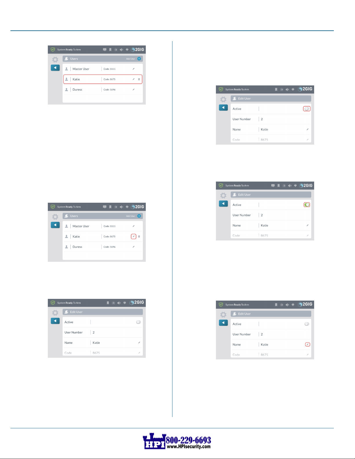
10 SystemSettings Proprietary &Confidential
Chan ge the User Status to Active or Inactive
To change the user status to activeor inactive:
1. Open the Edit User page. See "Editing a User" above.
2. If you want to make the user profile inactive, move the Active
slide control to the left.
Figure 11 User Screen > New User
8.
Tap t when finished or continue with the steps in "Editing a User"
below
Editing a User
To edit a user:
1. At the Home screen, tap System Settin gs.
2. Enter your four-digit user code to access the System
Settingsmenu.
3. Tap Users.
4. Tap the pencil icon next to the desired user.
3. If you want to make the user profile active, move the slide control
to the right. Thisis the factory default setting.
Figure 14 EditUser Screen > Inactive Status
Figure 12 User Screen > Edit User
5. Make the desired changes on the Edit User page. See "Editing
Options" below.
Figure 13 EditUser Screen
6.
Tap t when finished.
Editing Options
When editing a user, you have these options:
Figure 15 EditUser Screen > Active Status
Chan ge a User Name
To change a user name:
1. Open the Edit User page. See "Editing a User" above.
2. Tap the pencil icon next to the user name.
Figure 16 EditUser Screen > Edit Name
3. At the Enter a name for t he user screen, enter a new user
name.
56 Copyright © 2016 Nortek Security &Control LLC
Page 57
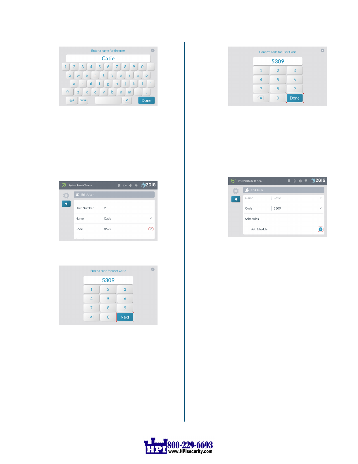
Proprietary &Confidential 10 SystemSettings
Figure 17 Enter User Name
4. Tap Done.
Chan ge a User Code
To change a user code:
1. Open the Edit User page. See "Editing a User" on the previous
page.
2. Tap the pencil icon next to the user code.
3. At the Enter a Code for User screen, enter a unique four-digit
code for the user. Then tap Next.
4. Enter the code again to confirm it.
5. Tap Done.
Add ing a User Schedule
To add a schedule:
1. Open the Edit User page. See "Editing a User" on the previous
page.
2. Scroll down to Sched ules.
3. Tap Add Schedu le.
4. Choose one of these options:
Add ing a Recurring Sch edu le
If a user requires access to your dwelling on a recurring schedule,
you can create a schedule for that user. For example, a
housekeeper or tutor might need recurr ing access to your home
on certain days of the week.
To add a recurring schedule:
a. Tap Recurring.
b. Place a check mark in the desired day of week boxes.
For example, place a check mar k in the Mon, Wed, and
Fri boxes.
c. Tap Set Start Time. Scroll to the desired Hour,
Minute, and AM/PM and tap Set.
d. Tap Set End Time. Scrollto the desired Hou r, Minute,
and AM/PM and tap Set.
Copyright © 2016 Nortek Security &Control LLC 57
Page 58
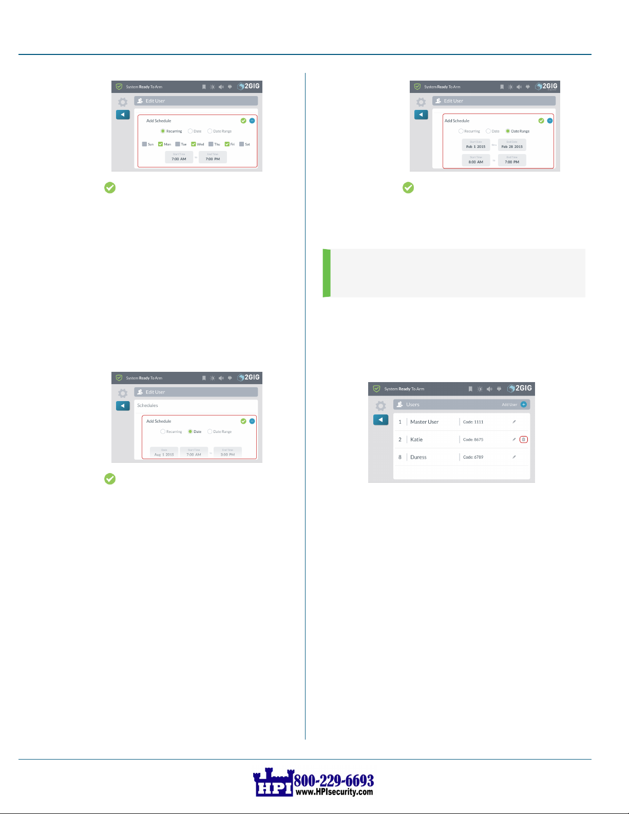
10 SystemSettings Proprietary &Confidential
e.
Tap to save the schedule.
Add ing a Date Schedule
If a user requires access to your dwelling on a specific date, you
can create a schedule for them. For example, a repairman might
need access to your home on a single date.
To add a date schedule:
a. Tap Date.
b. Tap Set Date. Scroll to the desired Month , Day, and
Year and tap Set.
c. Tap Set Start Time. Scroll to the desired Hour,
Minute, and AM/PM and tap Set.
d. Tap Set EndTime. Scrollto the desired Hour, Minute,
and AM/PM and tap Set.
e.
Tap to save the schedule.
Add ing a Date Range Schedule
If a user has a need to access your dwelling for a period of time,
you can create a schedule for them. For example, a visitor in your
home who needs accessfor a few weeks.
To add a date range schedule:
a. Tap Date Range.
b. Tap Set Start Date. Scroll to the desired Mont h, Day,
and Year and tap Set.
c. Tap Set End Date. Scroll to the desired Month, Day,
and Year and tap Set.
d. Tap Set Start Time. Scrollto the desired Hour,
Minute, and AM/PM and tap Set.
e. Tap Set EndTime. Scrollto the desired Hour, Minute,
and AM/PM and tap Set.
f.
Tap to save the schedule.
Delete a User
If an occupant of your dwelling moves away and no longer needs access to
your home, you can delete the user's profile.
NOTE: If you have shared the Master User Code or Duress
Code with the user, it isalso recommended that you change
those codes.
To delete a user:
1. At the Home screen, tap System Settings.
2. Enter your user code to accessthe System Settings menu.
3. Tap Users.
4. Tap the garbage can icon nextto the desired user.
5. At the Delete user screen, tap Delete.
Sounds
The Soun ds menu letsyou adjust the volume of the voice,chime,
doorbells, keypad tones, and system annunciations.
Adju st the Volume
To adjust the volume of a sound feature:
58 Copyright © 2016 Nortek Security &Control LLC
Page 59
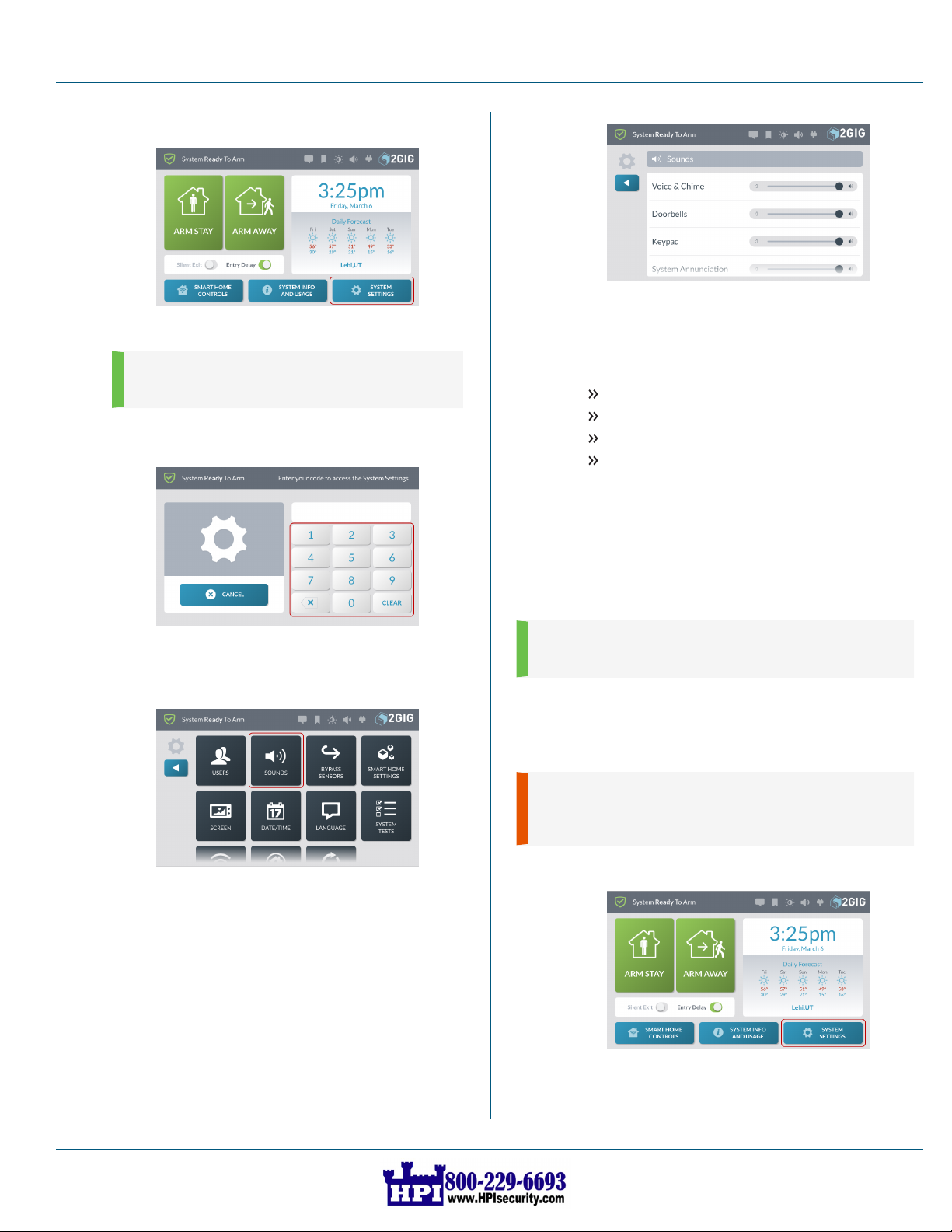
Proprietary &Confidential 10 SystemSettings
1. At the Home screen, tap System Settings.
Figure 21 Sounds Screen
Figure 18 Home Screen >System Settings
NOTE: To use this feature, you must know the four-
digit Master User Code.
2. At the Enter Your Code to Access the System Settings
screen, enter the four-digit Master User Code.
4. Swipe up or down to move the desired sound control into view.
5. Touch and holdthe desired control and then swipe to the left to
lower the volume or swipe to the right to raise the volume:
Voice &Chime
Doo rbells
Keypad
System Annunciat ion
6.
Tap t when finished.
Figure 19 Enter Your Code to Accessthe System Settings
3. At the System Settings menu, tap Sou nd s.
Figure 20 System Settings>Sounds
This r eveals the Soun ds screen.
Bypass Sensors
You can manuallybypassa sensor using the Bypass Sensors button in
the System Settin gs menu. When you need to bypass one or more
perimeter or interior sensors, it ismost common to manuallybypass the
sensor. There isalso an alternate method for bypassing a sensor called
Force Bypassing. See "Force Bypassing" on page 27.
NOTE: To use this feature, you must know the four-digit
Master User Code.
Manually Bypassin g a Senso r
When manuallybypassing a sensor, tap the Bypass Sensors option in
the System Settin gs menu to add the desired sensors to the Bypassed
Sensors list.
WARNING!! A bypassed burglary protection sensor does
NOTprovide security pr otection when the system is armed.
See "Force Bypassing" on page 27.
1. At the Home screen, tap System Settings.
Figure 22 Home Screen—System Settings Button
Copyright © 2016 Nortek Security &Control LLC 59
Page 60
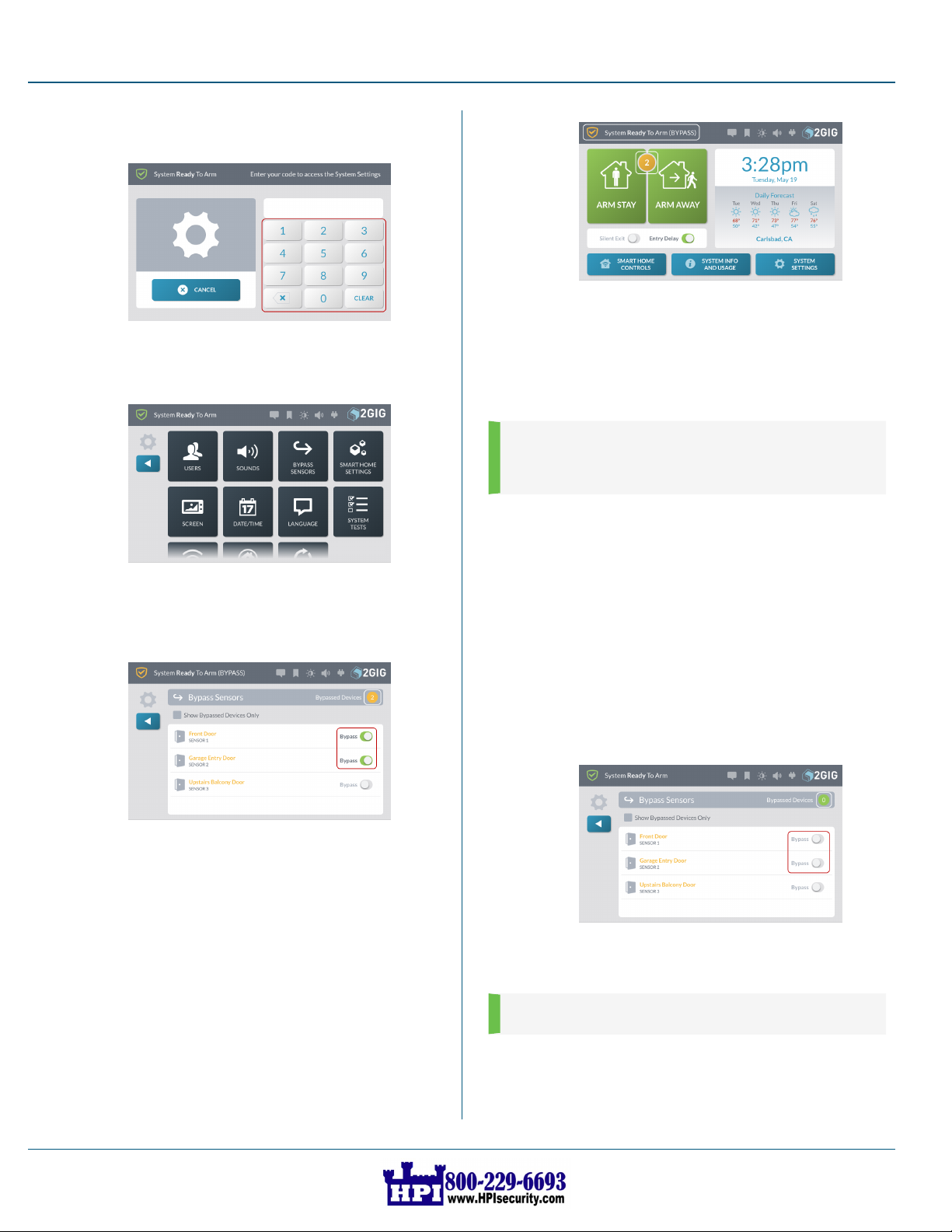
10 SystemSettings Proprietary &Confidential
2. At the Enter Your Code to Access the System Settings
screen, enter an active, four-digit user code.
Figure 26 System Ready to Arm (BYPASS) Status
Figure 23 Enter Your Code to Accessthe System Settings
3. At the System Settings menu, tap Byp ass Sen sors.
Figure 24 System Settings>BypassSensors
4. Onthe desired slide control, swipe right to add the sensor to the
system's list of Bypassed Devices.
7. Continue by arming the system. See "Arm the System" on page
26.
After the system is disarmed, bypassed sensors are automatically
removed from the system's Byp assed Sensors list, unless the Auto
Bypass fo r Manual Bypass feature isenabled.
NOTE: Consult your installer to determine if the Auto Bypass
for Manual Bypass feature isenabled. See the GC3
Installation & Programming Guide.
Removing Sensors from the Bypassed Sensors List
After the system is disarmed, bypassed sensors are automatically
removed from the system's Byp assed Sensors list, unless the Auto
Bypass fo r Manual Bypass feature isenabled. If you decide you want
to remove a sensor from the Bypassed Sensors list before you arm the
system, use the steps detailed here.
To remove a sensor from the Bypassed Sensors list:
1. At the Home screen, tap System Settings.
2. Enter the Master User Code to access the System Settings.
3. Tap Bypass Sen sors.
4. Move the slide control to the left for the desired sensor. This
removes the sensor from the system's Byp assed Senso rs list.
Figure 25 Bypassed Sensors Screen
5.
Tap t to return to the System Settings menu.
6.
Tap t to return to the Home screen.
The system bypasses the devices and itsstatus changes to
System Ready To Arm (BYPASS).
5.
Tap t when finished.
Smart Home Settings Menu
NOTE: This menu isonlyavailable to installers.
The Smart Home Settings menu provides installers with access to a
variety of Z-Wave settings for the GC3 Security & Automation System.
60 Copyright © 2016 Nortek Security &Control LLC
Page 61
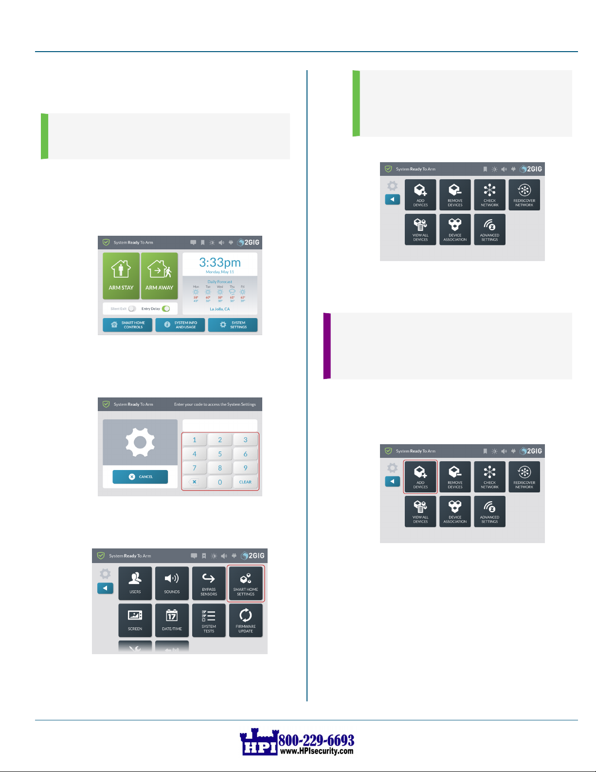
Proprietary &Confidential 10 SystemSettings
Installers can configure the system to give the Master User permission to
accessthe Smart Home Settings menu, users who know the Master
User code can access a variety of Z-Wave settings for the GC3 Security&
Automation System.
NOTE: The GC3 Panelignores any Command_Class_Basic
commands it receivesfrom other deviceson the Z-Wave
network.
Navigate t o the Smart Home Settings Menu
To navigate to the Smart Home Settings menu:
1. At the Home screen, tap System Settings.
Figure 27 Smart Home SettingsButton
2. At the Enter Your Code to Access the System Settings
screen, enter the system's four-digit Master User Code.
NOTE: Consult your installer to determine if the
Smart Home Settings menu has been enabled on
your system. Typically, thisbutton isgrayed out and
not available because the factory default setting for
this feature isDisabled but Visible.
This r eveals the Smart Home Settings menu.
Figure 30 Smart Home SettingsMenu
Add a New Device
TIP: Manufacturers may add Z-Wave devices to a network
in order to test them. To ensure successfuladdition of a
deviceto the GC3 Control Panel, remove the new device
before adding it to the networ k. See "Remove a Device" on
page 63.
To add a Z-Wave device to the network:
1. Navigate to the Smart Home Settings menu. See "Navigate to
the Smart Home Settings Menu" above.
2. At the Smart Home Settings menu, tap Add Devices.
Figure 28 Enter Your Code to Accessthe System Settings
3. At the System Settings menu, tap Smart Ho me Settings.
Figure 31 Smart Home Settings—Add Devices
The Listening for Devices to Add screen revealsthe Add
Devices Now message.
Figure 29 System Settings>Smart Home Settings
Copyright © 2016 Nortek Security &Control LLC 61
Page 62

10 SystemSettings Proprietary &Confidential
TIP: The Control Panel issues a double-beep when
a device is successfully added to the network.
Figure 32 Listening for Devices to Add—Add Devices Now
3. Walk to and trigger the device. For example, if you are adding a
Z-Wave light bulb, turn the light bulb ON.
Figure 35 Listening for Devices to Add—New Device
TIP: Typically, you can trigger a device on the
network by either powering the device OFF/ON,
pressing a button once or twice, or flipping a switch
on the device. Every device is different.
When the system discovers a device, the New device found
and Addin g device message appears.
5. (Optional) At the Listening for New Devices to Add screen,
tap Rename.
Figure 33 Adding Device
4. At the New device was added to the system message, tap
OK.
Figure 34 New Device was Added to the System Message
The newly discovered device appears in the Listening for
Devices to Add screen. Any device information captured during
the discovery process appears below the device name.
Figure 36 Listening for Devices to Add—Rename
6. At the Enter a name for t his device screen, use the
touchscreen keypad to enter a new device name.
For example, enter: Living Room Dimmer
Figure 37 Enter a name for this device
7. Tap Done.
The system reveals the new name on the Listening for
Devices to Add screen.
62 Copyright © 2016 Nortek Security &Control LLC
Page 63
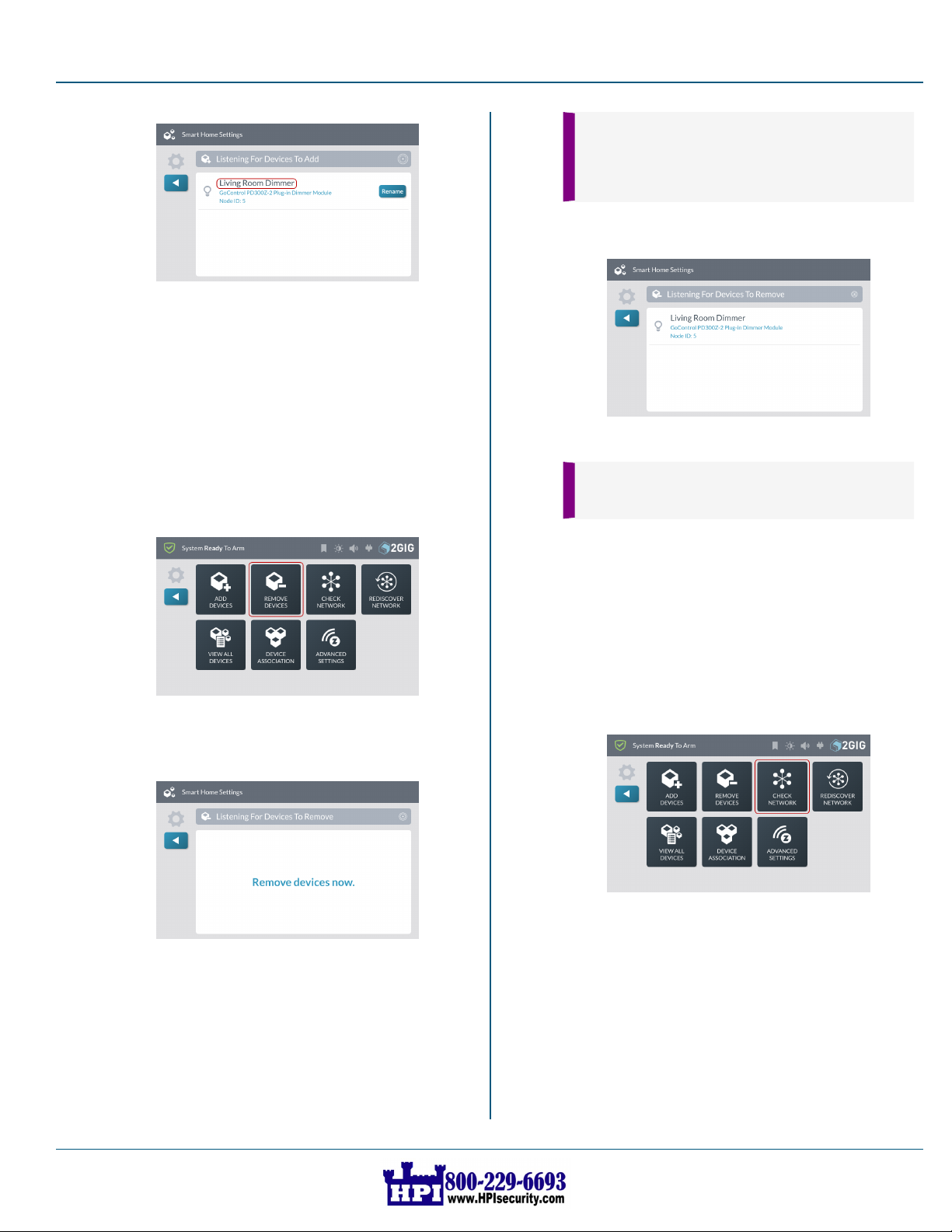
Proprietary &Confidential 10 SystemSettings
TIP: Typically, you can trigger a device on the
network by either powering the device OFF/ON,
pressing a button once or twice, or flipping a switch
on the device. Every device is different.
When the system successfully removes the device, it appears on
the Listening for Devices to Remove screen.
Figure 38 Listening for Devices to Add—New Device Name
From the Listening fo r Devices to Add screen, you can
continue by triggering the next desired deviceand then renaming
it as needed.
8.
Tap t to return to the Smart Home Settin gs menu.
Remove a Device
To remove a device from the network:
1. Navigate to the Smart Home Settings menu. See "Navigate to
the Smart Home Settings Menu" on page 61.
2. At the Smart Home Settings menu, tap Remove Devices.
Figure 39 Smart Home Settings—Remove Devices
The Listening for Devices to Remove screen appears.
Figure 41 Listening for Devices to Remove—Device Removed
TIP: The Control Panel issues a double-beep when
a device is successfully removed to the network.
5.
Tap t to return to the Smart Home Settin gs menu.
Check th e Network
Use the Ch eck Network feature to scan the smart home network for
unresponsive nodes. This can take several minutes and some of the smart
home functionswillbe unavailable until the checkiscomplete.
To perform a network check:
1. Navigate to the Smart Home Settings menu. See "Navigate to
the Smart Home Settings Menu" on page 61.
2. At the Smart Home Settings menu, tap Check Network.
Figure 42 Smart Home Settings—Check Network
Figure 40 Listening for Devices to Remove—Remove Devices
Now
4. Walk to and trigger the device on the network. For example, if you
are removing a Z-Wave light bulb, turn the light bulb ON.
Copyright © 2016 Nortek Security &Control LLC 63
3. At the Check Network screen, tap Start.
Page 64

10 SystemSettings Proprietary &Confidential
Figure 43 Check Network—Start
The system scans the network for unresponsive nodes and
indicates the status of each scanned node.
Figure 44 Check Network—Status
4. When the Check Network is complete you can see the status of
nodes in the network.
5.
Tap t to return to the Smart Home Settin gs menu.
Rediscover t he Network
After adding or removing devices fr om the network, the final step isto
rediscover the network. Thisupdates the system's communication r outes
so it communicateswith the newly added and previously added Z-Wave
devices.
To rediscover the network:
1. Navigate to the Smart Home Settings menu. See "Navigate to
the Smart Home Settings Menu" on page 61.
2. At the Smart Home Settings menu, tap Rediscover Network.
Figure 46 Rediscover Network—Start
While the system isrediscovering the network it displays the
status of each node asit is checked.
Figure 47 Rediscover Network—Status
When the rediscovery iscomplete, the Rediscover Network
screen with the Start button (shown above)appears again.
Reset the Controller
You can reset the Z-Wave controller to remove allZ-Wave devices from
the network and to reset the controller to its factory default state.
NOTE: Use thispr ocedure only in the event that the network
primary controller is missing or otherwise inoperable.
To reset the controller:
1. Navigate to the Smart Home Settings menu. See "Navigate to
the Smart Home Settings Menu" on page 61.
2. At the Smart Home Settings menu, tap Advanced Settin gs.
Figure 45 Smart Home Settings—RediscoverNetwork
3. At the Rediscover Network screen, tap Start.
64 Copyright © 2016 Nortek Security &Control LLC
3. At the Advan ced Settings menu, tap Reset Controller.
Figure 48 Smart Home Settings—Advanced Settings
Page 65
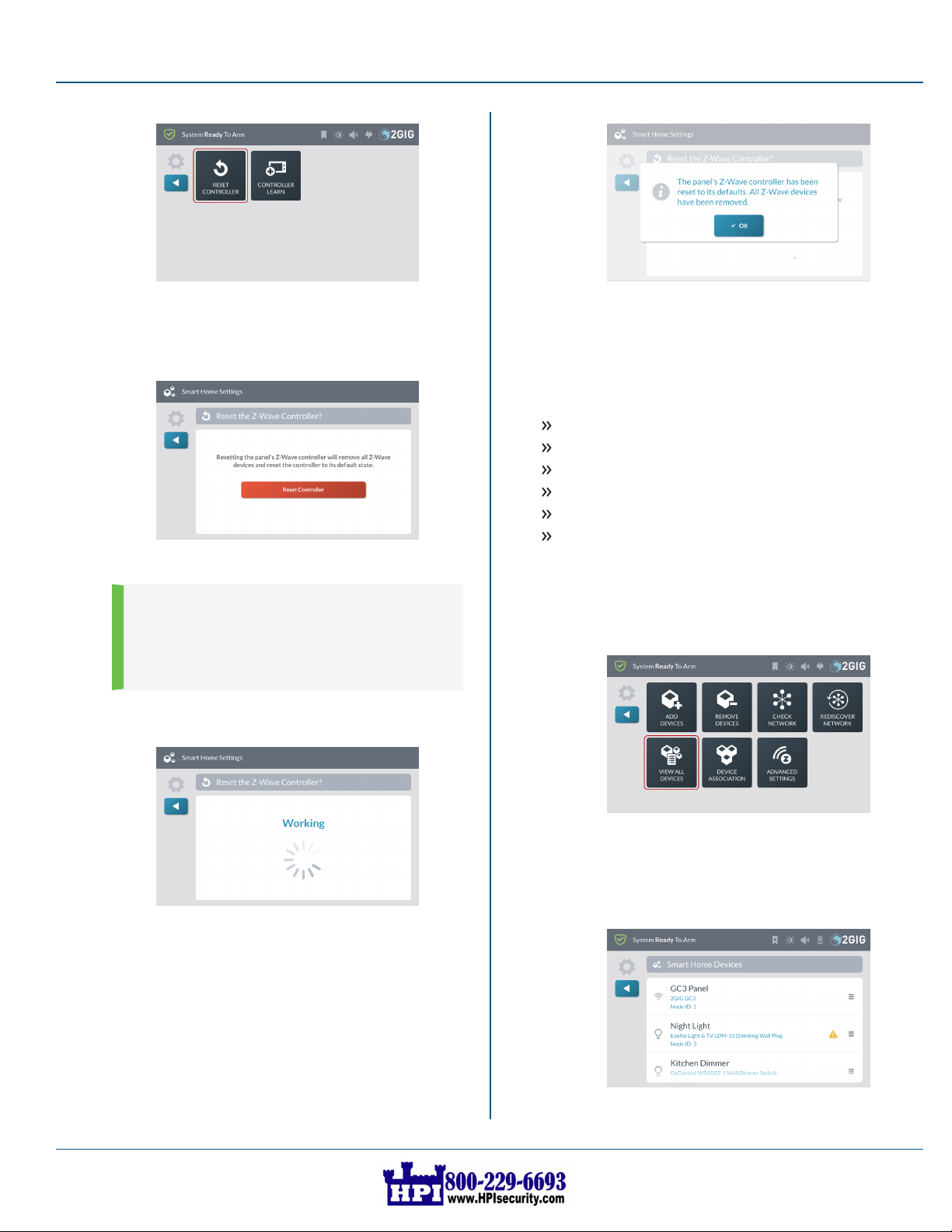
Proprietary &Confidential 10 SystemSettings
Figure 49 Advanced Settings—Reset Controller
4. At the Reset the Z- Wave Controller screen, tapReset
Con troller.
Figure 50 Reset the Z-Wave Controller—Reset Controller
NOTE: Resetting the controller willdelete allnode
information from the GC3 Control Panel. Any
devicesthat were part of the mesh network will need
to be manuallyremoved from the network before
they can be added to a network.
While the controller is being reset, the Working message
appears.
Figure 52 Z-Wave Controller Reset Message
View AllDevices
The View All Devices function lists all Z-Wave devices in the Control Panel
network and provides the following options, depending on the type and
current status of a device:
Con figure
Hide/Unhide
Identify
Remove
Rename
Replace
To view all network devices and access these options:
1. Navigate to the Smart Home Settings menu. See "Navigate to
the Smart Home Settings Menu" on page 61.
2. At the Smart Home Settings menu, tap View AllDevices.
Figure 53 Smart Home Settings—View AllDevices
3. At the Smart Home Devices screen, review the list of devices.If
you have added several devices, you can swipe up and down to
move through the list.
Figure 51 Reset the Z-Wave Controller—Working
5. When the controller isr eset, the following message appears. T ap
OK or wait a few seconds for the message to close automatically.
Copyright © 2016 Nortek Security &Control LLC 65
Page 66
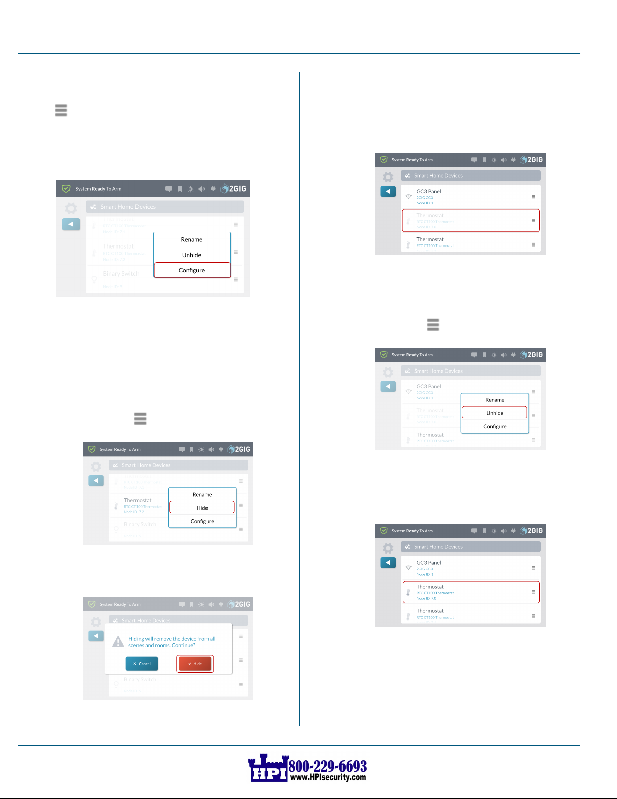
10 SystemSettings Proprietary &Confidential
Figure 54 Smart Home – View AllDevices
4. To view the options availablefor a device, tap the menu button (
).
Configure
The Configure option is device dependent, and only appears when a ZWave device hasspecialconfiguration options.
Figure 55 Smart Home – Configure Option
This option lets you enter configuration parameters that are found inthe
device'suser guide.
Hide/Unhide
Figure 57 Smart Home Devices – Hide Confirmation
2. Tap Hide to pr event the device from appearing on Smart Home
Control screens.
The device appears in gray text on Smart Home Devices
screen.
Figure 58 Smart Home Devices – Hidden Device
3.
Tap t to return to the Smart Home Settin gs menu.
To make a hidden device visibleon Smart Home Control screens:
1.
Tap the menu button ( ) next to the device and tap Unh ide.
The Hide/Unhide option deter mines whether or not a device appears on
Smart Home Control screens.
To hide a device on Smart Home Control screens:
1.
Tap the menu button ( ) next to the device and tap Hide.
Figure 56 Smart Home Devices – Hide
A confirmation screen appears.
Figure 59 Smart Home Devices – Unhide
The menu closes, the device appears in normal text on the Smart
Home Devices screen, and it also appears in Smart Home
Control screens.
Figure 60 Smart Home Devices – Unhidden Device
2.
Tap t to return to the Smart Home Settin gs menu.
66 Copyright © 2016 Nortek Security &Control LLC
Page 67

Proprietary &Confidential 10 SystemSettings
Identify
This option lets you identify a device from the control panel. Tapping
Identify activates the device(for example, a light module will tur n on and
then turn off). This feature can be helpful if you add multiple devices to the
system without renaming them at the time of installation.
Figure 63 Smart Home Devices – Remove Confirmation
2. Tap Remove to delete the device from the network.
3.
Tap t to return to the Smart Home Settin gs menu.
Rename
Figure 61 Smart Home Devices – Identify
Remove
This option lets you remove a non-communicating node fr om the system.
This option onlyappears for a device that is not communicating with the
system.
NOTE: Non-communicating devices are indicated byan
alert icon ( ).
To remove a non-communicating node from the system:
1.
Tap the menu button ( ) next to the non-communicating
deviceand tap Remove.
This option lets you rename devices that have already been added to the
system.
To rename a device:
1.
Tap the menu button ( ) next to the device and tap Rename.
Figure 64 Smart Home Devices – Rename
An onscreen keyboard appears.
Figure 62 Smart Home Devices – Remove
A confirmation screen appears.
Figure 65 Smart Home Devices – Enter a name for the device
2. Enter a new name for the device and tap Done.
The system reveals the new name on the Smart Home Devices
screen.
Copyright © 2016 Nortek Security &Control LLC 67
Page 68
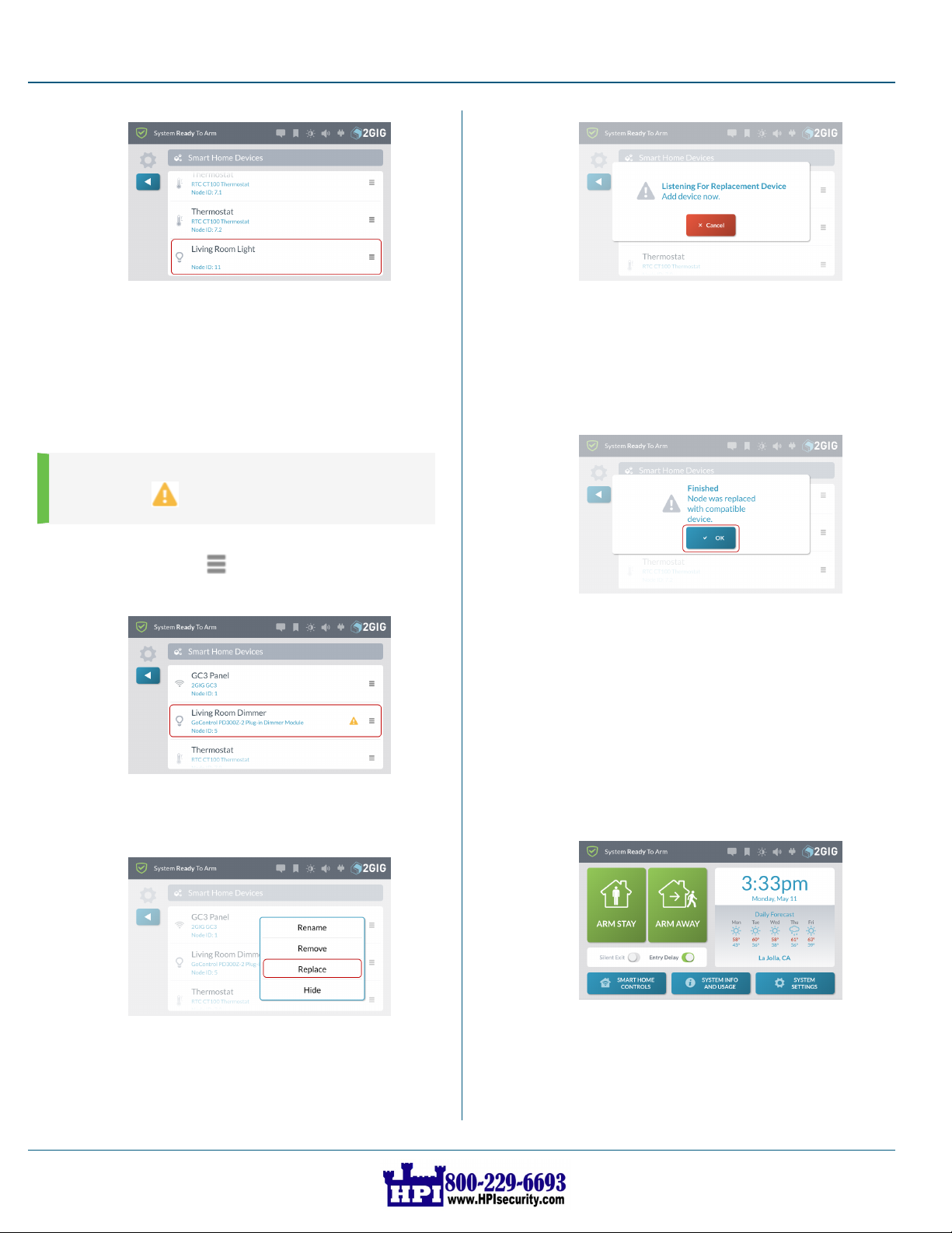
10 SystemSettings Proprietary &Confidential
Figure 66 Smart Home Devices – New Device Name
3.
Tap t to return to the Smart Home Settin gs menu.
Replace
This feature lets you replace a non-communicating device with an identical
devicemaintaining the same node number and other mesh network
settings. This makesit easier to replace a device that is no longer working
and isonly availablefor a non-communicating device.
NOTE: Non-communicating devices are indicated byan
alert icon ( ).
To replace a non-communicating device:
1.
Tap the menu button ( ) next to the non-communicating
deviceand tap Replace.
Figure 67 Smart Home Devices – Non-Communicating Device
2. Tape Replace.
Figure 69 Smart Home Devices – Listening For Replacement
Device
3. Walk to and trigger the replacement device on the network. For
example, if you are replacing a Z -Wave light bulb, turn the light
bulb ON.
A confirmation dialog appears when the replacement is finished.
Figure 70 Smart Home Devices – Replacement Finished
4. Tap OK to close the confirmation dialog.
5.
Tap t to return to the Smart Home Settin gs menu.
Associating Z -Wave Devices
The Association function provides a means of enabling individual networ k
devicesto communicate directlywith each other.
To associate Z-Wave devices:
1. At the Home screen, tap System Settings.
Figure 71 Home—System Settings
Figure 68 Smart Home Devices – Replace
A L istening F or Replacement Device screen appears.
68 Copyright © 2016 Nortek Security &Control LLC
2. Enter the Master User Code to access the System Settings
screen.
Page 69
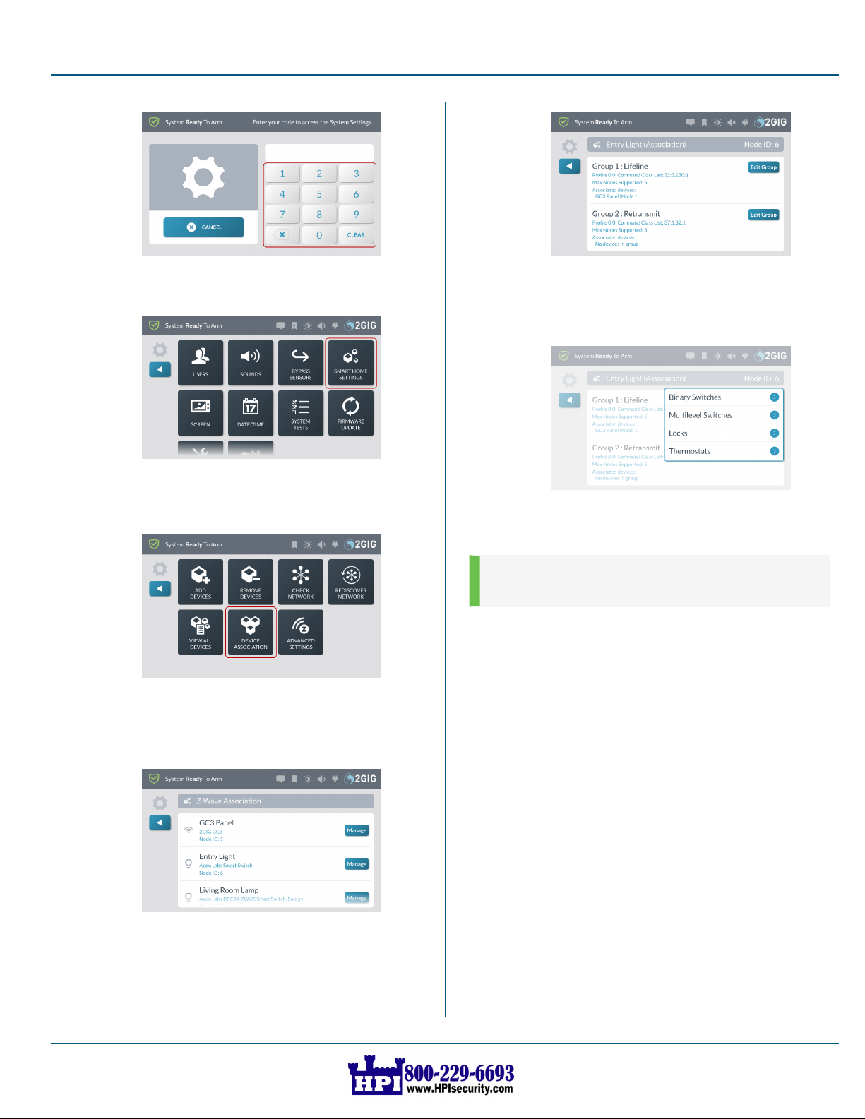
Proprietary &Confidential 10 SystemSettings
3. At the System Settings menu, tap Smart Ho me Settings on
both Control Panels.
Figure 72 System Settings—Smart Home Settings
4. At the Smart Home Settings menu, tap Device Associatio n.
Figure 73 Smart Home Settings—Advanced Settings
5. At the Z-Wave Association screen, tap the Manage button
next to the device that willact as the controller.
Figure 75 Z-Wave Association—EditGroup
7. Select the devices to be associated with the controller device and
tap 3.
Figure 76 Z-Wave Association Device
8.
Tap t to return to the Smart Home Settin gs menu.
NOTE: Refer to device documentation for information about
the association groups supported by the device.
Learn Controller
The GC3 Panelcan be added to an existing Z-Wave network as a
"secondary" controller (this processis also called "copy" or "replication").
When the GC3 Panel acts as a secondary controller, devicescan only be
added to or removed from the Z-Wave network at the primary controller.
Other than that, all functionsare available to either controller.
To add the GC3 Panel as a secondary controller for an existing Z-Wave
network:
1. At the existing controller, add the GC3 Panel to the Z-Wave
network. (If the existing controller is a GC3 Panel, see "Add a
New Device" on page 61. Otherwise, refer to the documentation
that came with the Z-Wave controller.)
2. At the Home screen on the secondary GC3 Panel, tap System
Settings.
Figure 74 Z-Wave Association—Manage
6. Tap Edit Group to select the Group for the association.
Copyright © 2016 Nortek Security &Control LLC 69
Page 70

10 SystemSettings Proprietary &Confidential
Figure 77 Home—System Settings
3. Enter the Master User Code to access the System Settings
screen.
4. At the System Settings menu, tap Smart Ho me Settings.
Figure 80 Advanced Settings—Controller Learn
The GC3 Paneldisplays a "Learning Z -Wave Controller"
message and waits for a signal from the primary controller. The
synchronization takestime, depending upon the number of ZWave devices in the network.
NOTE: If a new Z-Wave device is added to the
network, the secondary controller must be relearned into the network.
Screen
Use the Screen feature to adjust the screen br ightness, dim brightness,
backlight timeout, and to place the touchscreen into clean mode.
NOTE: To use this feature, you must know the four-digit
Master User Code.
Navigating t o Screen
1. At the Home screen, tap System Settings.
Figure 78 System Settings—Smart Home Settings
5. At the Smart Home Settings menu, tap Advanced Sett ing s.
Figure 81 Home Screen >System Settings
2. At the Enter Your Code to Access the System Settings
screen, enter an active, four-digit user code.
Figure 79 Smart Home Settings—Advanced Settings
6. At the Advan ced Settings menu, tap Controller Learn.
70 Copyright © 2016 Nortek Security &Control LLC
Page 71
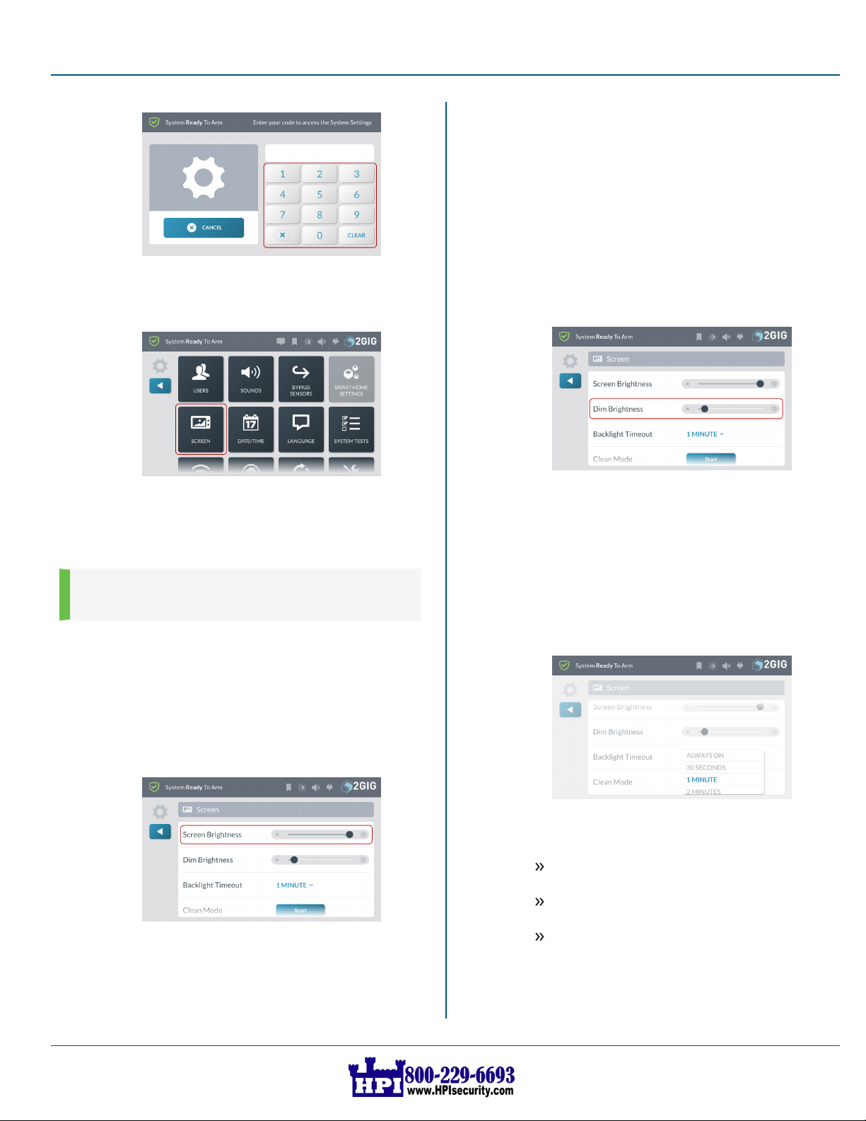
Proprietary &Confidential 10 SystemSettings
3.
Tap t to return to the System Settings menu.
4.
Tap t to return to the Home screen.
Adju stin g the Dim Brightness
The Dim Brightnessrefers to the brightness level of the touchscreen when
backlit.
To adjust the dim br ightness:
1. Navigate to Screen. See "Navigating to Screen" on the previous
page.
Figure 82 Enter Your Code to Accessthe System Settings
3. At the System Settings menu, tap Screen.
2. Onthe Dim Brightness slide control, swipe left to lower the
dimmer brightness. Swipe right to increase the dimmer
brightness.
Figure 83 System Settings>Screen
This r eveals the Screen screen.
Adju stin g the Screen Brightness
NOTE: This feature is availableonly when the system is set
to demo mode.
Adjust the screen brightness to improve the readabilityof the text and
images on the touchscreen and to avoid eye discomfort indarker
environments or at night.
To adjust the screen brightness:
1. Navigate to Screen. See "Navigating to Screen" on the previous
page.
2. Swipe the Screen Bright ness slide control to the left or right to
decrease or increase the brightness.
Figure 84 Screen—Screen Brightness
Figure 85 Screen—Dim Brightness
3.
Tap t to return to the System Settings menu.
4.
Tap t to return to the Home screen.
Adju stin g the Backlight Timeout
To adjust the timeout interval for the backlight:
1. Navigate to the Screen screen. See "Navigating to Screen" on
the previouspage.
Figure 86 Screen—Backlight Timeout
2. Choose one of these options from the list:
Always On: Thisoption requires the most battery
power.
30 Seconds: T his option conserves the most battery
power. Thisis the factory default setting.
1 Minute-10 Minutes: Select the desired timeout
interval.
Copyright © 2016 Nortek Security &Control LLC 71
Page 72
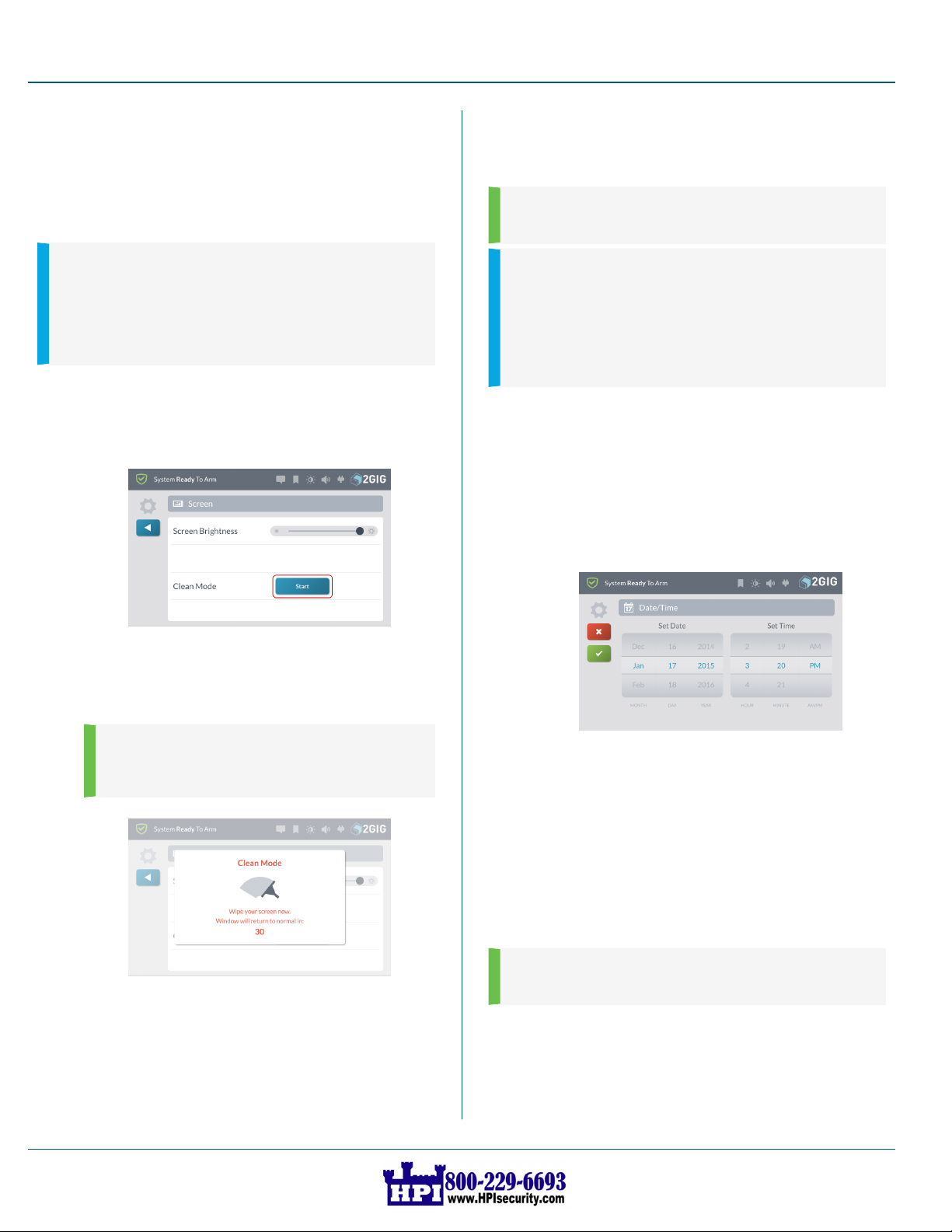
10 SystemSettings Proprietary &Confidential
3.
Tap t to return to the System Settings menu.
4.
Tap t to return to the Home screen.
Placing the System into Clean Mode
Alwaysplace the system into Clean Mode before wiping the
touchscreen.This will help you to avoid setting off a false alarm or
changing system settings when cleaning the touchscreen.
Date/Time
The Date/Time screen letsyou modify the time displaying on the GC3
Panel's touchscreen.The date and time are also logged on system alarms
and reports.
NOTE: To use this feature, you must know the four-digit
Master User Code.
IMPORTANT: Always wipe the touchscreen with a soft, dry,
microfiber cloth that is specially designed for cleaning
sensitive surfaces. Do not use abrasive cloths (for example,
no paper towels and no tissue paper). Do not use harsh
chemicals or liquids (for example, no ammonia, no alcoholbased cleaners, and no water).
To place the panel into clean mode:
1. Navigate to the Screen screen. See "Navigating to Screen" on
page 70.
2. Scroll to Clean Mode. Then tap Start.
Figure 87 Screen—Clean Mode
A 30-second countdown timer appears and the system blocks all
touch interactions from inadvertently activating buttons during
cleaning.
IMPORTANT: If the system hasa Cellular Radio Module
installed, the date and time willbe set automatically by your
Alarm Provider's Central Station. For systemswithout
cellular capabilities,the installer will typicallyset the system
date and time during the installation process.The installer
may also program the system to automaticallyadjust for
Daylight Saving T ime.
Set the Date/T ime
To set the system date:
1. At the Home screen, tap System Settin gs.
2. At the System Settings menu, enter the system's Master User
Code.
3. Tap Date/Time.
The system reveals the Date/Time screen.
NOTE: Tap the Home or Emergen cy button to
cancelthe Clean Mode countdown and return to the
Home screen.
4. Scroll through the date options select the appropriate Month,
Day, and Year.
5. Scroll through the time options to select the appropriate Hour,
Minute, and choosebetween AM/PM.
6. Tap ü when finished.
Figure 89 Date/Time Screen
SystemTests
To ensure continued protection and proper system operations, it is
important to perform a sensor and console test on a weeklybasis.
NOTE: To use this feature, you must know the four-digit
Figure 88 Clean Mode
3. Wipe the touchscreen with a soft, dry, microfiber cloth that is
specially designed for cleaning sensitivesurfaces.
72 Copyright © 2016 Nortek Security &Control LLC
Navigate t o System Tests
To navigate to the System Tests module:
Master User Code.
Page 73
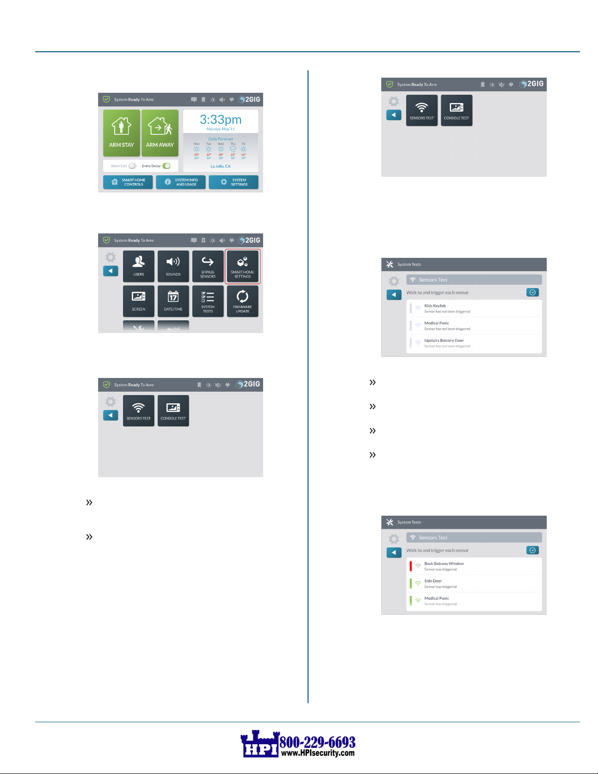
Proprietary &Confidential 10 SystemSettings
1. At the Home screen, tap System Settings.
2. Tap Sensors Test.
2. Enter the Master User Code to access the SystemSettin gs
menu.
This placesthe GC3 Panel into Walk Test Mode and transmits a
Walk Test Started report to the Central Station.
3. At the Sensors Test screen, review the list of sensors installed
with your system.
3. Tap SystemTests.
This r eveals the Systems Tests menu.
4. Tap one of these buttons to choose the test type:
Sensors Test : Tests the wirelesssignal between the
GC3 Paneland installed sensors. See "Performing a
Sensors T est" below.
Con sole Test: Tests the function of the GC3 Panel's
audio and buttons. See "Performing a Console Test" on
the next page.
Performing a Sensors Test
To perform a sensors test:
1. Navigate to the System Tests menu. See "Navigate to System
Tests" on the previous page.
4. Walk to and trigger each sensor in the list:
For Door/Wind ow Contact Senso rs:Open and then
close the door or window.
For Motion Detecto rs: Stay outside of the protected
area for five (5) minutes. Then, walk through the area.
For Panic Buttons, Keyfobs, and Wireless
Keypads Press a key or button on the device.
For Smoke/Heat/Freeze Alarms, Carbon Mono xide
Detectors, or Glass Break Det ectors: Press the
product's Test button. See the Installation Instructions
that came with the product for help locating the test
button.
When testsare successful, a GREENbar appears to the left of
the test name.This indicates the sensor is operating and the
wireless signal strength was good.
Copyright © 2016 Nortek Security &Control LLC 73
Page 74
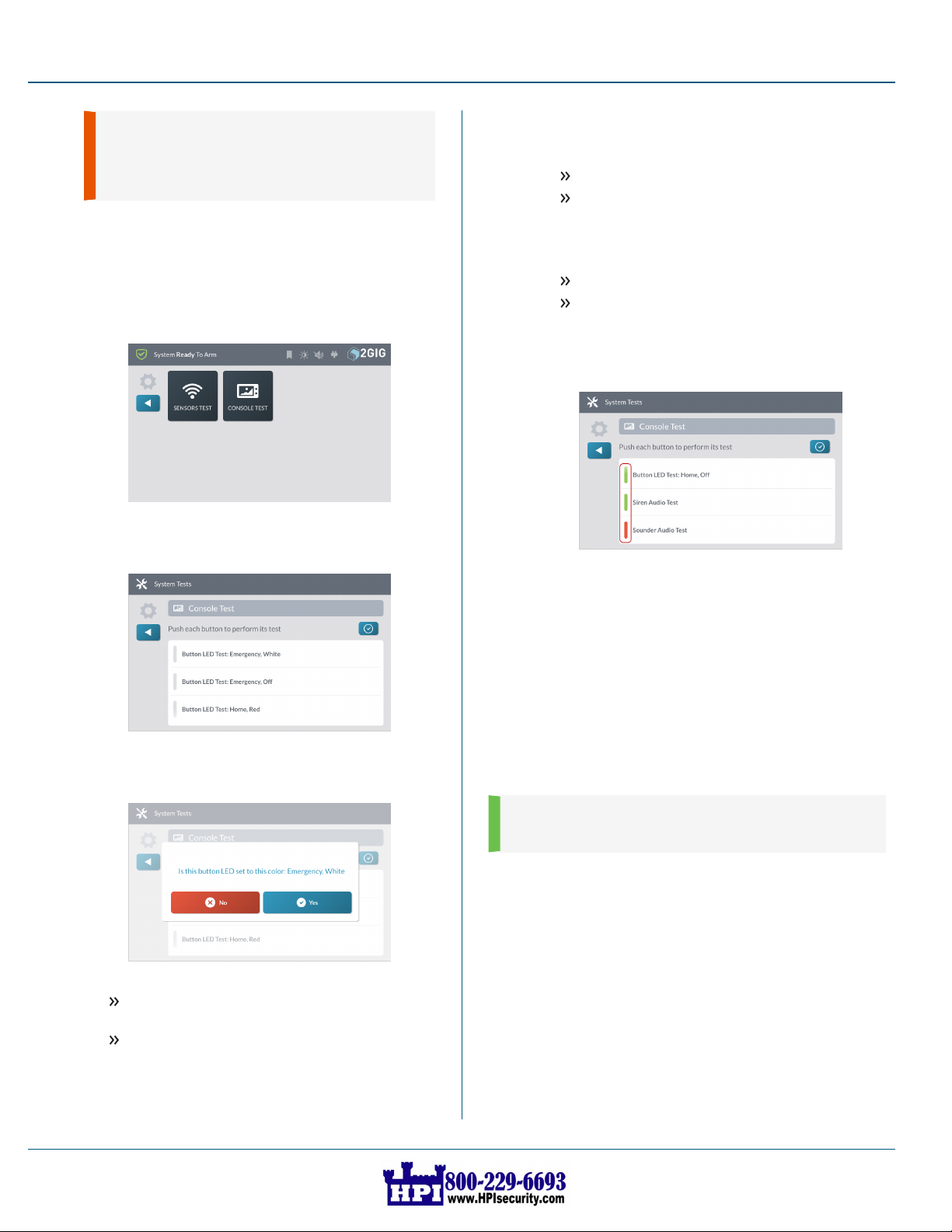
10 SystemSettings Proprietary &Confidential
WARNING!! If a REDbar appears, it indicates the
test failed. To protect your dwelling and its
occupants from adverse events, contact your 2GIG
alarm dealer for technical assistance.
5.
Tap the t button .
Performing a Console Test
To perform a console test:
1. Navigate to the System Tests menu. See "Navigate to System
Tests" on page 72.
2. Tap Conso le Test.
This r eveals the Console Test screen.
8. Scroll down the screen and tap Siren Aud io Test.
This tests the internal siren on the GC3 Panel. When the test is
complete, tap one of thesebuttons:
No: Tap this button if you did not hear the siren.
Yes: T ap thisbutton if you heard the siren.
9. Scroll down the screen and tap Sound er Audio Test.
This tests the sounder on the GC3 Panel. When the test is
complete, tap one of thesebuttons:
No: Tap this button if you did not hear the sounder.
Yes: T ap thisbutton if you heard the sounder.
10. If any of the testsfailed, a REDbar appears next to the test name
as shown in the example below. Contact your 2GIG alarm dealer
for technicalsupport.
11.
Tap the t button.
3. Tap Button LEDTest; Emergency, White.
A confirmation message appear s.
6. Tap one of the following buttons:
No: Tap this button if the LED does not match what is
described in the message.
Yes: T ap thisbutton if the LEDmatcheswhat is
described in the message.
7. Repeat the above steps for each listed Button LED test.
FirmwareUpdate
For the GC3 Panelto work properly, special firmware is required. This
firmware contains the background programming information that tells the
GC3 Panelhow to do things. As2GIG makes improvements to the system,
new firmware updates are released and can be installed as described
here.
Installing USB Firmware Updates
If your dealer providesyou with a firmware update on a USB drive, you
can connect that device to the USB port to update your system. This gives
both the Master User the ability update the system's firmware as needed.
NOTE: To use this feature, you must know the four-digit
Master User Code.
To install the firmware update:
1. Insert a USB thumb drivestoring the desired firmware version
into the USB port at the top of the GC3 Panel.
74 Copyright © 2016 Nortek Security &Control LLC
Page 75

Proprietary &Confidential 10 SystemSettings
Top
Bottom
Figure 92 Update Firmware System Icon
2. At the Update Firmware screen, tap Update Firmware.
Figure 90 GC3 Control Panel—Front View
2. When the Update system icon and the Firmware Update
Available from USB Device message appear s, tap Update.
Figure 91 Firmware Update Available from USBDevice
NOTE: If you do not tap Up date in time, see
"Installing USB Firmware Updates (SystemIcon)"
below.
The GC3 Panelturns BLACK and in a few moments, the
Upd atin g Firmware message appears.
IMPORTANT: During the update process, do NOT
disconnect the GC3 Panel fr om itspower source
and do NOT remove the USB thumb drive from the
panel until the update iscomplete.
When the update is complete, the system r estarts automatically
and a new message appears in the system's Inbox to notify users
that the firmware update was successful. See "Using the Inbox"
on page 16.
Installing USB Firmware Updates (SystemIcon)
To install an update:
1. Tap the Up date system icon whilethe USB thumb drive is
inserted.
Figure 93 Update Firmware Screen
The GC3 Panelturns BLACK and in a few moments, the
Upd atin g Firmware message appears.
IMPORTANT: During the update process, do NOT
disconnect the GC3 Panel fr om itspower source
and do NOT remove the USB thumb drive from the
panel until the update iscomplete.
When the update is complete, the system r estarts automatically
and a new message appears in the system's Inbox to notify users
that the firmware update was successful. See "Using the Inbox"
on page 16.
Replace the GC3 Cellular Radio Module
After your system is installed, if your dealer supplies you with a new 2GIG
cellular radio module, you can use the following instructions to installit into
your GC2 Control Panel.
To replace the Cellular Radio Module into a system:
1. From the Home screen, tap System Settings.
2. From the System Settings menu, tap Cell Radio Swap.
Copyright © 2016 Nortek Security &Control LLC 75
Page 76
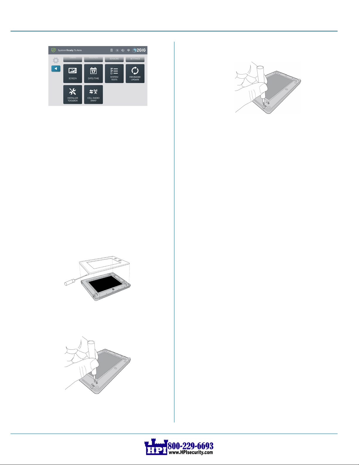
10 SystemSettings Proprietary &Confidential
3. Install the screw into the LOCK position on the left. This locksthe
hinged door on the GC3 Control Panel.
3. Tap Begin.
4. Remove the hinged door from the GC3 Control Panel.
5. Pull the tab to remove the Cellular Radio Module.
6. Insert the new GC3 Cellular Radio Module until it clicksinto place.
7. (Optional) Install the lock on the Cellular Radio Module bay door .
See "(Optional) Lock/Unlock the Cellular Radio Module Door"
below.
8. Replace the hinged door.
9. Tap Done.
(Optional) Lock/Unlo ck the Cellular Radio Module Door
The Cellular Radio Module fits into the bayon the side of the GC3 Panel
and features a built-in door lock under the faceplate. The Control Panel
shipswith the door -lock screw in the UNLOCK position. T o limit the
possibilityof someone removing the door, installers have the option of
moving the screw to the LOCK position.
To lockand unlock the Cellular Radio Module door:
1. Use your fingertips or carefullyinsert a screwdriver at the edge of
the faceplate. Then gently pry the faceplate fr om the chassis.
Figure 96 GC3 Panel—LOCK position
4. Snap the faceplate backon the GC3 Control Panel.
Figure 94 GC3 Panel—Removeable F aceplate
2. Remove the door-lock screw from the UNLOCK position on the
right.
Figure 95 GC3 Panel—UNLOCK position
76 Copyright © 2016 Nortek Security &Control LLC
Page 77

Page 78

A L A R M D E A L E R I N F O R M A T I O N
Compan y Name:
Your Accou nt Number:
Installation Date:
R E M O T E S E R V I C E P R O V I D E R
Compan y Name:
Your Accou nt Number:
Installation Date:
10004670 A| Proprietary &Conf idential | Nortek Internal Use & Beta Test Program Participants Only
Page 79

Proprietary &Confidential
Index
2
2-way voice 8
microphone 8
24-hour backup
battery 8
A
accessories 8
alarm dealers 6
alarms
false 10
alerts 9
C
cellular radio module 8, 75
D
date 8
distributors 6
document conventions 6
N
navigation
touchscreen 6
S
safety
notations 6
services
technicalsupport 6
speaker 8
support
services 6
system
capabilities 8
features 8
T
technicalsupport 6
time 8
touchscreen
display 8
navigation 6
trouble alerts 9
typographic conventions 6
F
false alarms 10
features 8
G
guide
about 6
I
installation 9
cellular radio module 75
M
microphone 8
U
usb port 8
location 8
V
vocabulary 8
W
weather 8
Z
Z-Wave
devices 8
zone 9
Copyright © 2015 Nortek Security &Control LLC 79
Page 80

Proprietary &Confidential
800-229-6693
www.HPIsecurity.com
An Authorized Dealer
Call
THIS PAGE INT ENTIONALLY LEFT BLANK
80 Copyright © 2015 Nortek Security &Control LLC
 Loading...