


OPERATING INSTRUCTIONS AND SPECIFICATIONS
NI 9403
32-Channel, TTL Digital Input/Output Module
Français Deutsch
ni.com/manuals

This document describes how to use the National Instruments 9403 and includes specifications and pin assignments for the NI 9403. Visit ni.com/info and enter rdsoftwareversion to determine which software you need for the modules you are using. For information about installing, configuring, and programming the system, refer to the system documentation. Visit ni.com/info and enter cseriesdoc for information about C Series documentation.
Note The safety guidelines and specifications in this document are specific to the NI 9403. The other components in the system might not meet the same safety ratings and specifications. Refer to the documentation for each component in the system to determine the safety ratings and specifications for the entire system. Visit ni.com/info and enter cseriesdoc for information about C Series documentation.
NI 9403 Operating Instructions and Specifications |
2 |
ni.com |
Safety Guidelines
Operate the NI 9403 only as described in these operating instructions.
Hot Surface This icon denotes that the component may be hot. Touching this component may result in bodily injury.
Safety Guidelines for Hazardous Locations
The NI 9403 is suitable for use in Class I, Division 2, Groups A, B, C, D, T4 hazardous locations; Class I, Zone 2, AEx nA IIC T4, and Ex nA IIC T4 hazardous locations; and nonhazardous locations only. Follow these guidelines if you are installing the NI 9403 in a potentially explosive environment. Not following these guidelines may result in serious injury or death.
Caution Do not disconnect I/O-side wires or connectors unless power has been switched off or the area is known to be nonhazardous.
Caution Do not remove modules unless power has been switched off or the area is known to be nonhazardous.
© National Instruments Corp. |
3 |
NI 9403 Operating Instructions and Specifications |

Caution Substitution of components may impair suitability for Class I, Division 2.
Caution For Zone 2 applications, install the system in an enclosure rated to at least IP 54 as defined by IEC 60529 and EN 60529.
Caution For Zone 2 applications, connected signals must be within the following limit:
Capacitance.......................... |
0.02 μF max |
Special Conditions for Hazardous Locations Use in Europe
This equipment has been evaluated as Ex nA IIC T4 equipment under DEMKO Certificate No. 07 ATEX 0626664X. Each module is marked  II 3G and is suitable for use in Zone 2 hazardous locations. If you are using the NI 9403 in Gas Group IIC hazardous locations or in ambient temperatures of –40 °C ≤ Ta ≤ 70 °C, you must use the device in an NI chassis that has been evaluated as EEx nC IIC T4, Ex nA IIC T4, or Ex nL IIC T4 equipment.
NI 9403 Operating Instructions and Specifications |
4 |
ni.com |

Special Conditions for Marine Applications
Some modules are Lloyd’s Register (LR) Type Approved for marine applications. To verify Lloyd’s Register certification, visit ni.com/certification and search for the LR certificate, or look for the Lloyd’s Register mark on the module.
Caution To meet radio frequency emission requirements for marine applications, use shielded cables and install the system in a metal enclosure. Suppression ferrites must be installed on power supply inputs near power entries to modules and controllers. Power supply and module cables must be separated on opposite sides of the enclosure and must enter and exit through opposing enclosure walls.
© National Instruments Corp. |
5 |
NI 9403 Operating Instructions and Specifications |
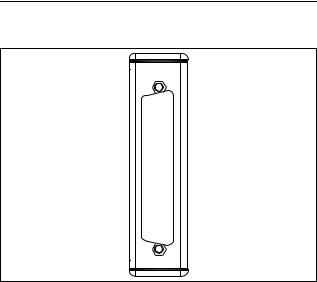
Connecting the NI 9403
The NI 9403 has a 37-pin DSUB connector that provides connections for the 32 digital input/output channels.
DIO16 |
20 |
1 |
DIO0 |
|
2 |
DIO1 |
|||
DIO17 |
21 |
|||
3 |
DIO2 |
|||
DIO18 |
22 |
|||
4 |
DIO3 |
|||
DIO19 |
23 |
|||
5 |
DIO4 |
|||
DIO20 |
24 |
|||
6 |
DIO5 |
|||
DIO21 |
25 |
|||
7 |
DIO6 |
|||
DIO22 |
26 |
|||
8 |
DIO7 |
|||
DIO23 |
27 |
|||
9 |
COM |
|||
COM |
28 |
|||
10 |
COM |
|||
COM |
29 |
|||
11 |
DIO8 |
|||
DIO24 |
30 |
|||
12 |
DIO9 |
|||
DIO25 |
31 |
|||
13 |
DIO10 |
|||
DIO26 |
32 |
|||
14 |
DIO11 |
|||
DIO27 |
33 |
|||
15 |
DIO12 |
|||
DIO28 |
34 |
|||
16 |
DIO13 |
|||
DIO29 |
35 |
|||
17 |
DIO14 |
|||
DIO30 |
36 |
|||
18 |
DIO15 |
|||
DIO31 |
37 |
|||
19 |
RSVD |
|||
|
|
Figure 1. NI 9403 Pin Assignments
NI 9403 Operating Instructions and Specifications |
6 |
ni.com |
Each channel has a DIO pin to which you can connect a digital input or output device. The 32 DIO channels are internally referenced to COM, so you can use any of the four COM lines as a reference for the external signal.
You can independently configure each DIO channel in software for input or output. The DIO channels have Schmitt trigger inputs and are compatible with 5 V TTL logic devices. Each input channel has hysteresis for improved performance with noisy and non-monotonic input signals. Each channel also has a pull-down resistor and includes overvoltage, overcurrent, and short-circuit protection. Refer to the Specifications section for more information about input thresholds and overvoltage protection. Refer to the
Overcurrent/Short-Circuit Protection section for more information about overcurrent and short-circuit protection.
© National Instruments Corp. |
7 |
NI 9403 Operating Instructions and Specifications |
 Loading...