

Z1000
Motorcycle
Service Manual

Quick Reference Guide
j
j
j
j
j
j
j
j
j
j
j
j
j
j
j
j
j
General Information 1
Periodic Maintenance 2
Fuel System (DFI) 3
Cooling System 4
Engine Top End 5
Clutch 6
Engine Lubrication System 7
Engine Removal/Installation 8
This quick reference guide will assist
you in locating a desired topic or procedure.
•Bend the pages back to match the
black tab of the desired chapter number with the black tab on the edge at
each table of contents page.
•Refer to the sectional table of contents
for the exact pages to locate the specific topic required.
Crankshaft/Transmission 9
Wheels/Tires 10
Final Drive 11
Brakes 12
Suspension 13
Steering 14
Frame 15
Electrical System 16
Appendix 17


Z1000
Motorcycle
Service Manual
All rights reserved. No parts of this publication may be reproduced, stored in a retrieval system, or
transmitted in any form or by any means, electronic mechanical photocopying, recording or otherwise,
without the prior written permission of Quality Assurance Department/Consumer Products and Machinery
Company/Kawasaki Heavy Industries, Ltd., Japan.
No liability can be accepted for any inaccuracies or omissions in this publication, although every possible
care has been taken to make it as complete and accurate as possible.
The right is reserved to make changes at any time without prior notice and without incurring an obligation
to make such changes to products manufactured previously. See your Motorcycle dealer for the latest
information on product improvements incorporated after this publication.
All information contained in this publication is based on the latest product information available at the time
of publication. Illustrations and photographs in this publication are intended for reference use only and may
not depict actual model component parts.
© 2002 Kawasaki Heavy Industries, Ltd. Third Edition (1) : Aug. 25, 2003 (K)

LIST OF ABBREVIATIONS
A ampere(s) lb pound(s)
ABDC after bottom dead center m meter(s)
AC alternating current min minute(s)
ATDC after top dead center
BBDC before bottom dead center Pa pascal(s)
BDC
BTDC before top dead center psi pound(s) per square inch
°C degree(s) Celsius r revolution
DC direc
F farad(s) TDC top dead center
°F degree(s) Fahrenheit
ft foot, feet V volt(s)
g gram(s) W watt(s)
h hour(s) Ω ohm(s)
L liter(s)
bottom dead center
t current
N
PS
rpm revolution(s) per minute
TIR total indicator reading
newton(s)
horsepower
Read OWNER’S MANUAL before operating.

EMISSION CONTROL INFORMATION
To protect the environment in which we all live, Kawasaki has incorporated crankcase emission (1
the United States Environmental Protection Agency and California Air Resources Board. Additionally, Kawasaki has incorporated an evaporative emission control system (3) in compliance
with a
only.
1. Crankcase Emission Control System
This s
are routed through an oil separator to the intake side of the engine. While the engine is operating,
the vapors are drawn into combustion chamber, where they are burned along with the f uel and air
suppl
2. Exhaust Emission Control System
This system reduces the amount of pollutants discharged into the atmosphere by the exhaust
of th
designed and constructed to ensure an efficient engine with low exhaust pollutant levels.
The exhaust system of this model m otorcycle manufactured primarily for sale in California includes
acat
3. Evaporative Em ission Control System
Vapors caused by fuel evaporation in the fuel system are not vented into the atmosphere. In-
ste
the engine is stopped. Liquid fuel is caught by a vapor separator and returned to the fuel tank.
com
(3)(A) for any person to remove or render inoperative any device or element of design installed
(3)(B) for any person engaged in the business of repairing, servicing, selling, leasing, or trading
) and exhaust emission (2) control systems in compliance with applicable regulations of
pplicable regulations of the California Air Resources Board on vehicles sold in California
ystem eliminates the release of crankcase vapors into the atmosphere. Instead, the vapors
ied by the fuel injection system.
is motorcycle. The fuel, ignition, and exhaust systems of this motorcycle have been carefully
alytic converter system.
ad, fuel vapors are routed into the running engine to be burned, or stored in a canister when
The Clean Air Act, which is the Federal law covering motor vehicle pollution, contains what is
monly referred to as the Act’s "tampering provisions."
"Sec. 203(a) The following acts and the causing thereof are prohibited...
r in a motor vehicle or motor vehicle engine in compliance with regulations under this
on o
title prior to its sale and delivery to the ultimate purchaser, or for any m anufacturer or dealer
knowingly to remove or render inoperative any such device or element of design after such
e and delivery to the ultimate purchaser.
sal
motor vehicles or motor vehicle engines, or who operates a fleet of motor vehicles know-
ly to remove or render inoperative any device or element of design installed on or in a
ing
motor vehicle or motor vehicle engine in compliance with regulations under this title following its sale and delivery to the ultimate purchaser..."
NOTE
The phrase "remove or render inoperative any device or element of design" has been generally
○
interpreted as follows:
1. Tampering does not include the temporary removal or rendering inoperative of devices or elements of design in order to perform maintenance.
2. Tampering could include:
a.Maladjustment of vehicle components such that the emission standards are ex-
ceeded.
b.Use of replacement parts or accessories which adversely affect the performance
or dura bility of the motorcycle.
c.Addition of components or accessories that result in the vehicle exceeding the stan-
dards.
d.Permanently removing, disconnecting, or rendering inoperative any component or
element of design of the emission control systems.

WE RECO MMEND THAT ALL DEALERS OBSERVE THESE PROVISIONS OF FEDERAL
LAW, THE VIOLATION OF WHICH IS PUNISHABLE BY CIVIL PENALTIES NOT
EXCEEDING $10,000 PER VIOLATION.
TAMPERING WITH NOISE CONTROL SYSTEM PROHIBITED
Federal law prohibits the following acts or the causing thereof: (1) The removal or rendering
inoperative by any person other than for purposes of maintenance, repair, or replacement, of any
device or element of design incorporated into any new vehicle for the purpose of noise control
prior to i ts sale or delivery to the ultimate purchaser or while it is in use, or (2) the use of the
vehicle after such device or element of design has been removed or rendered inoperative by
any person.
Among those acts presumed to constitute tampering are the acts listed below:
Replacement of the original exhaust system or muffler with a component not in compliance
•
with Federal regulations.
Removal of the muffler(s) or any internal portion of the muffler(s).
•
Removal of the air box or air box cover.
•
Modifications to the muffler(s) or air inlet system by cutting, drilling, or other means if such
•
modifications result in increased noise levels.
Foreword
This manual is designed primarily for use by
ined mechanics in a properly equipped shop.
tra
However, it contains enough detail and basic information to make it useful to the owner who de-
es to perform his own basic maintenance and
sir
repair work. A basic knowledge of mechanics,
the proper use of tools, and workshop proce-
res must be understood in order to carry out
du
maintenance and repair satisfactorily. Whenever the owner has insufficient experience or
ubts his ability to do the work, all adjust-
do
ments, maintenance, and repair should be carried out only by qualified mechanics.
n order to perform the work efficiently and
I
to avoid costly mistakes, read the text, thoroughly familiarize yourself with the procedures
efore starting work, and then do the work care-
b
fully in a clean area. Whenever special tools or
equipment are specified, do not use makeshift
tools or equipment. Precision measurements
can only be made if the proper instruments are
used, and the use of substitute tools may adversely affect safe operation.
For the duration of the warranty period,
we recommend that all repairs and scheduled
maintenance be performed in accordance with
this service manual. Any owner maintenance or
repair procedure not performed in accordance
with this manual may void the warranty.
To get the longest life out of your vehicle:
Follow the Periodic Maintenance Chart in the
•
Service Manual.
Be alert for problems and non-scheduled
•
maintenance.
Use proper tools and genuine Kawasaki Mo-
•
torcycle parts. Special tools, gauges, and
testers that are necessary when servicing
Kawasaki motorcycles are introduced by the
Special Tool Catalog or Manual. Genuine
parts provided as spare parts are listed in the
Parts Catalog.
Follow the procedures in this manual care-
•
fully. Don’t take shortcuts.
Remember to keep complete records of main-
•
tenance and repair with dates and any new
parts installed.
How
In preparing this manual, we divided the product into its major systems. These systems became the manual’s chapters. All information
for a particular system from adjustment through
disassembly and inspection is located in a single chapter.
The Quick Reference Guide shows you all
of the product’s system and assists in locating
their chapters. Each chapter in turn has its own
comprehensive Table of Contents.
The Periodic Maintenance Chart is located in
the Periodic Maintenance chapter. The chart
gives a time schedule for required maintenance
operations.
If you want spark plug information, for example, go to the Periodic Maintenance Chart first.
The chart tells you how frequently to clean and
gap the plug. Next, use the Quick R eference
Guide to locate the Periodic Maintenance chapter. Then, use the Table of Contents on the first
page of the chapter to find the Spark Plug section.
Whenever you see these WARNING and
CAUTION symbols, heed their instructions!
Always follow safe operating and maintenance
practices.
to Use This Manual
WARNING
This warning symbol identifies special
instructions or procedures which, if not
correctly followed, could result in per-
sonal injury, or loss of life.
CAUTION
This caution symbol identifies special
instructions or procedures which, if not
strictly observed, could result in dam-
age to or destruction of equipment.
This manual contains four more symbols (in
addition to WARNING and CAUTION) which will
help you distinguish different types of information.

NOTE
This note symbol indicates points of par-
○
ticular interest for more efficient and convenient operation.
Indicates a procedural step or work to be
•
done.
Indicates a procedural sub-step or how to do
○
the work of the procedural step it follows. It
also precedes the text of a NOTE.
Indicates a conditional step or what action to
take based on the results of the test or inspection in the procedural step or sub-step it fol-
lows.
In most chapters an exploded view illustration
of the system components f ollows the Table of
Contents. In these illustrations you will find the
instructions indicating which parts require specified tightening torque, oil, grease or a locking
agent during assembly.

GENERAL INFORMATION 1-1
General Information
Table of Con tents
Before Servicing ..................................................................................................................... 1-2
Model Identification................................................................................................................. 1-7
General Specifications............................................................................................................ 1-8
Technical Information – Air Inlet System ................................................................................ 1-11
Technical Information – New Ignition Interlock Sidestand ...................................................... 1-13
Technical Information – Tail/Brake Lights Employing LED ..................................................... 1-14
Technical Information - KLEEN (KAWASAKI LOW EXHAUST EMISSION SYSTEM) ........... 1-16
Unit Conversion Table ............................................................................................................ 1-17
1
1-2 GENERAL INFORMATION
Before Servicing
Before starting to perform an inspection service or carry out a disassembly and reassembly operation on a motorcycle, read the precautions given below. To facilitate actual operations, notes, illustra-
photographs, cautions, and detailed descriptions have been included in each chapter wherever
tions,
necessary. This section explains the items that require particular attention during the removal and
reinstallation or disassembly and reassembly of general parts.
Espec
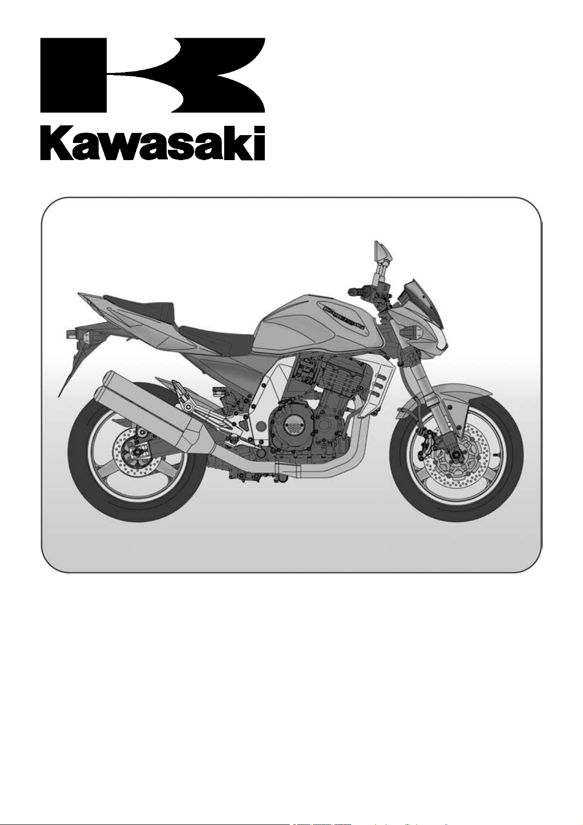
Battery Ground
Before completing any service on the motorcycle, disconnect t
from accidentally turning over. Disconnect the ground wire
(−) first and then the positive (+). When completed with the
servi
terminal of the battery then the negative (−) wire to the negative terminal.
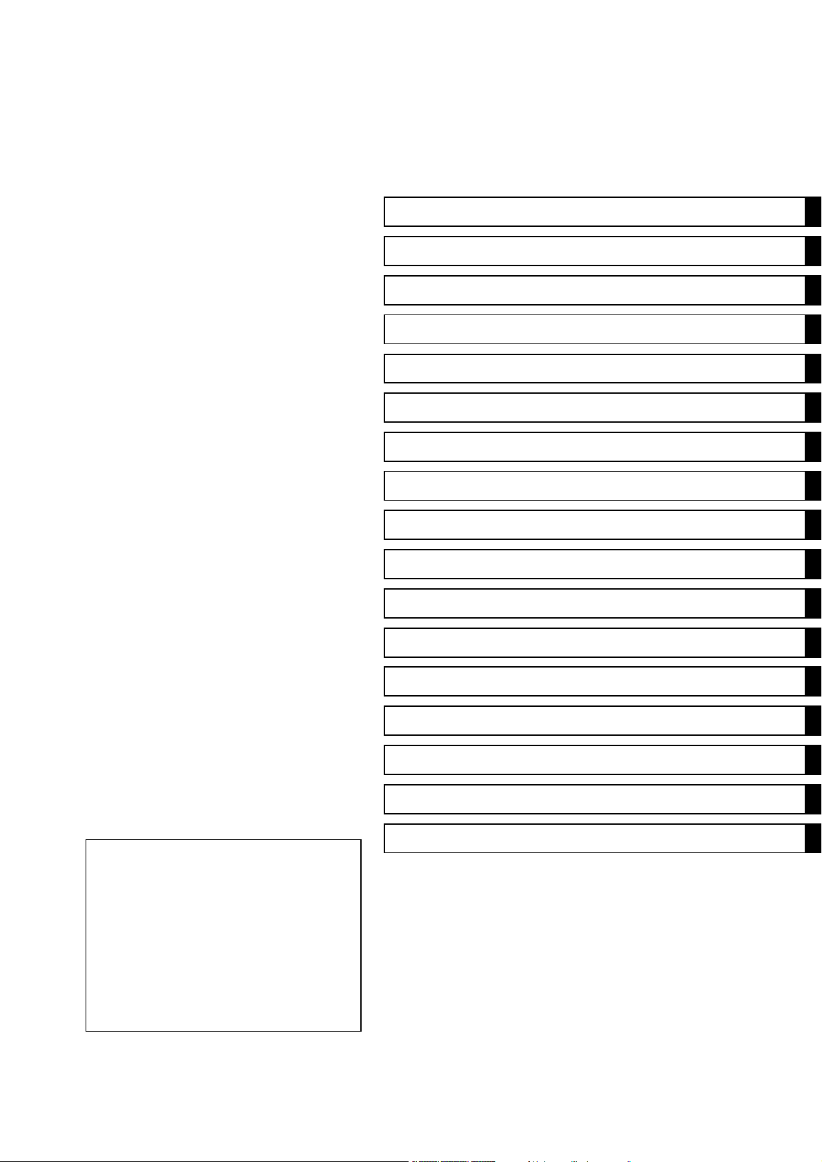
Edges of Parts
Lift large or heavy parts wearing gloves to prevent injury
from possible sharp edges on the parts.
ially note the following:
he battery wires from the battery to prevent the engine
ce, first connect the positive (+) wire to the positive (+)
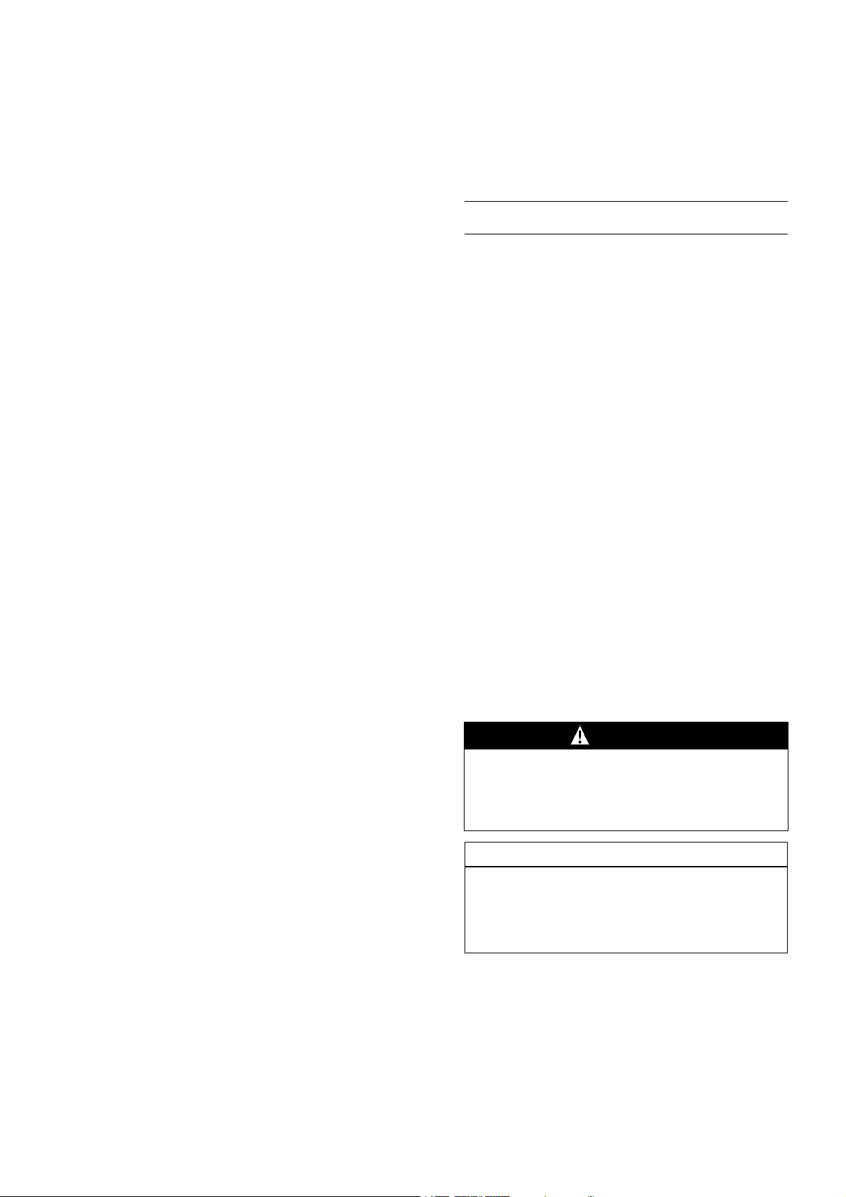
Solvent
Use a high flush point solvent when cleaning parts. High
flush point solvent should be used according to directions
of the solvent manufacturer.
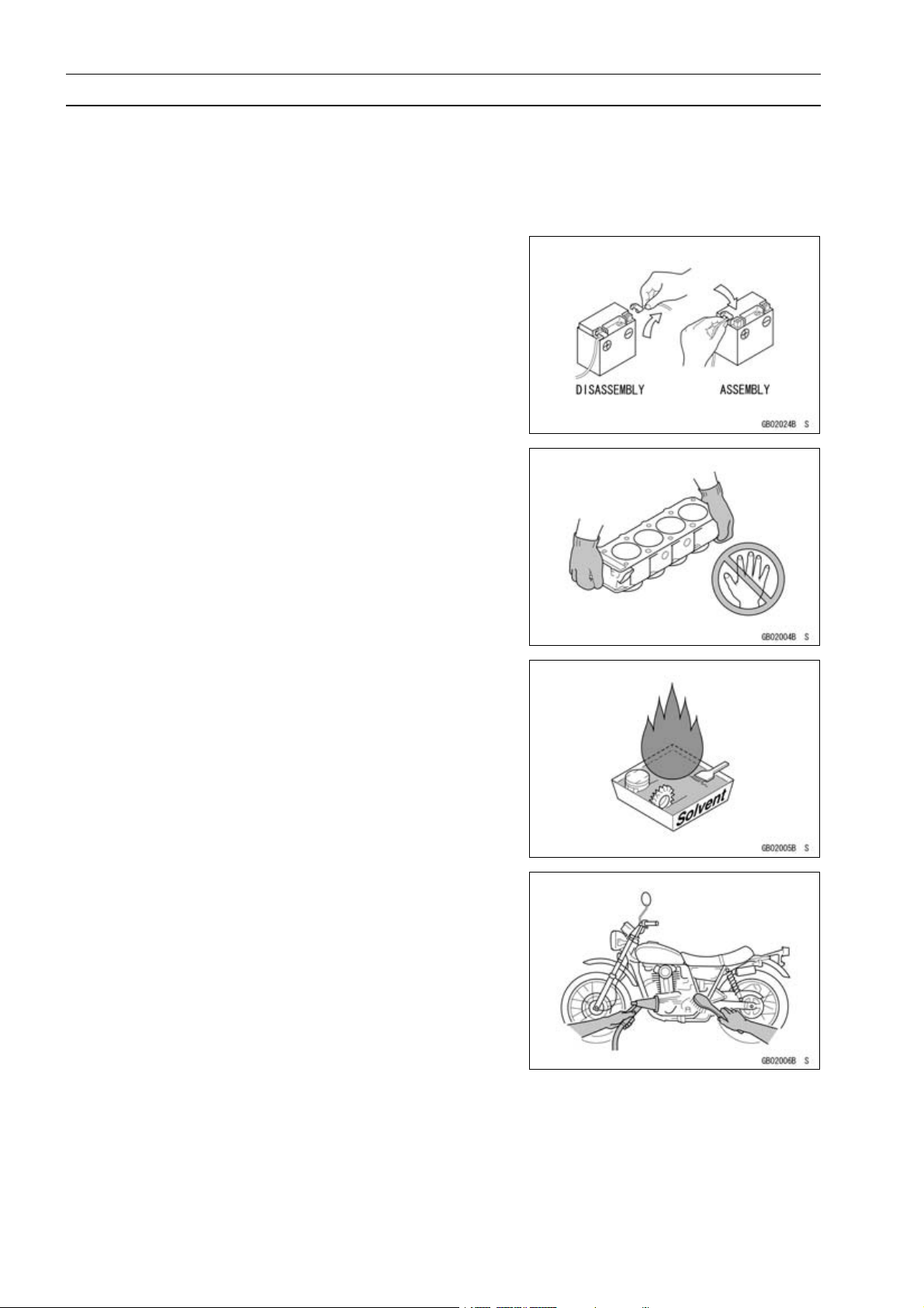
Cleaning vehicle before disassembly
Clean the vehicle thoroughly before disassembly. Dirt or
other foreign materials entering into sealed areas during vehicle disassembly can cause excessive wear and decrease
performance of the vehicle.
Before Servicing
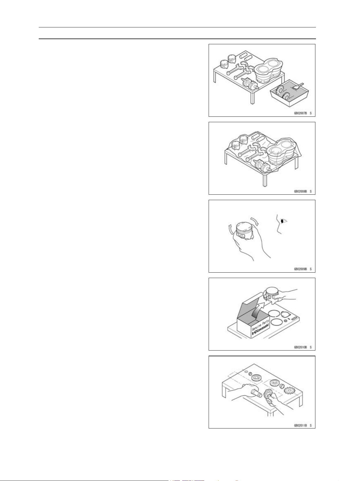
Arrangement and Cleaning of Removed Parts
Disassembled parts are easy to confuse. Arrange the
parts according to the order the parts were disassembled
and clean the parts in order prior to assembly.
Storage of Removed Parts
After all the parts including subassembly parts have been
cleaned, store the parts in a clean area. Put a clean cloth
or plastic sheet over the parts to protect from any foreign
materials that may collect before re-assembly.
GENERAL INFORMATION 1-3
Inspection
Reuse of worn or damaged parts may lead to serious accident. Visually inspect removed parts for corrosion, discoloration, or other damage. Refer to the appropriate sections
of this manual for service limits on individual parts. Replace
the parts if any damage has been found or if the part is beyond its service limit.
Replacement Parts
Replacement Parts must be KAWASAKI genuine or recommended by KAWASAKI. Gaskets, O rings, Oil seals,
Grease seals, circlips or cotter pins must be replaced with
new ones whenever disassembled.
Assembly Order
In most cases assembly order is the reverse of disassembly, however, if assembly order is provided in this Service
Manual, follow the procedures given.
1-4 GENERAL INFORMATION
Before Servicing
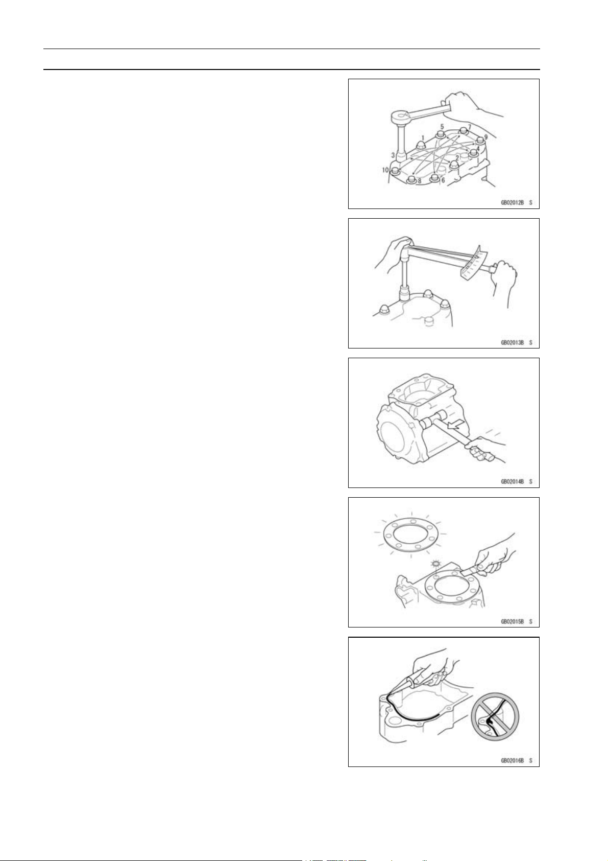
Tightening Sequence
Bolts, nuts, or screws must be tightened according to the
ied sequence to prevent case warpage or deformation
specif
which can lead to malfunction. If the specified tightening
sequence is not indicated, tighten the fasteners alternating
nally.
diago
Tightening Torque
Incorrect torque applied to a bolt, nut, or screw may
lead to serious damage. Tighten fasteners to the specified
torque using a good quality torque wrench.
Often, the tightening sequence is followed twice-initial
tightening and final tightening with torque wrench.
Force
Use common sense during disassembly and assembly,
excessive force can cause expensive or hard to repair damage. When necessary, remove screws that have a non
-permanent locking agent applied using an impact driver.
Use a plastic-faced mallet whenever tapping is necessary.
Gasket, Oring
Hardening, shrinkage, or damage of both gaskets and
grease seals after disassembly can reduce sealing performance. Remove old gaskets and clean the sealing surfaces
thoroughly so that no gasket material or other material remains. Install new gaskets and replace used grease seal
when re-assembling
Liquid Gasket, Locking Agent
For applications that require Liquid Gasket or a Locking
agent, clean the surfaces so that no oil residue remains before applying liquid gasket or locking agent. Do not apply
them excessively. Excessive application can clog oil passages and cause serious damage.
Before Servicing
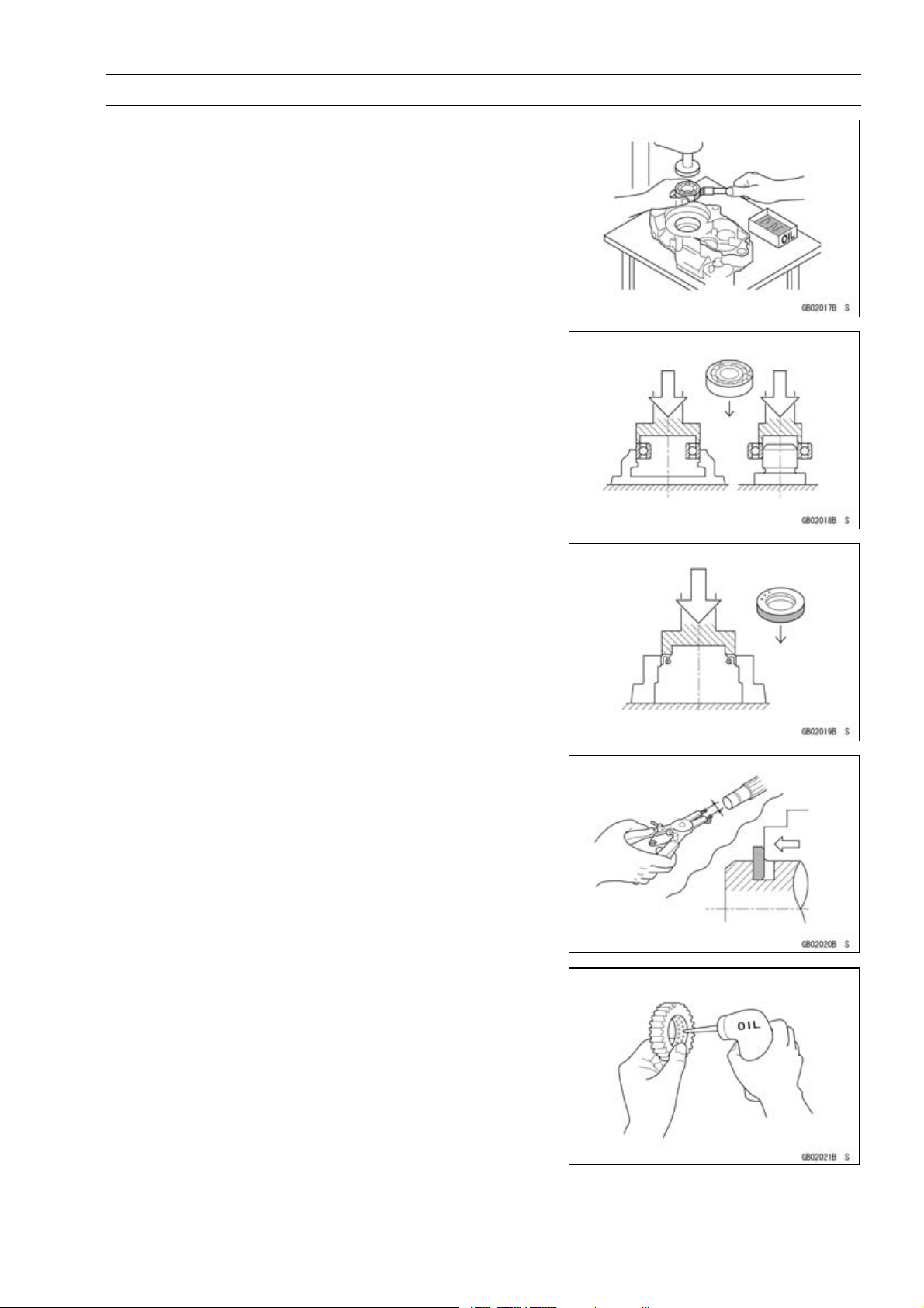
Press
For items such as bearings or oil seals that must be
pressed into place, apply small amount of oil to the contact area. Be sure to maintain proper alignment and use
smooth movements when installing.
Ball Bearing and Needle Bearing
Do not remove pressed ball or needle unless removal is
absolutely necessary. Replace with new ones whenever
removed. Press bearings with the manufacturer and size
marks facing out. Press the bearing into place by putting
pressure on the correct bearing race as shown.
Pressing the incorrect race can cause pressure between
the inner and outer race and result in bearing damage.
GENERAL INFORMATION 1-5
Oil Seal, Grease Seal
Do not remove pressed oil or grease seals unless removal
is necessary. Replace with new ones whenever removed.
Press new oil seals with manufacture and size marks facing
out. Make sure the seal is aligned properly when installing.
Circlips, Cotter Pins
Replace circlips or cotter pins t hat were removed with new
ones. Install the circlip with its sharp edge facing outward
and its chamfered side facing inward to prevent the clip from
being pushed out of its groove when loaded. Take care
not to open the clip excessively when installing to prevent
deformation.
Lubrication
It is important to lubricate rotating or sliding parts during
assembly to minimize wear during initial operation. Lubrication points are called out throughout this manual, apply
the specific oil or grease as specified.
1-6 GENERAL INFORMATION
Before Servicing
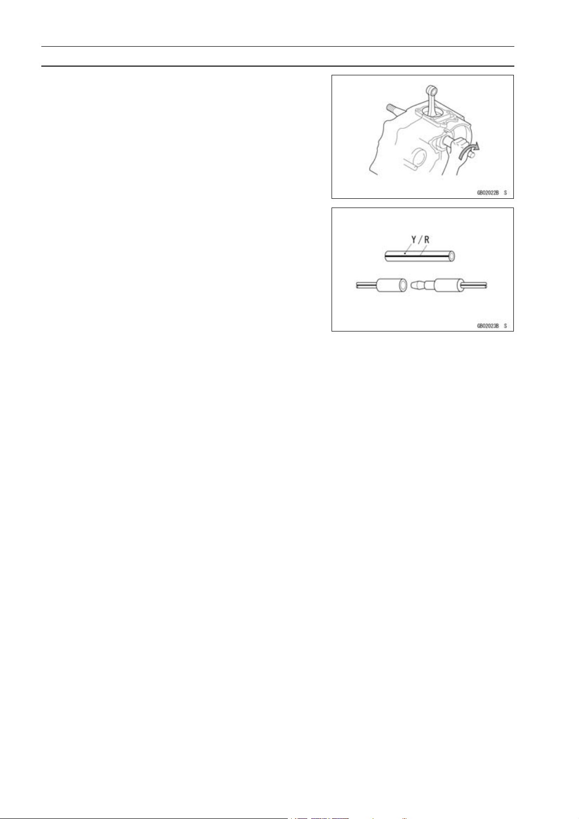
Direction of Engine Rotation
When rotating the crankshaft by hand, the free play
amount
tate the crankshaft to positive direction (clockwise viewed
from output side).
Electrical Wires
A two-color wire is identified first by the primary color and
then the stripe color. Unless instructed otherwise, electrical
wires must be connected to those of the same color.
of rotating direction will affect the adjustment. Ro-
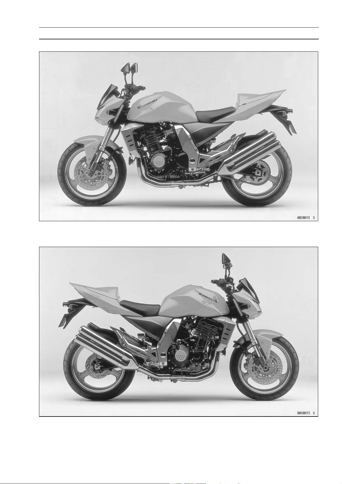
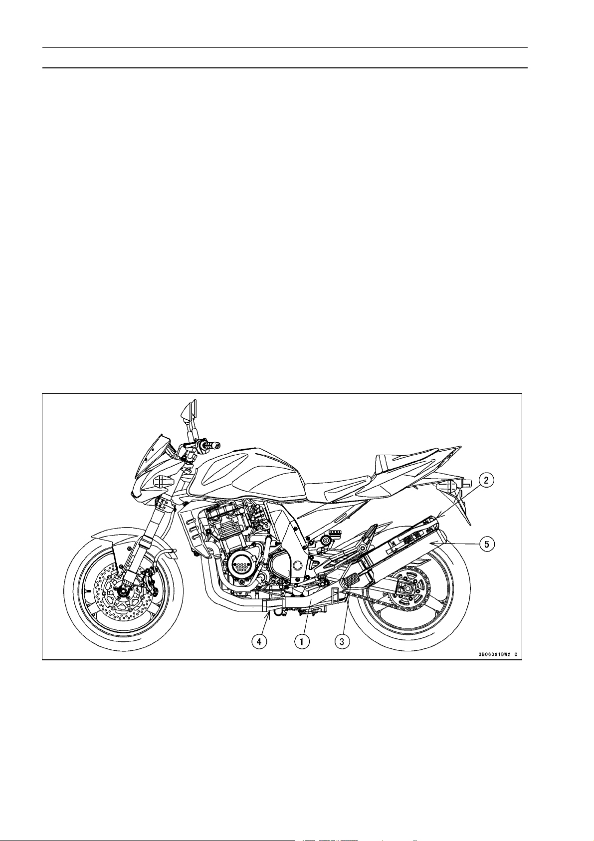
Model Identification
ZR1000–A1 Left Side View:
GENERAL INFORMATION 1-7
ZR1000–A1 Right Side View:

1-8 GENERAL INFORMATION
General Specifications
Items ZR1000–A1 ∼
Dimensions:
Overall length 2 080 mm (81.9 in.)
Overall width 770 mm (30.3 in.)
Overall height 1 055 mm (41.5 in.)
Wheelbase
Road clearance 145 mm (5.7 in.)
Seat height 820 mm (32.3 in.)
Dry mass 198 kg (410.1 lb)
Curb mass:
Fuel tank capacity
Performance:
Minimum turning radius
Engine:
Type
Cooling system Liquid-cooled
Bore and stroke
Displacement 953 mL (58.15 cu in.)
Compression ratio
Maximum horsepower 93.4 kW (127 PS) @10 000 r/min (rpm),
Maximum torque 95.6 N·m (9.7 kgf·m, 71 ft·lb) @8 000 r/min (rpm),
Carburetion system FI (Fuel Injection) Keihin TTK38 × 4
Starting system
Ignition system Battery and coil (transistorized)
Timing advance
Ignition timing From 10° BTDC @1 100 r/min (rpm)
Spark plug NGK CR9EK or ND U27ETR
Cylinder numbering method Left to right, 1-2-3-4
Firing order 1-2-4-3
Valve timing:
Inlet Open 38° BTDC
Exhaust Open 57° BBDC
Front
Rear 111 kg (244.8 lb)
Close 66° ABDC
Duration 284°
Close 31° ATDC
Duration
1 420 mm (55.9 in.)
110 kg (242.6 lb)
18 L (5.0 US gal.)
2.8 m (9.2 ft)
4-stroke, DOHC, 4-cylinder
77.2 × 50.9 mm (3.0 × 2.0 in.)
11.2
(MY, AU) 90.5 kW (123 PS) @10 000 r/min (rpm)
(HR) 78.2 kW (106 PS) @10 000 r/min (rpm)
(US)---
(MY, AU) 92.7 N ·m (9.4 kgf·m, 68 ft·lb) @8 000 r/min (rpm)
(HR) 86.3 N·m (8.8 kgf·m, 64 ft·lb) @7 500 r/min (rpm)
(US)---
Electric starter
Electronically advanced(digital igniter)
to 36° BTDC @7 500 r/min (rpm)
268°

General Specifications
Items ZR1000–A1 ∼
Lubrication system
Engine oil:
Type API SE, SF or SG
Viscosity SAE10W-40
Capacity 3.8 L (4.0 US qt)
Drive Train:
Primary reduction system:
Type Gear
Reduction ratio 1.714 (84/49)
Clutch type Wet m ulti disc
Transmission:
Type
Gear ratios:
1st 2.571 (36/14)
2nd 1.941 (33/17)
3rd 1.555 (28/18)
4th 1.333 (28/21)
5th
6th
Final drive system:
Type Chain drive
Reduction ratio 2.625 (42/16)
Overall drive ratio 4.929 @Top gear
Frame:
Type Tubular, diamond
Caster (rake angle) 24°
Trail 101 mm (4.0 in.)
Front tire: Type Tubeless
Size 120/70 ZR17 M /C ( 58W)
Rear tire: Type Tubeless
Size 190/50 ZR17 M /C ( 73W)
Front suspension:
Type Telescopic fork (upside-down)
Wheel travel 120 mm (4.7 in.)
Rear suspension:
Type Swingarm (uni-trak)
Wheel travel
Brake Type: Front Dual discs
Rear
Electrical Equipment:
Battery 12 V 8 Ah
Headlight: Type Semi-sealed beam
Bulb
Forced
API SH or SJ with JASO MA
6-s
.200 (24/20)
1
1.095 (23/21)
138 mm (5.4 in.)
Single disc
12 V 55 W × 2/55 W (Hi/Lo)
lubrication (wet sump with cooler)
peed, constant mesh, return shift
GENERAL INFORMATION 1-9

1-10 GENERAL INFORMATION
General Specifications
Items ZR1000–A1 ∼
Tail/brake light 12 V 0.5/3.8 W (LED)
(US, CA, Cal) 12 V 0.5/5W (LED)
Alternator: Type
Rated output 24 A/ 14 V @5 000 r/min (rpm)
Specifications are subject to change without notice, and may not apply to every country.
(AU): Australia Model
(US): U.S.A. Model
(CA): Canada Model
(Cal): C alifornia M odel
(MY): Malaysia Model
(HR): with Honeycomb Catalytic Converter Model (Restricted model)
Three-phase AC
GENERAL INFORMATION 1-11
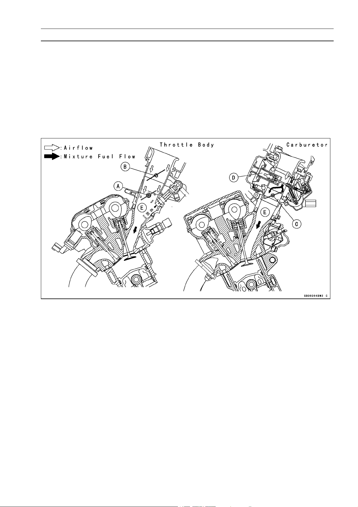
Technical Information – Air Inlet System
Subthrottle Control System
The ZR 1000–A1 ∼ employs large bore throttle bodies to increase power output. However, sudden
changes in throttle opening can cause hesitation and jerky throttle response with a single butterfly
valve in a large bore. Therefore two throttle valves are placed in each i nlet tract, the main throttle
valve located closest to the cylinder and a subthrottle valve placed further up the inlet tract. The main
throttle valve is operated by the rider when the throttle grip is turned clockwise or counterclockwise,
while the subthrottle valve is operated by a stepping motor controlled by the ECU. The subthrottle
valve automatically adjusts air inlet to more precisely match engine demand, so that when the main
throttle is opened quickly there is no hesitation or j erky response.
The subthrottle valves allow the fuel injection system to provide smooth t hrottle response, similar to
that of a constant velocity carburetor, no matter how quickly the throttle is opened.
A. Main Throttle Valve
B. Subthrottle Valve
C. Throttle Valve
D. Vacuum Piston
E. Inlet Air
1-12 GENERAL INFORMATION
Technical Information – Air Inlet System
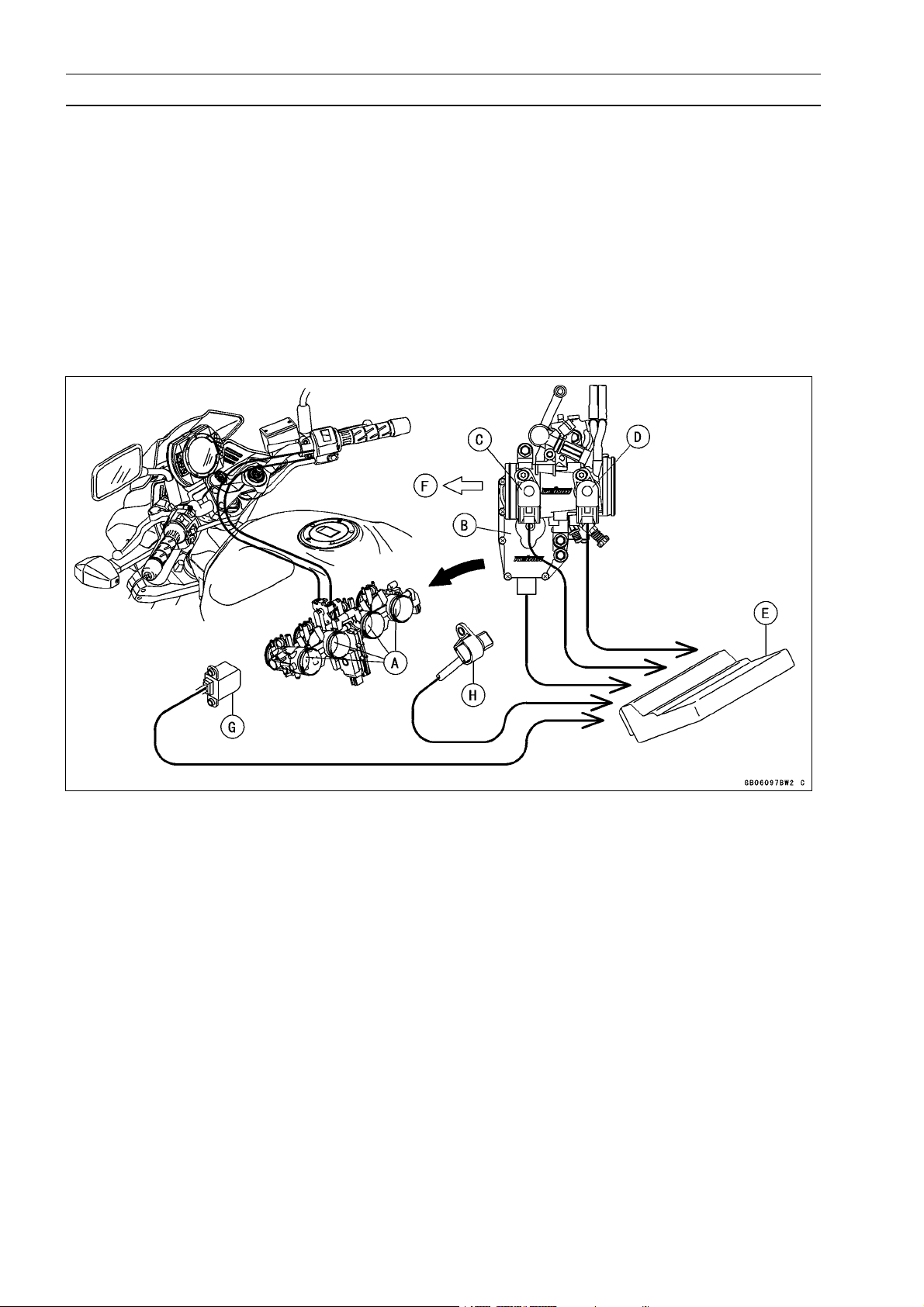
Operation
The subthrottle control system consists of the subthrottle valve, subthrottle valve actuator with a
ng motor built in it, ECU, and subthrottle sensor. The subthrottle valve is built in the each throttle
steppi
body.
The subthrottle control system operates on the signal supplied from the ECU. The open/close operation o
to change the current direction into the motor of the subthrottle valve actuator.
the EC
from fully closed position to fully opened position. The ECU memorizes these positions and turns
back t
f the subthrottle valve is performed by the subthrottle actuator which is controlled by the ECU
The subthrottle sensor detects the subthrottle valve actuator movement by measuring voltage and
U determines the subthrottle valve angle based on the operation map.
When turning the ignition switch ON, every time the ECU automatically drives the subthrottle valve
he subthrottle valve to the original point to confirm the subthrottle valve idling voltage.
bthrottle Valves
A. Su
B. Subthrottle Valve Actuator
C. Subthrottle Sensor
ain Throttle Sensor
D.M
U (Electric Control Unit)
E. EC
F. Air Cleaner Side
G. Crankshaft Sensor
peed Sensor
H.S

GENERAL INFORMATION 1-13
Technical Informatio n – New Ignition Interlock Sidestand
Outline
The New Ignition Interlock Sidestand System applied to ZR1000–A1 models that cannot function if
gears are engaged and/or the sidestand is not lifted upward even though clutch lever pulled in, which
differs from the traditional one. Refer to the tables below as to the engine starts and/or the driving at
each condition.
New Ignition Interlock Sidestand System
Side Stand Gear Position Clutch Lever Engine Start Engine Run
A Up Neutral Released Starts C ontinue running
B Up Neutral Pulled in Starts Continue running
C Up In Gear Released Doesn’t start Continue running
D Up In Gear Pulled in Starts Continue running
E Down Neutral Released Starts Continue running
F Down Neutral Pulled in Starts Continue running
G Down In Gear Released Doesn’t start Stops
H Down In Gear Pulled in Doesn’t start Stops
Current Ignition Interlock Sidestand System
Side Stand Gear Position Clutch Lever Engine S tart Engine Run
A Up Neutral Released Starts Continue running
B Up Neutral Pulled in Starts Continue running
C Up In G ear Released Doesn’t start Continue running
D Up In G ear Pul led in Starts Continue running
E Down Neutral Released Starts Continue running
F Down Neutral Pulled in Starts Continue running
G Down In Gear Released Doesn’t start Stops
H Down In Gear Pulled in Start Continue running
1-14 GENERAL INFORMATION
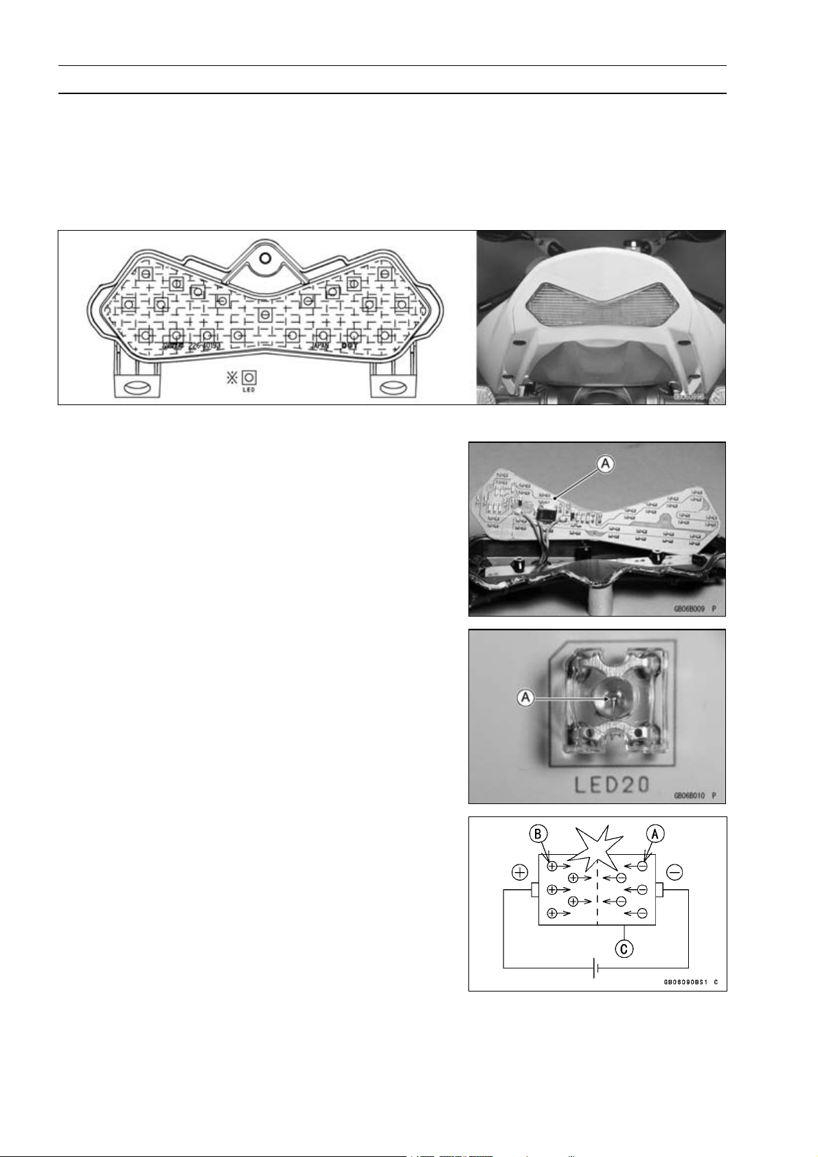
Technical Information – Tail/Brake Lights Employing LED
Outline
This model employs a tail/brake light containing 21 Light Emitting Diodes (LED). The LED emits
lumino
(more than 5 times longer), uses lower voltage, expends lower wattage (approx.1/5), and is quicker
responsing.
Due Position of LED Installation
us beams over a longer life span than those emitted from a traditional electric heated bulb
esistors, the diodes, and the Zener diodes are
The r
mounted in the electronic circuits [A] of the LED, which
supplies the steady current and voltage to the light.
Light Emitting Diode (LED)
The Light Emitting Diode (LED) [A] is an element of semiconductor diode that converts applied voltage to light.
The LED emits luminous beams by the collision of negative charge electrons [A] and positive charge holes [B] when
applied the forward voltage and current to the PN junction
diode [C].

GENERAL INFORMATION 1-15
Technical Information – Tail/Brake Lights Employing LED
The emitting color differs according to the materials of
semi-conductors.
Materials of Semi-Conductor and Emitting Color
Materials of Semi-Conductor Emitting Color
GaAsP
GaAlAs
GaP Gree
GaN Blue
,
Red
n
Ga: Gallium
As: Arsenic
P: Phosphorus
N: Nitrogen
Al: Aluminum
1-16 GENERAL INFORMATION
Technical Information - KLEEN (KAWASAKI LOW EXHAUST EMISSION SYSTEM)
Since the emission regulations become more severe, Kawasaki has adopted a type of simplified
KLEEN, which have no catalyst protection system, according to each regulation of different countries.
The muf
not use leaded gasoline and do not coast with the ignition system OFF. Running the engine without
ignition damages catalyst.
Refer t
(theory, maintenance, and handling precautions), including the secondary air injection system.
Honeycomb Type Catalytic Converter
The converter is a three-way catalytic converter, and its surface is covered with alumina upon which
○
platinum and rhodium are applied, and has a cylindrical metalic honeycomb structure made by bend-
ing a corrugated sheet and a flat sheet of stainless steel into a spiral of increasing diameter. The
honeycomb structure is convenient for the catalytic converter because it has a large surface area
but small size to react effectively and has low exhaust resistance. In addition, its inherent strength
helps resist vibration, and has simple structure welded directly on the silencer.
Generally, the temperature of the exhaust gas must be higher than activation temperature, so the
○
converters are installed in the exhaust manifold rear end where the temperature of exhaust gas is
still high. And, the converters will be activated even under low load conditions.
After t he exhasut gas is diluted with the secondary air injection, the catalytic converter works well
○
because of rich oxygen to reduce CO, HC, and NO
emission within regulation.
This type of converter works more efficiently as a three-way catalytic converter to reduce CO, HC,
○
and NO
fler with built-in catalyst has the same durability as the conventional muffller, however, do
o the ZX900E Service Manual (Part No. 99924-1255) for more information about the KLEEN
x. A ccordingly, we can keep the exhaust gas
x than the pipe type catalytic converter because of its more and denser catalysts.
1. Manifold
2. Silencer
3. Honeycomb Type Catalyst
4. Mark for Manifold
5. Mark for Silencer
Unit Conversion Table
GENERAL INFORMATION 1-17
Prefixes for Units:
Prefix Symbol Power
mega M × 1 000 000
kilo k × 1 000
centi c ×0.01
milli m ×0.001
micro µ × 0.000001
Units of Mass:
kg ×2.205=lb
g × 0.03527 = oz
Units of Volume:
L × 0.2642 = gal (US)
L × 0.2200 =
L × 1.057 = qt (US)
L × 0.8799 = qt (imp)
L × 2.113 = pint (US)
L × 1.816 = pint (imp)
mL × 0.03381 =
mL × 0.02816 = oz (imp)
mL × 0.06102 = cu in
gal (imp)
oz (US)
Units of Length:
km × 0.6214 = mile
m × 3.281 = ft
mm × 0.03937 = in
Units of Torque:
N·m × 0.1020 = kgf·m
N·m × 0.7376 = ft·lb
N·m × 8.851 = in·lb
kgf·m × 9.807 = N·m
kgf·m
kgf·m × 86.80 = in·lb
× 7.233 =
ft·lb
Units of Pressure:
kPa × 0.01020 = kgf/cm²
kPa × 0.1450 = psi
kPa × 0.7501 = cm Hg
kgf/cm²
kgf/cm² × 14.22 = psi
cmHg×1.333=kPa
× 98.07 = kPa
Units of Speed:
km/h × 0.6214 = mph
Units of Force:
N × 0.1020 = kg
N × 0.2248 = lb
kg ×9.807=N
kg ×2.205=lb
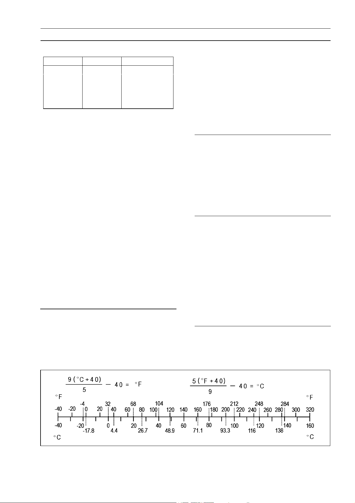
Units of Temperature:
Units of Power:
kW ×1.360=PS
kW ×1.341=HP
PS × 0.7355 = kW
PS
× 0.9863 = HP


PERIODIC MAINTENANCE 2-1
Periodic Maintenance
Table of Con tents
Periodic Maintenance Chart .............. 2-2
Torque and Locking Agent................. 2-4
Specifications .................................... 2-9
Special Tools ..................................... 2-11
Periodic Maintenance Procedures..... 2-12
Fuel System (DFI)........................... 2-12
Fuel Hose and Connection
Inspection .................................. 2-12
Throttle Control System
Inspection .................................. 2-13
Idle Speed Inspection .................. 2-14
Idle Speed Adjustment................. 2-14
Engine Vacuum Synchronization
Inspection .................................. 2-15
Air Cleaner Element Cleaning...... 2-19
Evaporative Emission Control
System Inspection (CAL) .......... 2-20
Cooling System............................... 2-21
Radiator Hose and Connection
Inspection .................................. 2-21
Coolant Change ........................... 2-21
Engine Top End .............................. 2-23
Air Suction Valve Inspection ........ 2-23
Valve Clearance Inspection ......... 2-24
Valve Clearance Adjustment........ 2-25
Clutch.............................................. 2-28
Clutch Adjust Inspection .............. 2-28
Engine Lubrication System ............. 2-29
Engine Oil C hange....................... 2-29
Oil Filter Change .......................... 2-29
Wheels/Tires................................... 2-30
Tire Inspection ............................. 2-30
Air Pressure
Inspection/Adjustment............... 2-31
Final Drive....................................... 2-31
Drive Chain Slack Inspection ....... 2-31
2
Drive Chain Slack Adjustment ..... 2-31
Wheel Alignment
Inspection/Adjustment............... 2-32
Drive Chain Wear Inspection ....... 2-32
Drive Chain Lubrication................ 2-33
Brakes............................................. 2-34
Brake Pad Wear Inspection ......... 2-34
Rear Brake Light Switch
Inspection/Adjustment............... 2-34
Caliper Fluid Seal Damage .......... 2-35
Caliper Dust Seal/Friction Boot
Damage..................................... 2-35
Master Cylinder Inspection (Visual
Inspection)................................. 2-36
Level Inspection ........................... 2-37
Brake Fluid Change ..................... 2-37
Brake Line Bleeding..................... 2-39
Brake Hoses and Connections
Inspection .................................. 2-41
Suspension..................................... 2-42
Front Fork Oil Leak Check ........... 2-42
Rear Shock Absorber Oil Leak
Check ........................................ 2-42
Swingarm Pivot Lubrication ......... 2-42
Uni-trak Linkage Lubrication ........ 2-42
Steering .......................................... 2-43
Steering Inspection ...................... 2-43
Steering Adjustment..................... 2-43
Stem Bearing Lubrication............. 2-44
Electrical System ............................ 2-44
Spark Plug Cleaning and
Inspection .................................. 2-44
General Lubrication ........................ 2-47
Lubrication ................................... 2-47
Nut, Bolt, and Fastener Tightness .. 2-48
Tightness Inspection.................... 2-48

2-2 PERIODIC MAINTENANCE
Periodic Maintenance Chart
The scheduled maintenance m ust be done in accordance with this chart to keep the motorcycle in
good running condition. The initial maintenance is vitally important and must not be neglected.
FREQUENCY Whichever 1 000 km *ODOMETER
READING
18 000 km
(12 000 mile)
24 000 km
(15 000 mile)
30 000 km
(20 000 mile)
36 000 km
(24 000 mile)
•
OPERATION
Spark plug (e) - clean and gap †
Valve clearance (e) - inspect †
Air suction valve (e) - inspect †
Air cleaner element (e) - clean† #
Throttle control system (e) - inspect †
Idle speed (e) - inspect †
Engine vacuum synchronization (e) inspect †
comes (600 mile)
first
→ (4 000 mile)
↓ 12 000 km
Every
6 000 km
( 7 500 mile)
• • • • • •
• • • • • •
• • •
• • • • • • •
• • • •
• • •
Fuel hoses, connections - inspect †
Engine oil - change # year
Oil filter - replace
Evaporative emission control system (e)
(CAL) - inspect †
Drive chain wear - inspect †#
Brake pad wear - inspect †#
Brake light switch - inspect †
Steering - inspect †
Rear shock absorber oil leak - inspect †
Front fork oil leak - inspect †
Tire wear - inspect †
Swingarm pivot, Uni-trak linkage lubricate
General lubrication - perform
Nut, bolt, and fastener tightness - inspect
†
Drive chain - lubricate # 600 km
Drive chain slack - inspect †# 1000 km
Brake hoses, connections - inspect †
Brake fluid level - inspect † month
• • • • • •
• • • •
• • • •
• • • • • • •
• • • • • •
• • • • • •
• • • • • • •
• • • • • • •
• • •
• • •
• • • • • •
• • •
• • •
• • • •
• • • • • •
• • • • • • •

Periodic Maintenance Chart
FREQUENCY Whichever 1 000 km *ODOMETER
comes (600 mile)
first 6 000 km
↓ 12 000 km
OPERATION Every
Clutch-adjust †
Radiator hoses, c onnections - inspect †
Brake fluid - change
rake master cylinder cup and dust seal
B
- replace
2 years
4 years
PERIODIC MAINTENANCE 2-3
READING
→ (4 000 mile)
( 7 500 mile)
18 000 km
(12 000 mile)
24 000 km
(15 000 mile)
30 000 km
(20 000 mile)
36 000 km
(24 000 mile)
• • • • • • •
•
•
Coolant - change 2 years
Caliper piston seal and dust seal replace
Steering stem bearing - lubricate
# : Service more frequently when operating in severe conditions; dusty, wet, muddy, high speed,
or frequent starting / stopping.
* : For higher odometer readings, repeat at the frequency interval established here.
† : Replace, add, adjust, clean, or torque if necessary.
Throttle control system inspection: Inspection of throttle grip play and main throttle bore cleanliness
(CAL): California Model only
(e): Emission Related Items
4 years
2 years
•
•

2-4 PERIODIC MAINTENANCE
Torque and Locking Agent
The following tables list the tightening torque
for the major fasteners requiring use of a non
-perma
Letter
MO: Apply molybdenum disulfide grease oil
nent locking agent or liquid gasket.
s used in the “Remarks” column mean:
L: Apply a non-permanent locking agent to
the threads.
G: Apply
solution.
EO: Apply
face.
S: Tighten the fasteners following the speci-
fied
SS: Apply silicone sealant.
Si: Apply silicone grease (ex. PBC grease).
R: Rep
AL: Tighten the two clamp bolts alternately
two times to ensure even tightening
tor
grease to the threads.
oil to the threads and seating sur-
sequence.
lacement parts
que.
The table on the right lists the basic torque
for the bolts and nuts, which are determined
by thei
bolts and nuts that are not listed in the table
below according to their thread diameter. All of
the ti
threads that have been cleaned with solvent.
r thread diameter. Use this table for the
ghtening torque values are for use with dry
Basic Torque for General Fasteners
Threads Torque
dia. (mm) N·m kgf·m ft·lb
5 3.4 ∼ 4.9 0.35 ∼ 0.50 30 ∼ 43 in·lb
6 5.9 ∼ 7.8 0.60 ∼ 0.80 52 ∼ 69 in·lb
8 14 ∼19 1.4 ∼1.9 10.0 ∼ 13.5
10 25 ∼ 34 2.6 ∼ 3.5 19.0 ∼ 25
12 44 ∼ 61 4.5 ∼ 6.2 33 ∼ 45
14 73 ∼ 98 7.4 ∼ 10.0 54 ∼ 72
16 115 ∼ 155 11 .5 ∼ 16.0 83 ∼ 11 5
18 165 ∼ 225 17.0 ∼ 23.0 125 ∼ 165
20 225 ∼ 325 23 ∼ 33 165 ∼ 240
Fastener
Fuel System:
Inlet air pressure sensor bolt 12 1.2 104 in·lb
Water temperature sensor 25 2.5 18
Vehicle downsensor bolts 2 0.2 17 in·lb
Cam shaft position sensor bolt
Cam shaft position sensor rotor bolt 12 1.2 104 in·lb L
Throttle cable plate bolt 6 0.6 52 in·lb
Throttle body cover bolts 7 0.7 61 in·lb
Throttle body assy holder clamp bolts 2 0.2 17 in·lb
Choke link holder screws 2.1 0.21 18 in·lb
Delivery pipe screws 3.4 0.35 30 in·lb
Bypass screws 0.2 0.02 1.7 in·lb
Air cleaner duct holder screws 3.8 0.39 34 in·lb
Air cleaner housing mounting bolts 9.8 1.0 87 in·lb
Air cleaner duct clamp bolts 2 0.2 17 in·lb
Air cleaner housing screws 1.2 0.12 10 in·lb
Air cleaner housing tapping screws 1.2 0.12 10 in·lb
Speed sensor bolt 6.9 0.7 62 in·lb L
Fuel pump bolts 9.8 1.0 87 in·lb
Fuel level sensor bolts 6.9 0.7 62 in·lb
Cooling System:
Radiator hose clamp screws 2 0.2 17 in·lb
Thermostat air bleeder bolt 7.8 0.80 69 in·lb
Radiator fan bolts 8.3 0.85 74 in·lb
Water pump impeller bolt 10 1.0 87 in·lb
Water pump cover bolts 11 1.1 95 in·lb
N·m kgf·m ft·lb
12 1.2 104 in·lb
Torque
Remarks
S, L

Torque and Locking Agent
PERIODIC MAINTENANCE 2-5
Fastener
Water p
Water pipe bolts 11 1.1 95 in·lb in/outlet
Therm
Thermostat bracket bolt 7 0.7 61 in·lb
Radi
Radiator lower bolts 7 0.7 61 in·lb
Rad
Coolant reserve tank screws 7 0.7 61 in·lb
Radiator fan switch 18 1.
Water temperature sensor 25 2.5 18
ngine Top End:
E
Air suction valve cover bolts 10 1.0 87 in·lb
Cylinder head cover bolts
Camshaft cap bolts (L=45 mm) 12 1.2 104 in·lb
Camshaft cap bolts (L=40 mm)
Cylinder head bolts (M10 new bolts) 54 5.5 40 S, EO
Cylinder head bolts (M10 used bolts) 49 5.0 36 S, EO
Cylinder head bolts (M6) 12 1.2 104 in·lb S
Cylinder head jacket plugs
Throttle body holder bolts 13 1.3 113 in·lb
Throttle body holder clamp screws 2.0 0.2 17 in·lb
Camshaft sensor bolt 12 1.2 104 in·lb
Camshaft sensor rotor bolt
Front camshaft chain guide bolt (upper) 25 2.5 18
Front camshaft chain guide bolt (lower)
Rear camshaft chain guide bolt 25 2.5 18
Camshaft chain tensioner mounting bolts
Camshaft chain tensioner cap bolt 28 2.9 21
Spark plugs
Coolant drain plug (Cylinder) 10 1.0 87 in·lb
Exhaust pipe manifold holder nuts
Muffler body clamp bolts 17 1.7 12
Muffler body mounting bolts
Crankshaft sensor cover bolts 11 1.1 95 in·lb
Clutch:
Clutch lever clamp bolts 7.9 0.8 69 in·lb S
Clutch cover bolts (L=32 mm)
Clutch cover bolts (L=45 mm) 11 1.1 95 in·lb
Clutch cover bolts (L=30 mm)
Clutch cover bolts 11 1.1 95 in·lb
Oil filler plug
Clutch spring bolts 8.8 0.9 78 in·lb
Clutch hub nut
ump drain bolt
ostat housing ground bolt
ator upper bolts
iator screen bolt
N·m kgf·m ft·lb
11 1.1 95 in·l
7 0.7 61 in·
7 0.7 61 in
7 0.7 61 i
10 1.0 87 in·lb
12 1.2 104 in·lb
22 2.2 16 L
12 1.2 104 in·lb L
12 1.2 104 in·lb
11 1.1 95 in·lb
13 1.3 113 in·lb
17 1.7 12
34 3.5 25
11 1.1 95 in·lb
11 1.1 95 in·lb
1.5 0.15 13 in·lb
135 14 100 R
Torque
8
Remarks
b
lb
·lb
n·lb
13
(Washer)
(Washer)

2-6 PERIODIC MAINTENANCE
Torque and Locking Agent
Fastener
Engine
Oil filler plug 1.5 0.15 13 in·lb
Engin
Oil filter (cartridge type, P/No.16097–1070) 26 2.7 20 R, EO
Oil filter (cartridge type, P/No.16097–0002) 31 3.2 23 R, EO
Oil cooler mounting bolt 76 7.8 56 EO
Oil pan bolts 11 1.1 95 i
Oil pipe holder bolts 13 1.3 113 in·lb L
Oil pressure relief valve 15 1.
Oil pressure switch 15 1.5 11 SS
Oil pressure switch terminal bolt 1
Water pump cover bolts 11 1.1 95 in·lb
Impeller bolt 10 1.0 87 in·lb
Coolant drain plug (water pump) 11 1.1 95 in·lb
Water hose clamp screws 2.0 0.2 17 in·lb
Oil passage plugs 20 2.0 14.5 L
Engine Removal/Installation:
Adjusting collar locknut 49 5.0 36 in·lb S
Engine mounting bolts and nuts 44 4.5 32
Front engine bracket bolts 44 4.5 32 S
Rear engine bracket bolts 25 2.5 18
Crankshaft/Transmission:
Breather plate bolts 10 1.0 87 in·lb L
Crankcase bolts (M9, L=81 mm) 42 4.3 31 MO,S
Crankcase bolts (M9, L=95 mm)
Crankcase bolts (M8) 27 2.8 20 S
Crankcase bolts (M7)
Crankcase bolts (M6) 12 1.2 104 in·lb S
Starter motor clutch bolts
Oil pipe holder bolts 13 1.3 113 in·lb L
Shift drum bearing holder bolt
Shift drum bearing holder screw 5.4 0.55 48 in·lb L
Connecting rod big end nuts
Crankshaft position rotor bolt 40 4.0 29
Oil pressure switch
Oil pressure switch terminal bolt 1.5 0.15 13 in·lb
Oil passage plugs
Crankshaft sensor cover bolts 11 1.1 95 in·lb
Shift pedal mounting bolt
Gear positioning lever bolt 12 1.2 104 in·lb
Shift shaft return spring pin
Shift drum cam holder bolt 12 1.2 104 in·lb L
Footpeg bracket bolts 34 3.5 25 L
Shift lever bolt 6.9 0.7 61 in·lb
Tie-rod locknuts 6.9 0.7 61 in·lb
Neutral switch 15 1.5 11
Lubrication:
e drain plug
N·m kgf·m ft·lb
20 2.0 14.5
.5
49 5.0 36
20 2.0 14.5
12 1.2 104 in·lb L
13 1.3 113 in·lb L
see the text ← ← ←
15 1.5 11
20 2.0 14.5 L
34 3.5 25 L
29 3.0 22 L
Torque
5
.15
0
n·lb
11 L
3in·lb
1
Remarks
MO,S
S
S
S
SS

Torque and Locking Agent
PERIODIC MAINTENANCE 2-7
Fastener
Wheels/Tires:
Front axle clamp bolt 34 3.5 25
axle
Front
Rear axle nut 127 13 94
l Drive:
Fina
Engine sprocket nut 127 13 94 MO
ine sprocket cover bolts
Eng
Engine sprocket cover damper bolt 6.9 0.7 61 in·lb L
ar sprocket nuts
Re
Speed sensor bolt 6.9 0.7 61 in·lb L
rakes:
B
Bleed valves 7.8 0.80 69 in·lb
Front brake hose joint bracket bolts 6.9 0.7 61
Brake hose banjo bolts 25 2.5 18
Brake lever pivot bolt 1.0 0.10 9in·lb
Brake lever pivot bolt locknut 5.9 0.60 52 in·lb
Front brake reservoir cap screws 1.5 0.15 13 in·lb
Front brake light switch screws 1.2 0.12 11 i n ·l b
Front master cylinder clamp bolts 8.8 0.9 78 in·lb
Pad pin bolts (Front caliper) 17 1.7 12
Caliper mounting bolts (Front)
Caliper assembly bolts (Front) 22 2.2 16 L
Front brake disc mounting bolts 27 2.8 20 L
Rear brake disc mounting bolts 27 2.8 20 L
Caliper mounting bolts (Rear)
Rear master cylinder mounting bolts 25 2.5 18
Rear master cylinder push rod locknut 18 1.8 13
Suspension:
Front fork clamp bolts (Upper)
Front fork clamp bolts (Upper): ZR1000–A2 ∼ 13 1.3 113 in·lb
Front fork clamp bolts (Lower)
Front fork clamp bolts (Lower): ZR1000–A2 ∼ 30 3.1 22
Front fork top plugs
Piston rod nuts 20 2.0 15
Front fork bottom Allen bolts
Front axle clamp bolt 20 2.0 15
Rear shock absorber nuts (Upper and lower)
Swingarm pivot shaft nut 127 13 94
Swingarm pivot shaft locknut
Uni-trak
Rocker arm bolt 34 3.5 25
Tie-rod nuts 59 6.0 43
Steering:
Steering stem head bolt 108 11 80
Steering stem nut
Handlebar clamp bolts 25 2.5 18 S
N·m kgf·m ft·lb
127 13 94
9.8 1.0 87 i
59 6.
25 2.5 18
25 2.5 18
8.8 0.90 78 in·lb AL
20 2.0 15 AL
35 3.6 26
20 2.0 15
34 3.5 25
98 10 72
20 2.0 14.5
Torque
0
Remarks
n·lb
43
S

2-8 PERIODIC MAINTENANCE
Torque and Locking Agent
Fastener
Handle
Handlebar switch housing screws 3.4 0.35 30 in·lb
Frame
Footpeg holder bolts 34 3.5 25
Muffler mounting bolts 29 3.0 22
Side stand bolt 44 4.5 33
Side stand switch bolt 8.8 0.9 78 i
Windshield screws 0.35 ∼ 0.50 0.035 ∼ 3 ∼ 4in·lb
Front fender bolts 3.9 0.4 34.7 in·lb L
Electrical System:
Spark plugs 13 1.3 115 in·lb
Alternator rotor bolt 110 11 81
Stator coil bolts 11 1.1 95 in·lb
Alternator lead holding plate bolt 11 1.1 95 in·lb L
Engine ground cable terminal bolt 9.8 1.0 87 in·lb
Alternator cover bolts 11 1.1 95 in·lb
Crankshaft sensor cover bolts 11 1.1 95 in·lb
Crankshaft sensor bolts
Camshaft position sensor bolt 12 1.2 104 in·lb L
Timing rotor bolt 39 4.0 29
Starter motor mounting bolts 11 1.1 95 in·lb
Switch housing screws
Radiator fan switch 18 1.8 13
Water temperature sensor 25 2.5 18
Oil pressure switch 15 1.5 11 SS
Oil pressure switch terminal bolt
Neutral switch 15 1.5 11
Speed sensor bolt
Fuel level sensor bolts 6.9 0.7 62 in·lb
Front brake light switch screw 1.2 0.12 11 in·lb
Meter mounting screws 1.2 0.12 11 in·lb
Tail/brake light mounting screws
License plate light mounting screws 1.2 0.12 11 in·lb
Headlight mounting bolts 5.9 0.6 53 in·lb
Starter lockout switch screw - - - L
Starter motor clutch bolts
Starter relay cable terminal bolts 3.9 0.4 35 in·lb L
Regulator/rectifier bolts
Regulator/rectifier bracket bolts 6.9 0.7 62 in·lb
Speed sensor cover bolts
bar lower clamp nuts
:
N·m kgf·m ft·lb
34 3.5 25
5.9 0.6 53 in·lb
3.4 0.35 30 in·lb
1.5 0.15 13 in·lb
6.9 0.7 62 in·lb
1.2 0.12 11 in·lb
12 1.2 104 in·lb L
6.9 0.7 62 in·lb
6.9 0.7 62 in·lb L
Torque
0.050
Remarks
n·lb
SS
G

PERIODIC MAINTENANCE 2-9
Specifications
Item Standard Service Limit
Fuel System:
Throttle grip free play 2 ∼ 3 mm (0.08 ∼ 0.12 in.)
Idle speed 1 100 ± 50 r/min (rpm)
Bypass screws (turn out) 2 ± 1/4 (for reference)
Engine vacuum 32.7 ± 1.333 kPa (245 ± 10 mm Hg)
Air cleaner element
Cooling System:
Coolant:
Type (recommended) Permanent type of antifreeze
Color Green
Mixed ratio
Freezing point – 35°C (– 31°F)
Total amount 2.9 L (3.1 US qt)
Engine Top End:
Valve clearance
Inlet
Exhaust 0.22 ∼ 0.31 mm (0.0087 ∼ 0.0122 in.)
lutch:
C
Clutch lever free play 2 ∼ 3 mm (0.08 ∼ 0.12 in.) –––
Engine Lubrication System:
Engine Oil:
Type API SE, SF or SG
Viscosity SAE 10W-40
Capacity 3.1 L
Level Between upper and lower level lines
Tires:
Tread depth:
Front
BRIDGESTONE 3.4 mm (0.13 in.) 1 mm (0.04 in.)
r filter
Pape
Soft water 50%, Coolant 50%
0.15 ∼ 0.24 mm (0.0059 ∼ 0.0094 in.)
API SH or SJ with JASO MA
(3.3 US qt, when filter is not removed)
3.3 L
(3.5 US qt, when filter is removed)
3.8 L
(4.0 US qt, when engine is completely
disassembled and dry)
(after idling or running)
1.6 mm (0.063 in.)
(DE, AT, CH)
–––
Rear
BRIDGESTONE 5.8 mm (0.23 in.) Up to 130 km/h
(80 mph):
2 mm (0.08 in.)
Over 130 km/h
(80 mph):
3 mm (0.12 in.)

2-10 PERIODIC MAINTENANCE
Specifications
Item Standard Service Limit
Air pressure: (when cold)
Front
Rear Up to 180 kg (396 lb) load:
Final Drive:
Drivechainslack
Drive chain (20-link length) 317.5 ∼ 318.2 mm (12.50 ∼ 12.53 in.) 323 mm (12.7 in.)
Brakes:
Brake fluid:
Grade DOT4 –––
ke pad lining thickness:
Bra
Front 4 mm (0.16 in.) 1 mm (0.04 in.)
Rear
Brake l ight timing:
Front Pulled ON –––
Rear ON after about 10 mm (0.39 in.) of pedal
Electrical System:
Spark plug gap 0.7 ∼ 0.8 mm (0.028 ∼ 0.031 mm) –––
AT: Republic of Austria
CH: Swiss Confederation
DE: Federal Republic of Germany
Up to 180 kg (396 lb) l oad:
250 kPa (2.5 kgf/cm², 36 psi)
290 kPa (2.9 kgf/cm², 41 psi)
20 ∼ 30 mm (0.8 ∼ 1.2 in.)
5 mm (0.20 in.) 1 mm (0.04 in.)
travel
–––
–––
–––
–––

Special Tools
PERIODIC MAINTENANCE 2-11
Steering Stem Nut Wrench:
57001–1100
Jack:
57001–1238
Oil Filter Wrench:
57001–1249
Pilot Screw Adjuster, C:
57001–1292
Hand Tester:
57001–1394
Spark Plug Wrench (Owner ’s Tool):
92110–1132

2-12 PERIODIC MAINTENANCE
Periodic Maintenance Procedures
Fuel System (DFI)
Fuel Hose and Connection Inspection
The fuel hoses are designed to be used throughout the
○
motorcycle’s life without any maintenance, however, if the
motorcycle is not properly handled, the high pressure inside the fuel line can cause f uel to leak [A] or the hose
to burst. Remove the fuel tank (see Fuel System (DFI)
chapter) and check the fuel hoses.
Replace the hose if any fraying, cracks [B] or bulges [C]
are noticed.
Check that the hoses are routed according to Cable, Wire,
•
and Hose Routing section in the Appendix chapter.
Replace the hose if it has been sharply bent or kinked.
Hose Joints [A]
Pump Outlet Hose [B]
Pump Inlet Hose [C]
Front [D]
Insert the pump outlet hose joint [A] straight onto the de-
•
livery pipe [B] until the hose joint clicks [C].
Front [D]
Push and pull [A] the hose joint [B] back and forth more
•
than two times, and make sure it is locked and doesn’t
come off. When the hose j oint is correctly installed, it
should slide on the delivery pipe about 5 mm (0.20 in.).
If it does not slide, reinstall the hose joint.
WARNING
Make sure the hose joint is installed correctly on the
delivery pipe by sliding the joint, or the fuel could
leak.
Check that the inlet hose [A] is onto the pipe fully and the
•
plate clamps [B] are installed beyond the raised rib [C].
1 ∼ 2 mm (0.039 ∼ 0.079 in.) [D]

Periodic Maintenance Procedures
Throttle Control System Inspection
Throttle Grip Play Inspection
Check the throttle grip free play [A].
•
If the free play is incorrect, adjust the throttle cable (see
below).
Throttle Grip Free Play
Standard: 2 ∼ 3mm(0.08∼ 0.12 in.)
Check that the throttle grip moves smoothly from close to
•
full open, and the throttle closes quickly and completely
in all steering positions by the return spring.
If the throttle grip doesn’t return properly, check the throttle cable routing, grip free play, and cable damage. Then
lubricate the throttle cable.
Run the engine at the idle s peed, and turn the handlebar
•
all the way to the right and left to ensure that the idle speed
doesn’t change.
If the idle speed increases, check the throttle grip free play
and the cable routing.
PERIODIC MAINTENANCE 2-13
If necessary, adjust the throttle cable as follows.
Loosen the locknut [A] (right-front view).
•
Turn the adjuster [B] until the proper amount of free play
•
can be obtained.
Tighten [C] the locknut against the adjuster securely.
•
If the throttle grip free play cannot be adjusted with the
adjuster, use the adjusters in the middle of the throttle
cables.
Loosen the locknut, and screw the adjuster at the upper
•
end of the accelerator cable all the way in.
Tighten the locknut against the adjuster securely.
•
Remove the fuel tank (see Fuel System (DFI) chapter).
•
Loosen the locknuts [A], and turn the lower adjusters [B]
•
until the proper amount of throttle grip free play is obtained.
Tighten the locknuts against the adjusters securely.
•
Front [C]
If the throttle grip free play cannot be adjusted with the
lower adjusters, use the adjuster at the upper end of the
cable again.

2-14 PERIODIC MAINTENANCE
Periodic Maintenance Procedures
Throttle Bore Cleaning
Check the throttle bore for cleanliness as follows:
•
Remove
○
chapter).
Check the main throttle valves and throttle bores [A] for
○
carbo
If any carbon accumulates, wipe the carbon off the throttle bores and throttle valves, using a cotton pad [B] penetra
remove molybdenum disulfide coat (black) [C] from t he
throttle valves and the bores.
Fron
the throttle body assy (see Fuel System (DFI)
n deposits by opening the main valves.
ted with a high-flash point solvent. Be careful not to
t of Throttle Body [D]
CAUTION
Do not
buretor cleaning solution, which damage molybdenum disulfide coat; instead, use a high-flash point
clea
Idle Speed Inspection
Start the engine and warm it up thoroughly.
•
With the engine idling, turn the handlebar to both sides.
•
If handlebar movement changes the idle speed, the
throttle cables may be improperly adjusted or incorrectly
routed or damaged. Be sure to correct any of these
conditions before riding (see Cable, Wire, and Hose
Routing section in the Appendix chapter).
rub these surfaces hard and do not use a car-
ning solution and wipe slowly.
WARNING
Operation with improperly adjusted, incorrectly
routed or damaged cables could result in an unsafe
iding condition.
r
Check idle speed.
•
If the idle speed is out of the specified range, adjust it.
Idle Speed
Standard: 1 100 ± 50 r/min (rpm)
Idle Speed Adjustment
Start the engine and warm it up thoroughly.
•
Turn the adjusting screw [A] until the idle speed is correct.
•
Open and close the throttle a few times to make sure that
○
the idle speed is within the specified range. Readjust if
necessary.
Front [B]

Periodic Maintenance Procedures
Engine Vacuum Synchronization Inspection
NOTE
These procedures are explained on the assumption that
○
et and exhaust systems of the engine are in good
the inl
condition.
Situate the motorcycle so that it is vertical.
•
Remove the fuel tank (see Fuel System (DFI) chapter).
•
Pull off the vacuum hoses and the rubber cap (s) from the
•
right fitting of each throttle body.
Pull off the vacuum switch valve hose (thick) [A] from the
•
air cleaner housing [B].
Front [C]
CAUTION
Do not remove the inlet air pressure sensor hoses
on the left fitting of each throttle body.
Connect a commercially available vacuum gauge to these
•
right fittings of the throttle body as shown.
Connect a highly accurate tachometer to one of the stick
•
coil primary leads.
Plug:
•
Vacuum Switch Valve Hose (thick) and its Air Cleaner
Housing Hole
Vacuum Hoses of Throttle Assy (see the next figure)
PERIODIC MAINTENANCE 2-15
A. Except California D. Vacuum Switch Valve Hose (small) G. Canister
B. California E. Inlet Air Pressure Sensor Hose H. Vacuum Gauge
C. Front F. Separator I. Plugs

2-16 PERIODIC MAINTENANCE
Periodic Maintenance Procedures
Install the fuel tank (see Fuel System (DFI) chapter).
•
Start the engine and warm it up thoroughly.
•
Check t
•
Tachometer [A]
If the idle speed is out of the specified range, adjust it.
Do not m easure the idle speed by the tachometer of
the met
While idling the engine, inspect the engine vacuum, using
the va
Front [C]
Engine Vacuum
If any vacuum is not within the specifications, first synchronize the #3 and #4 throttle valves to the #1 and #2
throttle valves by using the center adjusting screw [A].
Spe
Front [C]
Example:
#1: 165 mmH g
#2: 190 mmH g
#3: 170 mmH g
#4: 200 mmH g
With the engine at the correct idle speed, equalize the
•
highest vacuum of #3 and #4 (example 200 mmHg) to
the highest vacuum of #1 and #2 (example 190 mmHg)
by turning the center adjusting screw.
he idle speed.
CAUTION
er unit.
cuum gauge [B].
Standard: 32.7 ± 1.333 kPa (245 ± 10 mmHg) at Idle
Speed 1 100 ± 50 r/min (rpm)
cial Tool -
ot Screw Adjuster, C: 57001–1292 [B]
Pil
NOTE
After adjustment, the final vacuum measurement be-
○
tween the highest throttle valves may not be 200 mmHg
(in this example). The goal is to have the highest two
vacuums between the left (1 and 2) and right (3 and 4)
banks be the same.
Open and close the throttle after each measurement and
•
adjust the idle speed as necessary.
Once the throttle valves have been synchronized, inspect
•
the main throttle sensor’s output voltage to ensure proper
operation (procedure is at the end of this section).

Periodic Maintenance Procedures
If any one vacuum measurement is out of the standard
measurement after synchronization, adjust the bypass
screws [A].
Front [B]
Special Tool - Pilot Screw Adjuster, C: 57001-1292
Adjust the lowest vacuum between #1 and #2 to the high-
•
est of #1 and #2.
Adjust the lowest vacuum between #3 and #4 to the high-
•
est of #3 and #4.
Open and close the throttle after each measurement and
•
adjust the idle speed as necessary.
Inspect the vacuums as before.
•
If all vacuums are within the specification, finish the engine vacuum synchronization.
If any vacuum cannot be adjusted within the specification,
remove the bypass screws #1 ∼ #4 and clean them.
Turn in the bypass screw and count the number of turns
○
until it seats f ully but not tightly. Record t he number of
turns.
Torque - Bypass Screw: 0.2 N·m (0.02 kgf·m, 1.7 in·lb)
PERIODIC MAINTENANCE 2-17
CAUTION
Do not over tighten them. They could be damaged,
requiring replacement.
Remove the bypass screw [A], spring [B], washer [C] and
○
O-ring [D].
Check the bypass screw and its hole for carbon deposits.
○
If any carbon accumulates, wipe the carbon off the bypass
screw and the hole, using a cotton pad penetrated with a
high-flash point solvent.
Replace the O-ring with a new one.
○
Check the tapered portion [E] of the bypass screw for
○
wear or damage.
If the bypass screw is worn or damaged, replace it.
Turn in the bypass screw until it seats fully but not tightly.
•
Torque - Bypass Screw: 0.2 N·m (0.02 kgf·m, 1.7 in·lb)

2-18 PERIODIC MAINTENANCE
Periodic Maintenance Procedures
Back out the same number of turns counted when first
•
turned in. This is to set the screw to its original position.
NOTE
A throttle body has different “turns out” of the bypass
○
screw for each individual unit. When setting the bypass
screw, use the “turns out” determined during disassembly. Use the specifications in this manual only if the original number is unknown.
Repeat the same procedure for other bypass screws.
•
Repeat the synchronization.
•
If the vacuums are correct, check the output voltage of
the main throttle sensor (see Output Voltage Inspection of
Main Throttle Sensor in the Fuel System (DFI) chapter).
Main Throttle Sensor Output Voltage
Connections to ECU
Meter (+) → Y/W lead (terminal 2)
Meter (–) → BR/BK lead (terminal 14)
Standard:
0.99 ∼ 1 .03 V DC (at idle throttle opening)
If the output voltage is out of the r ange, check the throttle
input voltage (see Input Voltage Inspection of Main Throttle Sensor in the Fuel System (DFI) chapter).
Remove the vacuum gauge hoses and install the vacuum
•
hoses and rubber caps on the original position as shown.
A. Except California C. Front F. Separator
B. California D . Vacuum Switch Valve Hose (small) G. Canister
E. Inlet Air Pressure Sensor Hose

Periodic Maintenance Procedures
Air Cleaner Element Cleaning
NOTE
In dusty areas, the element should be cleaned more
○
freque
After riding through rain or on muddily roads, the ele-
○
ment should be cleaned immediately.
ntly than the recommended interval.
WARNING
If dirt or dust is allowed to pass through into the
throttle assy, the throttle may become stuck, possibly ca
If dirt gets through into the engine, excessive engine w
using accident.
CAUTION
ear and possibly engine damage will occur.
WARNING
Clean the element in a well-ventilated area, and take
care that there are no sparks or flame anywhere
near the w orking area; this includes any appliance
with a pilot light.
Because of the danger of highly flammable liquids,
do not use gasoline or a low flash-point solvent to
clean the element.
PERIODIC MAINTENANCE 2-19
Remove the fuel tank (see Fuel System (DFI) chapter).
•
Remove the fuel tank bracket [A].
•
Front [B]
Remove:
•
Screw [A] and Air Cleaner Duct Holder [B]
Pull it out [C] backwards.
Front [D]

2-20 PERIODIC MAINTENANCE
Periodic Maintenance Procedures
Clean the element by tapping it lightly to loosen dust.
•
Blow away the remaining dust by applying compressed
•
air [A]
to the dirty side).
Visually inspect the element for no tears or no breaks and
•
inspe
If the element or gasket has any tears or breaks, replace
the element.
Install the element [A] with the flat side [B], facing for-
•
wards.
Fit the tongue [C] of the air cleaner duct holder into the
•
slot of the housing the air cleaner duct holder.
Torque - Air Cleaner Duct Holder Screws: 3.8 N·m (0.39
from the outside to the inside (from the clean side
ct the sponge gaskets [B] also.
Front [D]
kgf·m, 34 in·lb)
Evaporative Emission Control System Inspection
(CAL)
Inspect the canister as follows:
•
Remove the rear seat (see Frame chapter).
○
Remove the band [A] and hoses and take out the canister
○
[B].
Visually inspect the canister for cracks and other damage.
○
If the canister has any cracks or bad damage, replace it
with a new one.
NOTE
The canister is designed to work well through the motor-
○
cycle’s life without any maintenance if it is used under
normal conditions.
Connect the purge hose (green) [C] and the canister
○
breather hose (blue) [D] to the canister as shown.
Install the canister with the inlet [E] down and the rear seat
○
(see Frame chapter).
Front [F]
Check the liquid/vapor separator as follows:
•
Remove the left f rame cover [A].
•

Periodic Maintenance Procedures
Disconnect the hoses from the separator, and remove the
○
separator [A] from the motorcycle left side.
Front [B]
Visually inspect the separator for cracks and other dam-
○
age.
If the separator has any cracks or damage, replace it with
a new one.
To prevent the gasoline from flowing into or out of the
○
canister, hold the separator perpendicular to the ground.
Check the hoses of the evaporative emission control sys-
•
tem as follows:
Check that the hoses are securely connected and clips
○
are beyond the raised rib of the pipe.
Replace any kinked, deteriorated or damaged hoses.
○
Route the hoses according to Cable, Wire, and Hose
○
Routing section in the Appendix chapter.
When installing the hoses, avoid sharp bending, kinking,
○
flattening or twisting, and route these hoses with a minimum of bending so that the emission flow will not be obstructed.
PERIODIC MAINTENANCE 2-21
Cooling System
Radiator Hose and Connection Inspection
The high pressure inside the radiator hose can cause
○
coolant to leak [A] or the hose to burst if the line is not
properly maintained. Visually inspect the hoses for signs
of deterioration. Squeeze the hoses. A hose should not
be hard and brittle, nor should it be soft or swollen.
Replace the hose if any fraying, cracks [B] or bulges [C]
are noticed.
Check that the hoses are securely connected and clamps
•
are tightened correctly.
Torque - Radiator Hose Clamp Screws: 2 N·m (0.2 kgf·m,
17 in·lb)
Coolant Change
WARNING
To avoid burns, do not remove the radiator cap or
try to change the coolant when the engine is still
hot. Wait until it cools down.
Coolant on tires will make them slippery, and can
cause an accident and injury.
Since coolant is harmful to the human body, do not
use for drinking.
Place a container under the water pump drain bolt [A],
•
then remove the drain bolt.
Front [B]

2-22 PERIODIC MAINTENANCE
Periodic Maintenance Procedures
Remove the fuel tank (see Fuel System (DFI) chapter).
•
Remove the radiator cap [A] in two steps. First turn the
•
cap cou
it further in the same direction and remove the cap.
The coolant will drain from the radiator and engine.
○
Front
Remove :
•
Left Side Cover (see Frame chapter)
Reserve Tank Screws [A]
Turn over [B] the reserve tank, remove the cap [C], and
•
pour the coolant into a suitable container.
Install the reserve tank.
•
Torque - Coolant Reserve Tank Screws: 7 N·m ( 0.7 kgf·m,
nterclockwise to the first stop. Then push and turn
[B]
61 in·lb)
When filling the coolant, choose a suitable mixture ratio
•
by referring to the coolant manufacturer’s directions.
CAUTION
Soft or distilled water must be used with the antifreeze in the cooling system.
If hard water is used in the system, it causes scale
accumulation in the water passages, and considerably reduces the efficiency of the cooling system.
Water and Coolant Mixture Ratio (when shipping)
Soft Water
Coolant
Freezing Point
Total Amount
Tighten the drain bolt.
•
Torque - Water Pump Drain Bolt: 11 N·m (1.1 kgf·m, 95 in·lb)
Fill the radiator up to the filler neck [A] with coolant.
•
Pour in the coolant slowly so that it can expel the air
○
from the engine and radiator.
:
50 %
:
50 %
:
− 35°C (− 31°F)
:
2.9 L (3.1 US qt)
NOTE
Check the cooling system for leaks.
•

Periodic Maintenance Procedures
Loosen the air bleeder bolt [A] on the thermostat housing.
•
Front [B]
Replenish the coolant into the radiator until the coolant
•
begins to flow out the air bleeder bolt hole (that is, all the
remaining air is forced out).
Tap the radiator hoses to force any air bubbles caught
•
inside.
Fill the radiator up to the filler neck [A] with coolant.
•
Tighten the air bleeder bolt [B].
•
Torque - Thermostat Air Bleeder Bolt: 7.8 N·m (0.80 kgf·m,
69 in·lb)
PERIODIC MAINTENANCE 2-23
Fill the reserve tank up to the “F” (full) level line [A] with
•
coolant and install the cap [B].
Install the fuel tank (see Fuel System (DFI) chapter).
•
Start the engine and warm it up thoroughly until the radi-
•
ator fan turns on and then stop the engine.
Check the coolant level in the reserve tank several times
•
while the engine is cooling down, and replenish as necessary.
If the coolant level is lower than the “L” level l ine, add
coolant to the “F” level line.
CAUTION
Do not add more coolant above the “F” level line.
Engine Top End
Air Suction Valve Inspection
Remove the air suction valve (see Air Suction Valve Re-
•
moval in the 5. Engine Top End chapter).
Visually inspect the reeds for cracks, folds, warps, heat
•
damage or other damage.
If there is any doubt as to the condition of the reeds [A],
replace the air suction valve as an assembly.
Check the reed contact areas [B] of the valve holder for
•
grooves, scratches, any signs of separation from the
holder or heat damage.
If there is any doubt as to the condition of the reed contact
•
areas, replace the air suction valve as an assembly.
If any carbon or other foreign particles have accumulated
•
between the reed and the reed contact area, wash the
valve assembly clean with a high-flash point solvent.
CAUTION
Do not scrape off the deposits with a scraper as this
could damage the rubber, requiring replacement of
the suction valve assemb ly.

2-24 PERIODIC MAINTENANCE
Periodic Maintenance Procedures
Valve Clearance Inspection
NOTE
Valve clearance must be checked and adjusted when
○
the engine is cold (at room temperature).
Remove:
•
Lower Fairings (see Frame chapter)
Pickup Coil Cover
Cylinder Head Cover (see Cylinder Head Cover Removal)
Position the crankshaft at 1,4 piston TDC.
•
TDC Mark [A] for #1, 4 Pistons
ng Mark [B]
Timi
Using a thickness gauge [A], measure the valve clearance
•
between the cam and the valve lifter.
Valve Clearance
Standard:
When positioning #4 piston TDC at the end of the
○
compression stroke:
Inlet valve clearance of #2 and #4 cylinders
Exhaust valve clearance of #3 and #4 cylinders
Measuring Valve [A]
When positioning #1 piston TDC at the end of the
○
compression stroke:
Inlet valve clearance of #1 and #3 cylinders
Exhaust valve clearance of #1 and #2 cylinders
Measuring Valve [A]
IN:
0.15 ∼ 0.24 mm (0.0059 ∼ 0.0094 in.)
EX: 0.22 ∼ 0.31 mm (0.0087 ∼ 0.0122 in.)
If the valve clearance is not within the specified range,
first record the clearance, and then adjust it.

Periodic Maintenance Procedures
Valve Clearance Adjustment
To change the valve clearance, remove the camshaft
•
chain tensioner, camshafts and valve lifters. Replace the
shim w ith one of a different thickness.
NOTE
Mark and record the valve lifter and shim locations so
○
an be reinstalled in their original positions.
they c
If there is no clearance, select a shim which is several
○
sizes smaller and then measure the clearance.
To select a new shim which brings the valve clearance
•
within the specified range, refer to the Valve Clearance
Adjustment Charts.
Apply a thin coat of molybdenum disulfide grease to the
•
valve lifters.
Install the camshafts. Be sure to time the camshafts prop-
•
erly (see Camshaft Installation).
Remeasure any valve clearance that was adjusted.
•
Readjust if necessary.
PERIODIC MAINTENANCE 2-25
CAUTION
Do not put shim stock under the shim. This may
cause the shim to pop out at high rpm, causing extensive engine damage.
Do not grind the shim. This m ay cause it to fracture,
causing extensive engine damage.

2-26 PERIODIC MAINTENANCE
Periodic Maintenance Procedures
VALVE CLEARANCE ADJUSTMENT CHART INLET VALVE
1. Measure t he clearance (when engine is cold).
2. Check present shim size.
3. Match clearance in vertical column with present shim size in horizontal column.
4. Install the shim specified where the lines intersect. This shim will give the proper clearance.
Example: Present shim is 2.95 mm
Measured clearance is 0.45 mm
Replace 2.95 mm shim with 3.20 mm shim.
5. Remeasure the valve clearance and readjust if necessary.

PERIODIC MAINTENANCE 2-27
Periodic Maintenance Procedures
VALV E CLEARANCE ADJUSTMENT CHART EXHAUST VALVE
1. Measure the clearance (when engine is cold).
2. Check present shim size.
3. Match clearance in vertical column with present shim size in horizontal column.
4. Install the shim specified where the lines intersect. This shim will give the proper clearance.
Example: Present shim is 2.95 mm .
Measured clearance is 0.47 mm.
Replace 2.95 mm shim with 3.15 mm shim.
5. Remeasure the valve clearance and readjust if necessary.

2-28 PERIODIC MAINTENANCE
Periodic Maintenance Procedures
Clutch
Clutch Adjust Inspection
Pull the clutch lever just enough to take up the free play
•
[A].
Measure the gap between the lever and the lever holder.
•
If the gap is too wide, the clutch may not release fully. If
the gap is too narrow, the clutch may not engage fully. In
either case, adjust it.
Clutch Lever Free Play
Standard: 2 ∼ 3mm(0.08∼ 0.12 in.)
WARNING
To avoid a serious burn, never touch the engine or
exhaust pipe during clutch adjustment.
Turn the adjuster [A] so that 5 ∼ 6 mm (0.20 ∼ 0.24 in.) [B]
•
of threads are visible.
Slide the dust cover [A] at the clutch cable lower end out
•
of place.
Loosen both adjusting nuts [B] at the clutch cover as far
•
as they will go.
Pull the clutch outer cable [C] tight and tighten the adjust-
•
ing nuts against the bracket [D].
Slip the rubber dust cover back onto place.
•
Turn the adjuster at the clutch lever until the free play is
•
correct.
Push the release lever [A] toward the front of the motor-
•
cycle until it becomes hard to turn.
At this time, the release lever should have the proper an-
○
gle shown.
If the angle is wrong, check the clutch and release parts
for wear.
WARNING
Be sure that the outer cable end at the clutch lever
is fully seated in the adjuster at the clutch lever, or
it could slip into place later, creating enough cable
play to prevent clutch disengagement.
After the adjustment, start the engine and check that the
•
clutch does not slip and that it releases properly.

Periodic Maintenance Procedures
Engine Lubrication System
Engine Oil Change
uate the motorcycle so that it is vertical after warming
Sit
•
up the engine.
Remove the engine drain plug [A] to drain the oil.
•
○
•
•
oil in the oil filter can be drained by removing the filter
The
(see Oil Filter Change).
Replace the drain plug gasket [B] with a new one if it is
maged.
da
Tighten the drain plug.
Torque - Engine Drain Plug: 20 N·m (2.0 kgf·m, 14.5 ft·lb)
Pour in the specified type and amount of oil.
Engine Oil
Grade: API SE, SF or SG
API SH or SJ with JASO MA
Viscosity: SAE 10W–40
Amount:
Depending on the atmospheric temperature of your rid-
○
ing area, the engine oil viscosity should be changed according to the chart.
3.1 L (3.3 US qt) (when filter is not removed)
3.3 L (3.5 US qt) (when filter is removed)
3.8 L (4.0 US qt) (when engine is completely
dry)
NOTE
PERIODIC MAINTENANCE 2-29
Oil Filter Change
Drain the engine oil (see Engine Oil Change).
•
Remove:
•
Lower Fairing (see Frame chapter)
Remove the oil filter [A] with the oil filter wrench [B].
•
Special Tool - Oil Filter Wrench: 57001–1249
Replace the filter with a new one.
•
Apply engine oil to the gasket [A] before installation.
•
Tighten the filter with the oil filter wrench.
•
Torque - Oil Filter (P/No. 16097–1070): 27 N·m (2.8 kgf·m,
20 ft·lb)
Oil Filter (P/No. 16097–0002): 31 N·m (3.2 kgf·m,
23 ft·lb)
NOTE
Hand tightening of the oil filter can not be allowed since
○
it does not reach to this tightening torque.
Pour in the specified type and amount of oil (see Engine
•
Oil Change).

2-30 PERIODIC MAINTENANCE
Periodic Maintenance Procedures
Wheels/Tires
Tire Inspection
As the tire tread wears down, the tire becomes more susceptible to puncture and failure. An accepted estimate is
that 90 % of all tire failures occur during the last 10 % of
tread life (90 % worn). So it is false economy and unsafe to
use the tires until they are bald.
Remove any imbedded stones or other foreign particles
•
from the tread.
Visually inspect the tire for cracks and cuts, replacing the
•
tire in case of damage. Swelling or high spots indicate
internal damage, requiring tire replacement.
Measure the tread depth at the center of the tread with a
•
depth gauge [A]. Since the tire may wear unevenly, take
measurement at several places.
If any measurement is less than the service limit, replace
the tire.
Tread Depth
Front:
Standard: 3.4 mm (0.13 in.)
Service Limit: 1 mm (0.04 in.)
1.6 mm (0.06 in.) (FG, AR, CH)
Rear:
Standard: 5.8 mm (0.23 in.)
Service Limit: 2 mm (0.08 in.)
(Upto130km/h(80mph))
3 mm (0.12 in.)
(Over 130 km/h (80 mph))
WARNING
To ensure safe handling and stability, use only the
recommended standard tires f or replacement, in-
flated to the standard pressure.
NOTE
Most countries may have t heir own regulations a mini-
○
mum tire tread depth: be sure to follow them.
Check and balance the wheel when a t ire is replaced
○
with a new one.

Periodic Maintenance Procedures
Air Pressure Inspection/Adjustment
Remove the air valve cap.
•
Measure the tire air pressure with an air pressure gauge
•
[A] when the tires are cold (that is, when the motorcycle
has not been ridden more than a mile during the past 3
hours).
Adjust the tire air pressure according to the specifications
if necessary.
Air Pressure (when cold)
PERIODIC MAINTENANCE 2-31
Front 250 kPa (2.5 kgf/cm², 36 psi)
Rear
Install the air valve cap certainly after air pressure inspec-
•
tion.
Torque - Air Valve Cap: 0.15 N·m (0.015 kgf·m, 1.3 in·lb)
Up to 180 kg
(396 lb)
290 kPa (2.9 kgf/cm², 41 psi)
Final Drive
Drive Chain Slack Inspection
NOTE
Check the slack with the motorcycle setting on its side
○
stand.
Clean the chain if it is dirty, and lubricate it if it appears
○
dry.
Check the wheel alignment (see Wheel Alignment Inspec-
•
tion).
Rotate the rear wheel to find the position where the chain
•
is tightest.
Measure the vertical movement (chain slack) [A] midway
•
between the sprockets.
If the chain slack exceeds the standard, adjust it.
Chain Slack
Standard: 20 ∼ 30 mm (0.8 ∼ 1.2 in.)
Drive Chain Slack Adjustment
Remove the cotter pin [A], and loosen the axle nut [B].
•
Loosen the both chain adjuster locknuts [C].
•
If the chain is too loose, turn out the left and right chain
adjuster [D] evenly.
If the chain is too tight, turn in the left and right chain
adjusters evenly, and kick the wheel forward.
Turn both chain adjusters evenly until the drive chain has
•
the correct amount of slack. To keep the chain and wheel
properly aligned, the notch [E] on the left wheel alignment
indicator [F] should align with the same swingarm m ark or
position [G] that the right indicator notch aligns with.
WARNING
Misalignment of the wheel will result in abnormal
wear and may result in an unsafe riding condition.

2-32 PERIODIC MAINTENANCE
Periodic Maintenance Procedures
Tighten both chain adjuster locknuts securely.
•
Tighten the axle nut.
•
Torque - Rear Axle Nut: 127 N·m (13 kgf·m, 94 ft·lb)
Turn the wheel, measure the chain slack again at the tight-
•
est position, and readjust if necessary.
Insert a new cotter pin [A].
•
NOTE
When inserting the cotter pin, if the slots in the nut do
○
not align with the cotter pin hole in the axle, tighten the
nut clockwise [B] up to next alignment.
It should be within 30 degree.
○
Loosen once and tighten again when the slot goes past
○
the nearest hole.
Bend the cotter pin [A] over the nut [B].
•
WARNING
If the rear axle nut is not securely tightened or the
cotter pin is not installed, an unsafe riding condi-
tion may result.
Wheel Alignment Inspection/Adjustment
Check that the notch [A] on the left alignment indicator [B]
•
aligns with the sam e swingarm mark or position [C] that
the right alignment indicator notch aligns with.
If they do not, adjust t he chain slack and align the wheel
alignment (see Slack Adjustment).
NOTE
Wheel alignment can be also checked using the
○
straightedge or string method.
WARNING
Misalignment of the wheel will result in abnormal
wear, and may result in an unsafe riding condition.
Drive Chain Wear Inspection
Remove:
•
Left Side Muffler Body (see Engine Top End chapter)
Chain Cover Screws [A]
Chain Cover [B]
Mud Guard [C] (see Frame chapter)

Periodic Maintenance Procedures
Rotate the rear wheel to inspect the drive chain for dam-
•
aged rollers, and loose pins and links.
If there is any irregularity, replace t he drive chain.
Lubricate the drive chain if it appears dry.
Stretch the chain taut by hanging a 98 N (10 kg, 20 lb)
•
weight [A] on the chain.
Measure the length of 20 links [B] on the straight part [C] of
•
the chain from the pin center of the 1st pin to the pin center
of the 21st pin. Since the chain may wear unevenly, take
measurements at several places.
If any measurements exceed the service limit, replace the
chain. Also, replace the front and rear sprockets when the
drive chain is replaced.
Drive Chain 20-link Length
Standard: 317.5 ∼ 318.2 mm (12.50 ∼ 12.53 in.)
Service Limit: 323 mm (12.7 in.)
WARNING
PERIODIC MAINTENANCE 2-33
If the drive chain wear exceeds the service limit, replace the chain or an unsafe riding condition may
result. A chain that breaks or jumps off the sprockets could snag on the engine sprocket or lock the
rear wheel, severely damaging the motorcycle and
causing it to go out of control.
For safely, use only the standard chain. It is an endless type and should not be cut for installation.
Standard Chain
Make: ENUMA
Type: EK525MVXL2
Link: 112 Links
Drive Chain Lubrication
If a special lubricant is not available, a heavy oil such as
•
SAE 90 is preferred to a lighter oil because it will stay on
the chain longer and provide better lubrication.
If the chain appears especially dirty, clean it before lubri-
•
cation.
CAUTION
The O-rings between the side plates seal i n the lubricant between the pin and the bushing. To avoid
damaging the O-rings and resultant loss of lubricant, observe the following rules.
Use only kerosene or diesel oil for cleaning an O
-ring drive chain.
Any other cleaning solution such as gasoline
or trichloroethylene will cause deterioration and
swelling of the O-ring.
Immediately blow the chain dry with compressed air
after cleaning.
Complete cleaning and drying the chain within 10
minutes.

2-34 PERIODIC MAINTENANCE
Periodic Maintenance Procedures
Apply oil to the sides of the rollers so that oil will penetrate
•
to the rollers and bushings. Apply the oil to the O-rings so
that th
Wipe off any excess oil.
•
Brakes
Brake Pad Wear Inspection
Check the lining thickness [A] of the pads in each caliper.
•
If the lining thickness of either pad is less than the service
limit [B], replace both pads in the caliper as a set.
Pad Lining Thickness
e O-rings will be coated with oil.
Oil Applied Areas [A]
O-ring
[B]
Standard:
Service Limit: 1 mm (0.04 in.)
Front
Rear
4 mm (0.16 in.)
5 mm (0.20 in.)
Rear Brake Light Switch Inspection/Adjustment
Turn on the ignition switch.
•
Check the operation of the rear brake light switch by de-
•
pressing the brake pedal. The brake light should go on
after about 10 mm (0.39 in.) of the pedal travel [A].

Periodic Maintenance Procedures
If it does not, adjust and inspect the brake light switch.
While holding the switch body, turn the adjusting nut [A]
•
to adjust the switch.
PERIODIC MAINTENANCE 2-35
CAUTIO
To avoid damaging the electrical connections inside the switch, be sure that the switch body does
not turn during adjustment.
Remove the right side cover (see Frame chapter).
•
Disconnect t he connector [A].
•
Using a hand tester, inspect to see that only the connec-
•
tion shown in the table have continuity (about zero ohms).
Special Tool - Hand Tester: 57001–1394
Rear Brake Light Switch Connections:
If the switch has an open or short, replace it with a new
one.
Caliper Fluid Seal Damage
The fluid seals [A] around the piston maintain the proper
pad/disc clearance. If the seals are not satisfactory, pad
wear will increase, and constant pad drag on the disc will
raise brake and brake fluid temperature.
Replace the fluid seals under any of the following condi-
•
tions; (a) fluid leakage around the pad; (b) brakes over-
heat (c) there is a large difference in inner and outer pad
wear; (d) the seal is stuck to the piston.
If the fluid seal is replaced, replace the dust seal [B] as
well. Also, replace all seals every other time the pads are
changed.
N
Caliper Dust Seal/Friction Boot Damage
Check that the dust seals [B] and friction boot [C] are not
•
cracked, worn, swollen, or otherwise damaged.
If they show any damage, remove the caliper bracket and
•
replace them.

2-36 PERIODIC MAINTENANCE
Periodic Maintenance Procedures
Master Cylinder Inspection (Visual Inspection)
Disassemble the front and rear master cylinders.
•
Check t
•
inner wall [A] of each master cylinder and on the outside
of each piston [B].
If a ma
them.
Inspect the primary cup [C] and secondary cup [D].
•
If a c
the piston assembly should be replaced to renew the
cups.
If fl
sembly should be replaced to renew the cups.
Front Master Cylinder [J]
Check the dust covers [E] for damage.
•
If they are damaged, replace them.
Check the piston return springs [F] for any damage.
•
If the springs are damaged, replace them.
Check that relief port [G] and supply port [H] are not
•
plugged.
If the relief port becomes plugged, the brake pads will
drag on the disc. Blow the ports clean with compressed
air.
Rear Master Cylinder [K]
hat there are no scratches, rust or pitting on the
ster cylinder or piston shows any damage, replace
up is worn, damaged softened (rotted), or swollen,
uid leakage is noted at the brake lever, the piston as-

Periodic Maintenance Procedures
Level Inspection
Check that the brake fluid level in the front brake reservoir
•
[A] is above the lower level line [B].
NOTE
Hold the reservoir horizontal by turning the handlebar
○
when checking brake fluid level.
If the fluid level is lower than the lower level line, fill the
reservoir to the upper level line [C] in the reservoir.
PERIODIC MAINTENANCE 2-37
Check that the brake fluid level in the rear brake reservoir
•
[A] is above the lower level line [B].
If the fluid level is lower than the lower level line, remove
the seats and fill the reservoir to the upper level line [C].
WARNING
Do not mix two brands of fluid. Change the brake
fluid in the brake line completely if the brake fluid
must be refilled but the type and brand of the brake
fluid that is already in the reservoir are unidentified.
After changing the fluid, use only the same type and
brand of fluid thereafter.
Recommended Disc Brake Fluid
Grade: DOT4
Follow the procedure below to install the rear brake fluid
•
reservoir cap correctly.
First, tighten the rear brake fluid reservoir cap [B] clock-
○
wise [C] by hand until the resistance is felt fully; then,
tighten the cap an additional 1/6 turn [D] while holding the
brake fluid reservoir [A] body.
Brake Fluid Change
NOTE
The procedure to change the front brake fluid is as fol-
○
lows. Changing the rear brake fluid is the same as for
the front brake.

2-38 PERIODIC MAINTENANCE
Periodic Maintenance Procedures
Level the brake fluid reservoir.
•
Remove the reservoir cap and diaphragm.
•
Remove
•
caliper.
Attach a clear plastic hose [B] to the bleed valve, and run
•
the ot
Fill the reservoir with fresh specified brake fluid.
•
Change the brake fluid:
•
Repeat this operation until fresh brake fluid comes out
○
from the plastic hose or the color of the fluid changes.
1. Open the bleed valve [A].
2. Apply the brake and hold it [B].
3. Close the bleed valve [C].
4. Release the brake [D].
The fluid level must be checked often during the chang-
○
ing operation and replenished with fresh brake fluid. If
the fluid in the reservoir runs out any time during the
changing operation, the brakes will need to be bled
since air will have entered the brake line.
Front Brake: Repeat the above steps for the other
○
caliper.
Rear Brake: Repeat the above steps for the other bleed
○
valve.
the rubber cap from the bleed valve [A] on the
her end of the hose i nto a container.
NOTE
Remove the clear plastic hose.
•
Install the reservoir cap.
•
Tighten:
•
Torque - Front Reservoir Cap Screw: 1.5 N·m (0.15 kgf·m,
13 in·lb)
Follow the procedure below to install the rear brake fluid
•
reservoir cap correctly.
First, tighten the rear brake fluid reservoir cap [B] clock-
○
wise [C] by hand until the resistance is felt fully; then,
tighten the cap an additional 1/6 turn [ D] while holding the
brake fluid reservoir [A] body.
Tighten the bleed valve, and install the rubber cap.
•
Torque - Bleed Valve: 7.8 N·m (0.80 kgf·m, 69 in·lb)
After changing the fluid, check the brake for good braking
•
power, no brake drag, and no fluid leakage.
If necessary, bleed the air from the lines.

Periodic Maintenance Procedures
Brake Line Bleeding
The brake fluid has a very low compression coefficient so
that almost all the movement of the brake lever or pedal
is transmitted directly to the caliper for braking action. Air,
however, is easily compressed. When air enters the brake
lines, brake lever or pedal movement will be partially used
in compressing the air. This will make the lever or pedal feel
spongy, and there will be a loss in braking power.
WARNING
Be sure to bleed the air from the brake line when-
ever brake lever or pedal action feels soft or
spongy after the brake fluid is changed, or when-
ever a brake line fitting has been loosened for any
reason.
NOTE
The procedure to bleed the front brake line is as follows.
○
Bleeding the rear brake line is the same as for the front
brake.
PERIODIC MAINTENANCE 2-39
Remove the reservoir cap and diaphragm.
•
Fill the reservoir with fresh brake fluid to the upper level
•
einthereservoir.
lin
With the reservoir cap off, slowly pump the brake lever
•
several times until no air bubbles can be seen rising up
ough the fluid from the holes at the bottom of the reser-
thr
voir.
Bleed the air completely from the master cylinder by this
○
eration.
op
Remove the rubber cap from the bleed valve on the
•
caliper.
tach a clear plastic hose to the bleed valve, and run the
At
•
other end of the hose into a container.

2-40 PERIODIC MAINTENANCE
Periodic Maintenance Procedures
Bleed the brake line and the caliper:
•
Repeat this operation until no more air can be seen com-
○
ing out
1. Pump the brake lever until it becomes hard, and apply
2. Quick
3. Release the brake [C].
○
○
○
into the plastic hose.
thebrakeandholdit[A].
ly open and close [B] the bleed valve while hold-
ing the brake applied.
NOTE
The fluid level must be checked often during the bleeding operation and replenished with fresh brake fluid as
necessary. If the fluid in the reservoir runs completely
out any time during bleeding, the bleeding operation
must be done over again from the beginning since air
will have entered the line.
Tap the brake hose lightly from the caliper to the reservoir for more complete bleeding.
Front Brake: Repeat the above steps for the other
caliper.
Remove the clear plastic hose.
•
Install the reservoir cap.
•
Tighten:
•
Torque - Front Reservoir Cap Screw: 1.5 N·m (0.15 kgf·m,
13 in·lb)
Follow the procedure below to install the rear brake fluid
•
reservoir cap correctly.
First, tighten the rear brake fluid reservoir cap [B] clock-
○
wise [C] by hand until the resistance is felt fully; then,
tighten the cap an additional 1/6 turn [ D] while holding the
brake fluid reservoir [A] body.
Tighten the bleed valve, and install the rubber cap.
•
Torque - Bleed Valve: 7.8 N·m (0.80 kgf·m, 69 in·lb)
Check the fluid level.
•
After bleeding is done, check the brake for good braking
•
power, no brake drag, and no fluid leakage.

Periodic Maintenance Procedures
WARNING
When working with the disc brake, observe the pre-
cautions listed below.
1. Never reuse old brake fluid.
2. Do not use fluid from a container that has been left
unsealed or that has been open for a long time.
3. Do not mix two types and brands of fluid for use in
the brake. This lowers the brake fluid boiling point
and could cause the brake to be ineffective. It may
also cause the rubber brake parts to deteriorate.
4. Don’t leave the reservoir cap off for any length of
time to avoid moisture contamination of the fluid.
5. Don’t change the fluid in the rain or when a s trong
wind is blowing.
6. Except for the disc pads and disc, use only disc
brake fluid, isopropyl alcohol, or ethyl alcohol for
cleaning of the brake parts. Do not use any other
fluid for cleaning these parts. Gasoline, engine oil,
or any other petroleum distillate will cause deterioration of the rubber parts. Oil spilled on any part will
be difficult to wash off completely and will eventually
deteriorate the rubber used in the disc brake.
7. When handling the disc pads or disc, be careful that
no disc brake fluid or any oil gets on them. Clean off
any fluid or oil that inadvertently gets on the pads or
disc with a high-flash point solvent. Do not use one
which will leave an oily residue. Replace the pads
with new ones if they cannot be cleaned satisfactorily.
8. Brake fluid quickly ruins painted surfaces; any
spilled fluid should be completely wiped up immediately.
9. If any of the brake line fittings or the bleed valve is
opened at any time, the AIRMUSTBEBLEDFROM
THE BRAKE LINE.
PERIODIC MAINTENANCE 2-41
Brake Hoses and C onnections Inspection
Inspect the brake hose and fittings for deterioration,
•
cracks and signs of leakage.
The high pressure inside the brake line can cause fluid to
○
leak [A] or the hose to burst if the line is not properly maintained. Bend and twist the rubber hose while examining
it.
Replace the hose if any cracks [B] or bulges [C] are noticed.
Tighten any loose fittings.

2-42 PERIODIC MAINTENANCE
Periodic Maintenance Procedures
Suspension
Front Fork Oil Leak Check
Visually inspect the front forks [A] for oil leakage, scoring
•
or scratches on the outer surface of the inner tubes.
Replace or repair any defective parts, if necessary.
Rear Shock Absorber Oil Leak Check
Visually inspect the shock absorbers [A] for oil leakage.
•
If the oil leakage is found on it, replace the shock absorber
with a new one.
Swingarm Pivot Lubrication
The grease nipple [A] is equipped for the lubrication of
•
swingarm bearing. Force grease into the nipple until the
grease comes out from right side of the s wingarm pivot,
and wipe off any excess of it.
Uni-trak Linkage Lubrication
In order for the tie-rod and rocker arm to function safely
and wear slowly, it should be lubricated in accordance with
the Periodic Maintenance Chart.
For the rocker arm and tie-rod needle bearings, there are
•
grease nipples [A] on the rocker arm and swingarm for
lubrication. Force grease into the nipples until it comes
out at both sides of the rocker arm and tie-rod, and wipe
off any excess.

Periodic Maintenance Procedures
Steering
Steering Inspection
t the front wheel off the ground using the jack.
Lif
•
Special Tool - Jack: 57001–1238
With the front wheel pointing straight ahead, alternately
•
tap each end of the handlebar. The front wheel should
swing fully left and right from the force of gravity until the
fork hits the stop.
If the wheel binds or catches before the stop, the steering
is too tight.
Feel for steering looseness by pushing and pulling the
•
forks.
If you feel looseness, the steering is too loose.
NOTE
The cables and wiring will have some effect on the mo-
○
tion of the fork which must be taken into account.
Be sure the wires and cables are properly routed.
○
The bearings must be in good condition and properly
○
lubricated in order for any test to be valid.
PERIODIC MAINTENANCE 2-43
Steering Adjustment
Adjust the steering, if necessary.
Remove:
•
Windshield and Bracket (see Frame chapter)
Inner Cover (see Frame chapter)
Fairing and Bracket (see Frame chapter)
Handlebar (see Steering chapter)
Loosen the upper fork clamp bolts [A] on both side.
•
Remove the steering stem head bolt plug and the stem
•
head bolt [B].
Remove the steering stem head [C].
•
Bend the claw washer tabs [A].
•
Remove the steering stem locknut [B] and claw washer
•
[C].

2-44 PERIODIC MAINTENANCE
Periodic Maintenance Procedures
Adjust the steering.
•
Special Tool - Steering Stem Nut Wrench: 57001–1100 [B]
If the steering is too tight, loosen the stem nut [A] a fraction
of a turn.
If the steering is too loose, tighten the stem nut a fraction
of a turn.
NOTE
Turn the stem nut 1/8 turn at time maximum.
○
Install the claw washer [A] so that its bent side [B] faces
•
upward, and engage the bent claws with the grooves of
stem locknut [C].
Hand tighten the stem locknut until it touches the claw
•
washer.
Tighten the stem locknut clockwise until the claws are
•
aligned with the grooves (ranging from 2nd to 4th) of stem
nut [D], and bend the 2 claws downward [ E].
Tighten:
•
Torque - Steering Stem Head Bolt:
108 N·m (11 kgf·m, 80 ft·lb)
Front Fork Clamp Bolts (Upper):
8.8 N·m (0.90 kgf·m, 78 in·lb)
13 N·m (1.3 kgf·m, 113 in·lb) ZR1000–A2 ∼
Check the steering again.
•
If the steering is still too tight or too loose, repeat the ad-
justment.
Stem Bearing Lubrication
Remove the steering stem.
•
Using a high flash-point solvent, wash the upper and
•
lower ball bearings in the cages, and wipe the upper and
lower outer races, which are press-fitted into the frame
head pipe, clean off grease and dirt.
Visually check the outer races and the ball bearings.
•
Replace the bearing assemblies if they show wear or
damage.
Pack the upper and lower ball bearings [A] in the cages
•
with grease, and apply a light coat of grease to the upper
and lower outer races.
Install the steering stem, and adjust the steering.
•
Electrical System
Spark Plug Cleaning and Inspection
Remove:
•
Fuel Tank (see Fuel System (DFI) chapter)

Periodic Maintenance Procedures
Unscrew the thermostat bracket bolt [A].
•
If removing the spark plug #2 or #3.
○
Disconnect:
•
Stick Coil Connectors [A]
Pull out the stick coil #1 [B].
•
Take out the camshaft position sensor connector [C] from
•
the bracket.
Pull out the stick coil #2 [D].
•
CAUTION
Do not pry the connector part of the coil while removing the coil.
PERIODIC MAINTENANCE 2-45
Remove the stick coil subharness connector [A] from the
•
bracket.
Remove:
•
Stick Coil Connector #4 [B] (disconnect)
Stick Coil #4 [C]
Stick Coil Connector #3 [D] (disconnect)
Disconnect:
•
Water Temperature Sensor Connector [A]
Left Switch Housing Connector [B]
Pull the main harness [C] upward and remove the stick
•
coil #3 [D].
Remove the spark plugs using the 16 mm plug wrench
•
[A].
Owner’s Tool - Spark Plug Wrench, 16 mm: 92110–1132

2-46 PERIODIC MAINTENANCE
Periodic Maintenance Procedures
Clean the spark plug, preferably in a sandblasting device,
•
and then clean off any abrasive particles. The plug may
also be
brush or other tool.
If the spark plug center electrode [A] and/or side elec-
trode
is cracked, replace the plug. Use the standard spark plug
or its equivalent.
Meas
•
If the gap is incorrect, carefully bend the side electrode
with a tool to obtain the correct gap.
In
•
spark plug installed in the plug wrench [ A].
Owner’s Tool - Spark Plug Wrench, 16 mm: 92110–1132
Tighten:
•
Torque - Spark Plugs: 13 N·m (1.3 kgf·m, 113 in·lb)
cleaned using a high-flash point solvent and a wire
[B] are corroded or dam aged, or if the insulator [C]
ure the gaps [D] with a wire-type thickness gauge.
Spark Plug Gap: 0.7 ∼ 0.8 mm (0.028 ∼ 0.031 in.)
sertthesparkplugverticallyintotheplugholewiththe
Insert the coils as shown being careful of the coil head [A]
•
direction.
Fit the coils securely.
○
CAUTION
Do not tap the coil head while i nstalling the coil.
Be sure the stick coils are installed by pulling up [B] it
○
lightly.
Connect and/or install the connectors.
•
Install:
•
Fuel Tank (see Fuel System (DFI) chapter)
Thermostat Bracket Bolt (see Cooling System chapter)

Periodic Maintenance Procedures
General Lubrication
Lubrication
ore lubricating each part, clean off any rusty spots with
Bef
•
rust remover and wipe off any grease, oil, dirt, or grime.
Lubricate the points listed below with indicated lubricant.
•
NOTE
Whenever the vehicle has been operated under
○
wet or rainy conditions, or especially after using a
high-pressure water spray, perform the general lubrication.
Pivots: Lubricate with Motor Oil
Rear Brake Rod Joint
Points: Lubricate with Grease
Throttle and Choke Inner Cable Upper Ends [A]
lutch Lever Pivot
C
Brake Lever Pivot (Apply silicone grease)
Brake Pedal Pivot
ide Stand
S
Tie-Rod Pivots
Rocker Arm Pivots
ingarm Pivot
Sw
PERIODIC MAINTENANCE 2-47
Cables: Lubricate with Cable Lubricant
Choke Cable
Throttle Cables
Clutch Cable
Lubricate the cables by seeping the oil between the cable
•
and housing.
The cable may be lubricated by using a commercially
○
available pressure cable lubricator with an aerosol cable
lubricant.
With the cable disconnected at both ends, the cable
•
should move freely [A] within the cable housing.
If cable movement is not free after lubricating, if the cable
is frayed [B] or if the cable housing is kinked [C], replace
the cable.

2-48 PERIODIC MAINTENANCE
Periodic Maintenance Procedures
Nut, Bolt, and Fastener Tightness
Tightness Inspection
Check the tightness of the bolts and nuts listed here. Also,
•
check to see that each cotter pin is in place and in good
condition.
NOTE
For the engine fasteners, check the tightness of them
○
when the engine is cold (at room temperature).
If there are loose fasteners, retighten them to the spec-
ified torque, following the specified tightening sequence.
Refer to the appropriate chapter for torque specifications.
If torque specifications are not in the appropriate chapter,
see the Standard Torque Table in this section. For each
fastener, first loosen it by 1/2 turn, then tighten it.
If cotter pins are damaged, replace them with new ones.
Nut, Bolt and Fastener to be checked
Wheels:
Front Axle
Front Axle Clamp Bolts
Rear Axle Nut
Rear Axle Nut Cotter Pin
Brakes:
Front Master Cylinder Clamp Bolts
Caliper Mounting Bolts
Rear M aster Cylinder Mounting Bolts
Brake Lever Pivot Nut
Brake Pedal Bolt
Brake Rod Joint Cotter Pin
Suspension:
Front Fork Clamp Bolts
Front Fender Mounting Bolt
Rear Shock Absorber Mounting Nuts
Swingarm Pivot Shaft Nut
Swingarm Pivot Shaft Lock Nut
Uni-Trak Link Nuts
Steering:
Stem Head Nut
Handlebar Clamp Bolts
Engine:
Throttle Cable Adjuster Locknuts
Engine Mounting Bolts and Nuts
Downtube Bolts
Muffler Mounting Bolts
Exhaust Pipe Holder Nuts
Muffler Connecting Clamp Bolt
Clutch Lever Pivot Nut
Radiator Upper and Lower Bolts
Others:
Sidestand Bolt
Footpeg Stay Bolts
Rear Frame Mounting Bolts

Fuel System (DFI)
Table of Contents
Exploded View................................... 3-3
DFI Parts Location............................. 3-8
DFI Wiring Diagram ........................... 3-10
Specifications .................................... 3-12
Special Tools ..................................... 3-14
DFI Servicing Precautions ................. 3-15
Troubleshooting the DFI System ....... 3-17
Outline ............................................ 3-17
Inquiries to Rider............................. 3-21
DFI System Troubleshooting Guide .. 3-24
Self-Diagnosis ................................... 3-33
Self-diagnosis Outline..................... 3-33
Self-diagnosis Procedures.............. 3-33
Service Code Clearing Procedures 3-34
How to Read Service Codes........... 3-36
How to Erase Service Codes.......... 3-36
Service Code Table......................... 3-37
Backups .......................................... 3-38
Main Throttle Sensor (Service Code
11)................................................... 3-40
Main Throttle Sensor
Removal/Adjustment ................. 3-40
Input Voltage Inspection............... 3-40
Output Voltage Inspection............ 3-41
Resistance Inspection.................. 3-42
Inlet Air Pressure Sensor (Service
Code 12) ......................................... 3-43
Removal....................................... 3-43
Installation.................................... 3-43
Input Voltage Inspection............... 3-43
Output Voltage Inspection............ 3-44
Inlet Air Temperature Sensor (Service
Code 13) ......................................... 3-48
Removal/Installation..................... 3-48
Output Voltage Inspection............ 3-48
Sensor Resistance Inspection ..... 3-49
Water Temperature Sensor (Service
Code 14) ......................................... 3-50
Removal/Installation..................... 3-50
Output Voltage Inspection............ 3-50
Sensor Resistance Inspection ..... 3-51
Atmospheric Pressure Sensor
(Service Code 15)........................... 3-52
Removal....................................... 3-52
Input Voltage Inspection............... 3-52
Output Voltage Inspection............ 3-53
FUEL SYSTEM (DFI) 3-1
3
Crankshaft Sensor (Service Code
21)................................................... 3-55
Crankshaft Sensor
Removal/Installation .................. 3-55
Crankshaft Sensor Inspection...... 3-55
Camshaft Position Sensor (Service
Code 23) ......................................... 3-56
Camshaft Position Sensor
Removal/Installation .................. 3-56
Camshaft Position Sensor
Inspection .................................. 3-56
Speed Sensor (Service Code 24, 25) 3-57
Speed Sensor
Removal/Installation .................. 3-57
Speed Sensor Inspection............. 3-57
Input Voltage Inspection............... 3-57
Output Voltage Inspection............ 3-57
Vehicle-down Sensor (Service Code
31)................................................... 3-59
Removal....................................... 3-59
Installation.................................... 3-59
Inspection..................................... 3-59
Subthrottle Sensor (Service Code
32)................................................... 3-62
Subthrottle Sensor
Removal/Adjustment ................. 3-62
Input Voltage Inspection............... 3-62
Output Voltage Inspection............ 3-63
Resistance Inspection.................. 3-64
Stick Coils (#1, #2, #3, #4: Service
Code 51, 52, 53, 54) ....................... 3-65
Removal/Installation..................... 3-65
Input Voltage Inspection............... 3-65
Subthrottle Valve Actuator (Service
Code 62) ......................................... 3-67
Subthrottle Valve Actuator
Removal .................................... 3-67
Audible Inspection........................ 3-67
Visual Inspection.......................... 3-67
Resistance Inspection.................. 3-67
Input Voltage Inspection............... 3-68
FI Indicator LED Light........................ 3-69
LED Light Inspection.................... 3-70
ECU ................................................... 3-71
ECU Identification ........................ 3-71
ECU Removal .............................. 3-71

3-2 FUEL SYSTEM (DFI)
ECU Installation ........................... 3-71
ECU Power Supply Inspection..... 3-72
DFI Power Source ............................. 3-74
ECU Fuse Removal ..................... 3-74
ECU Fuse Installation .................. 3-74
ECU Fuse Inspection ................... 3-74
ECU Main Relay Removal ........... 3-74
ECU Main Relay Inspection ......... 3-74
Fuel Line............................................ 3-75
Fuel Pressure Inspection ............. 3-75
Fuel Flow Rate Inspection ........... 3-76
Fuel Pump ......................................... 3-78
Fuel Pump Removal .................... 3-78
Fuel Pump Installation ................. 3-78
Operation Inspection.................... 3-79
Operating Voltage Inspection....... 3-79
Pressure Regulator Removal ....... 3-80
Pump Screen, Fuel Filter
Cleaning.................................... 3-80
Fuel Pump Relay Removal .......... 3-81
Fuel Pump Relay Inspection ........ 3-81
Fuel Injectors ..................................... 3-82
Removal/Installation..................... 3-82
Audible Inspection........................ 3-82
Power Source Voltage Inspection 3-82
Output Voltage Inspection............ 3-83
Injector Signal Test....................... 3-84
Injector Resistance Inspection ..... 3-85
Injector Unit Test .......................... 3-85
Injector Fuel Line Inspection........ 3-85
Throttle Grip and Cables ................... 3-88
Throttle Grip Play
Inspection/Adjustment............... 3-88
Choke Lever O peration................ 3-88
Choke Lever Play Inspection ....... 3-88
Choke Lever Play Adjustment...... 3-88
Cable Removal/Installation .......... 3-88
Cable Lubrication and Inspection. 3-88
Throttle Body Assy ............................ 3-89
Idle Speed Inspection/Adjustment 3-89
Throttle Bore Cleaning ................. 3-89
Engine Vacuum Synchronization
Inspection/Adjustment............... 3-89
High Altitude Performance
Adjustment ................................ 3-89
Throttle Body Assy Removal........ 3-89
Throttle Body Assy Installation..... 3-91
Throttle Body Assy Disassembly . 3-92
Throttle Body Assy Assembly ...... 3-93
Air Cleaner......................................... 3-94
Element Removal/Installation ...... 3-94
Air Cleaner Oil Draining ............... 3-94
Air Cleaner Housing Removal...... 3-94
Fuel Tank ........................................... 3-95
Fuel Tank Removal ...................... 3-95
Fuel Tank Installation ................... 3-97
Fuel Tank and Cap Inspection ..... 3-98
Fuel Tank Cleaning ...................... 3-98
Evaporative Emission Control
System............................................ 3-99
Parts Removal/Installation ........... 3-99
Canister Installation ..................... 3-99
Hose Inspection ........................... 3-99
Separator Inspection.................... 3-99
Separator Operation Test............. 3-100

Exploded View
Clifornia Evaporative Emission Control System
FUEL SYSTEM (DFI) 3-3
1. Canister
2. Separator
3. Right fitting of throttle body #2
4. Right fitting of throttle body #3
5. Canister purge hose (green)
6. Fuel return hose (left, red)
7. Fuel tank breather hose (right, blue)
8. Separator breather hose (blue)
9. Separator vacuum hose (white)

3-4 FUEL SYSTEM (DFI)
Exploded View

Exploded View
FUEL SYSTEM (DFI) 3-5
No. Fastener
N·m
1 Throttle cable plate bolt 6 0.6 52 in·lb
2 Throttle body cover bolts 7 0.7 61 in·lb
3 Throttle assy holder clamp bolts 2 0.2 17 in·lb
4 Choke link holder screws 2.1 0.21 18 in·lb
5 Delivery pipe screws 3.4 0.35 30 in·lb
6 Bypass screws 0.2 0.02 1.7 in·lb
7 Fuel pump bolts 9.8 1.0 87 in·lb S, L
8 Fuel level sensor bolts 6.9 0.7 62 in·lb
9. FI indicator LED light
10. Meter unit
11. Throttle cable (accelerator)
12. Throttle cable (decelerator)
13. Choke cable
14. Injector connectors
15. Main throttle sensor connector (grey)
16. Subthrottle sensor connector (black)
17. Subthrottle valve actuator connector
18. Throttle body assy connector
19. Main throttle sensor
20. Subthrottle sensor
21. Injectors
22. Center adjusting screw
CL: Apply cable lubricant.
EO: Apply engine oil to the seals and O-rings.
G: Apply grease.
L: Apply a non-permanent locking agent.
R: Replacement Parts.
S: Follow the specified tightening sequence.
Torque
Remarks
kgf·m ft·lb

3-6 FUEL SYSTEM (DFI)
Exploded View

Exploded View
FUEL SYSTEM (DFI) 3-7
No. Fastener
1 Inlet air pressure sensor bolt 12 1.2 104 in·lb
2 Water temperature sensor 25 2.5 18
3 Vehicle downsensor bolts 2 0.2 17 in·lb
4 Camshaft position sensor bolt 12 1.2 104 in·lb
5
Camsh
6 Air cleaner duct holder screws 3.8 0.39 34 in·lb
7 Air cleaner housing mounting bolts 9.8 1.0 87 in·lb
8 Air cleaner duct clamp bolts 2 0.2 17 in·lb
9 Air cleaner housing screws 1.2 0.12 10 in·lb
10 Air cleaner housing tapping screws 1.2 0.12 10 in·lb
11 Speed sensor bolt 6.9 0.7 62 in·lb L
12. Inlet air pressure sensor
13. Stick coils (see Electrical System chapter)
14. ECU
15. Fuel pump relay
16. ECU main relay
17. Atmospheric pressure sensor
18. Crankshaft sensor (see Electrical System chapter)
19. Inlet air temperature sensor
20. Vacuum switch valve ( see Engine Top End chapter)
21. Air suction valves
22. Grommet
L: Apply a non-permanent locking agent.
aft position sensor rotor bolt
N·m
12 1.2 104 in·lb L
Torque
Remarks
kgf·m ft·lb

3-8 FUEL SYSTEM (DFI)
DFI Parts Location
DFI: DFI Parts (this chapter) 8. ECU Fuse 15A 19. Turn Signal Relay
F: Front 9. ECU (DFI) 20. Subthrottle Sensor (DFI)
1. Water temperature 10. Stick Coils 21. Main Throttle Sensor (DFI)
Sensor (DFI) 11. Throttle Body Assy 22. Ignition Switch
2. Inlet Air Pressure 12. Self-diagnosis Terminal 23. FI Indicator LED Light (DFI)
Sensor (DFI) 13. Neutral Switch 24. Crankshaft Sensor
3. Injectors (DFI) 14. Vehicle Down Sensor (DFI) 25 Camshaft Position Sensor
4. Fuel Pump (DFI) 15. Atmospheric Pressure 26 Fuel Pump Screen
5. Inlet Air Temperature Sensor (DFI) 27 Return Fuel Check Valve
Sensor (DFI) 16. Delivery Pipe 28 Pressure Regulator
6. Sealed Battery 17. ECU Main Relay 29 Fuel Filter
7. Junction Box 18. Fuel Pump Relay (DFI)

DFI Parts Location
FUEL SYSTEM (DFI) 3-9
[1], [2], [10], [13], [22] and [24] are not included.

3-10 FUEL SYSTEM (DFI)
DFI Wiring Diagram

DFI Wiring Diagram
FUEL SYSTEM (DFI) 3-11
Terminal Names
1. Power Supply to Sensors (inlet air pressure, a
sensors) from ECU.
2. Main Throttle Sensor Signal
3. Subth
4. Atmospheric Pressure Sensor Signal
5. Water Temperature Sensor Signal (+)
6.7.8.–
9. Camshaft Position Sensor Signal (+)
10. –
11. Cr a n
12. –
13. Power Supply to ECU, Injectors, and Fuel
Pum
14. Sensor Ground (inlet air temperature,
water temperature, inlet air pressure, atmos
throttle sensors)
15. –
16.Ve
17. Inlet Air Pressure Sensor Signal
18. Inlet Air Temperature Sensor Signal (+)
19.–
20. Speed Sensor Signal
21. –
22.C
23. –
24. Crankshaft Sensor (–)
25.–
tmospheric pressure, and throttle
rottle Sensor Signal for ECU
kshaft Sensor Signal (+)
p
pheric pressure, vehicle-down, and
hicle-down Sensor Signal
amshaft Position Sensor Signal (–)
26. ECU Power Source Circuit Ground to Battery (–) Terminal
27. Engine
28. Starter Lockout Switch Signal
29. Electric Starter Button Signal
30. Signa
31. Subthrottle Valve Actuator Drive Signal
32. Subthrottle Valve Actuator Drive Signal
33. –
34. Tachometer S ignal
35. Injector #2 Signal
36. Inje
37. Stick Coil #3 Signal
38. Stick Coil #2 Signal
39. Sti
40. Interlock C ircuit Signal
41. Self-diagnosis Signal (generated by
gro
FI indicator LED light)
42. –
43.Ba
44. Subthrottle Valve Actuator Drive Signal
45. Subthrottle Valve Actuator Drive Signal
46.–
47. FI Indicator LED Light Signal
48. Injector #4 Signal
njector #3 Signal
49.I
50. DFI System Ground
51. Ignition System Ground
tick Coil #4 Signal
52.S
Stop Switch Signal
l For Fuel Pump Relay
ctor #1 Signal
ck Coil #1 Signal
unding this terminal and shown by
ttery Power ON-OFF Signal
Part Name
A. ECU (Electronic Control Unit)
B. Crankshaft Sensor
C. Inlet Air Pressure Sensor
D. Water Temperature Sensor
E. Atmospheric P ressure Sensor
F. Inlet Air Temperature Sensor
G. Camshaft Position Sensor
H. Speed Sensor
I. Main Throttle Sensor
J. Subthrottle Sensor
K. Injectors #1, #2, #3, #4
L. Subthrottle Valve Actuator
M. Stick Coils #1, #2, #3, #4
N. Engine Stop Switch
O. Joint Connector D
P. see Electrical System chapter
Q. Ground Terminal
R. Ground Terminal
S. ECU Main Relay
T. Ignition Switch
U. FI Indicator LED Light
V. Tachometer
W. Speedometer
X. Ignition Fuse 10A
Y. Junction Box
Z. Fuel Pump Relay (for fuel pump and in-
jectors)
a. ECU Fuse 15A
b. Vehicle-down Sensor
d. Starter Relay
e. Joint Connector D
f. Sealed Battery
g. Fuel Pump
h. Self-diagnosis Terminal
j. Joint Connector B
k. Main Fuse 30A
m. Throttle B ody Assy Connector
n: Connector Locks
p: ECU Connector

3-12 FUEL SYSTEM (DFI)
Specifications
Item Standard
Digital Fuel Injection System
Idle Speed 1 100 ± 50 r/min (rpm)
Throttle Assy:
Type Four b
Bore 38 mm (1.5 in.)
ECU (Electronic Control Unit):
Make Denso
e
Typ
Usable engine speed 100 ∼ 11 160 r/min (rpm)
Fuel Pressure (high pressure line):
Right after Ignition switch ON 310 kPa (3.2 kgf/cm², 46 psi) with fuel pump running
After 3 sec from Ignition switchON290 kPa (2.9 kgf/cm², 43 psi) with fuel pump stopped
With engine idling 310 kPa (3.2 kgf/cm², 46 psi) with fuel pump running
uel Pump:
F
Type In-tank friction pump
Discharge
Fuel Injectors:
Type INP–250
Nozzle type One spray type with 4 holes
Resistance
Main Throttle Sensor: Non-adjustable and non-removable
Input voltage
Output voltage at idle throttle 0.99 ∼ 1.03 V DC between Y/W and BR/BK leads
opening
Output voltage at full throttle 4.19 ∼ 4.39 V DC between Y/W and BR/BK leads
opening
Resistance 4 ∼ 6kΩ
Inlet Air Pressure Sensor or
Atmospheric Pressure Sensor:
Digital memory type, with built in IC igniter, sealed with resin
67 m L (2.3 US oz) or more for 3 seconds
about 11.7 ∼ 12.3 Ω at 20°C (68°F)
4.75 ∼ 5.25 V DC between BL and BR/BK leads
arrel type
Input voltage
Output voltage 3.74 ∼ 4.26 V DC at standard atmospheric pressure (see
Inlet Air Temperature Sensor:
Resistance
Output voltage at ECU about 2.25 ∼ 2.50 V @20°C (68°F)
Water Temperature Sensor:
Resistance
Output voltage at ECU about 2.80 ∼ 2.97 V @20°C (68°F)
Speed Sensor:
Input voltage at sensor about 9 ∼ 11 V DC at Ignition Switch ON
Output voltage at sensor about 0.05 ∼ 0.07 V DC at Ignition Switch ON and 0 km/h
Vehicle-down Sensor:
Detection method
Detection angle More than 60 ∼ 70° for each bank
4.75 ∼ 5.25 V DC between BL and BR/BK leads
this text for details)
1.6 ∼ 3.7 kΩ at 20°C (68°F)
0.24 ∼ 0.43 kΩ at 80°C (176°F)
see Electrical System chapter
Magnetic flux detection method

FUEL SYSTEM (DFI) 3-13
Specifications
Item Standard
Detection time Within 0.5 ∼ 1.0 sec.
Output voltage with the sensor tilted 60 ∼ 70° or m ore: 3.7 ∼ 4.4 V
with sensor arrow mark pointed up: 0.4 ∼ 1.4 V
Subthrottle Sensor: Non-adjustable and non-removal
Input Voltage
Output voltage at idle throttle 0.48 ∼ 0.52 V DC between BR and BR/BK leads
opening
Output voltage at full throttle 3.6 ∼ 3.8 V DC between BR and BR/BK leads
opening
Resistance 4 ∼ 6kΩ
bthrottle Valve Actuator:
Su
Resistance about 5 ∼ 7kΩ
Input voltage
Throttle Grip and Cables
Throttle grip free play 2 ∼ 3 mm (0.08 ∼ 0.12 in.)
Choke Cable
Choke cable free play 0 ∼ 0.5 mm (0 ∼ 0.02 in.)
∼ 5.25 V DC between BR and BR/BK leads
4.75
bout 8.5 ∼ 10.5 V DC
a

3-14 FUEL SYSTEM (DFI)
Special Tools
Oil Pressure Gauge:
57001–125
Carburetor Drain Plug Wrench, Hex 3:
57001–1269
Fork Oil Level Gauge:
57001–1290
Fuel Pressure Gauge Adapter:
57001–1417
Needle Adapter Set:
57001–1457
Throttle Sensor Setting Adapter:
57001–1538
Hand Tester:
57001–1394
Throttle Sensor Setting Adapter:
7001–1400
5
Sensor Harness Adapter:
57001–1561
Kawasaki Bond (Silicone Sealant):
6019–120
5

DFI Servicing Precautions
There are a number of important precautions that should
be followed servicing the DFI system.
This DFI system is designed to be used with a 12 V sealed
○
battery as its power source. Do not use any other battery
except for a 12 V sealed battery as a power source.
Do not reverse t he battery cable connections. This will
○
damage the ECU.
To prevent damage to the DFI parts, do not disconnect the
○
battery cables or any other electrical connections when
the ignition switch is on or while the engine is running.
Take care not to short the leads that are directly con-
○
nected to the battery positive (+) terminal to the chassis
ground.
When charging, remove the battery from the motorcycle.
○
This is to prevent ECU damage by excessive voltage.
Do not turn the ignition switch ON while any of the DFI
○
electrical connectors are disconnected. The ECU memorizes service codes.
Do not spray water on the electrical parts, DFI parts, con-
○
nectors, leads, and wiring. Never water a vehicle with
connectors unplugged because seals don’t work and terminals could corrode.
If a transceiver is installed on the motorcycle, make sure
○
that the operation of the DFI system is not influenced by
electric wave radiated from the antenna. Check operation
of the system with the engine at idle. Locate the antenna
as far as possible away from the ECU .
When any fuel hose is disconnected, do not turn on the
○
ignition switch. Otherwise, the fuel pump will operate and
fuel will spout from the fuel hose.
Do not operate the fuel pump if the pum p is completely
○
dry. This is to prevent pump seizure.
Before removing the fuel system parts, blow the outer sur-
○
faces of these parts clean with compressed air.
When any fuel hose is disconnected, fuel may spout out
○
by residual pressure in the fuel line. Cover the hose joint
with a piece of clean cloth to prevent fuel spillage.
To prevent corrosion and deposits in the fuel system, do
○
not add to fuel any fuel antifreeze chemicals.
Whenever the DFI electrical connections are to be discon-
○
nected, first turn off the ignition switch. Conversely, make
sure that all the DFI electrical connections are firmly reconnected before starting the engine.
FUEL SYSTEM (DFI) 3-15
Whenever the DFI electrical connections are to be dis-
○
connected, first turn off the ignition switch, and disconnect
the battery (–) terminal. Do not pull the lead, only the connector. Conversely, make sure that all the DFI electrical
connections are firmly reconnected before starting the engine.
When disconnecting the vehicle-down sensor connector,
○
raise the lock of the connector. Push the lock of the other
connectors.

3-16 FUEL SYSTEM (DFI)
DFI Servicing Precautions
To maintain the correct fuel/air m ixture (F/A), there must
○
be no inlet air leaks in the DFI system. Be sure to install
the oil
Torque - Oil Filler Plug: 1.5 N·m (0.15 kgf·m, 13 in·lb)
filler plug [A] after filling the engine oil.
Clutch Cover [B]
Front [C]

Troubleshooting the DFI System
Outline
When an abnormality in the system occurs, the FI indica-
LED (Light Emitting Diode) light goes on to alert the rider
tor
on the meter panel. In addition, the condition of the problem
is stored in the memory of the ECU (electronic control unit).
h the engine stopped and turned in the self-diagnosis
Wit
mode, the service code [A] is indicated by the number of
times the FI indicator LED light blinks.
en due to a malfunction, the FI indicator LED light re-
Wh
mains lit, ask the rider about the conditions [B] under which
the problem occurred and try to determine the cause [C].
rst, conduct a self-diagnosis inspection and then a non
Fi
•
-self-diagnosis inspection. The non–self–diagnosis items
are not indicated by the FI indicator LED light. Don’t rely
olely on the DFI self-diagnosis function, use common
s
sense.
FUEL SYSTEM (DFI) 3-17
Even when the DFI system is operating normally, the FI
indicator LED light [A] may light up under strong electrical
interference. No repair needed. Turn the ignition switch
OFF to stop the indicator light.
When the FI indicator LED light goes on and the motorcycle is brought in for repair, check the service codes.
When the repair has been done, the LED light doesn’t go
on. But the service codes stored in memory are not erased
to preserve the problem history, and the LED light can display the codes in the self-diagnosis mode. The problem
history is referred when solving unstable problems.
When the motorcycle is down, the vehicle-down sensor
is turned OFF and the ECU shuts off the fuel injectors and
ignition system. The FI indicator LED light blinks but the
fault code cannot be displayed. The i gnition switch is left
ON. If the starter button is pushed, the electric starter turns
but the engine doesn’t start. To start the engine again, raise
the m otorcycle, turn the ignition switch OFF, and then ON.
The vehicle-down sensor is turned ON and the LED light
goes OFF.

3-18 FUEL SYSTEM (DFI)
Troubleshooting the DFI System
The DFI part connectors [A] have seals [B], including the
○
ECU.
Join th
•
tool) [C] inside the seal [B] from behind the connector until
the adapter reaches the terminal.
Special Tool - Needle Adapter Set: 57001–1457
Insert the needle adapter straight along the terminal
in the connector to prevent short-circuit between
terminals.
Make sure that measuring points are correct in the con-
•
nector, noting the position of the lock [D] and the lead
color before measurement. Do not reverse connections
of the hand tester or a digital m eter.
Be careful not to short-circuit the leads of the DFI or elec-
•
trical system parts by contact between adapters.
Turn the ignition switch ON and measure the voltage with
•
the connector joined.
e connector and insert the needle adapters (special
CAUTION
CAUTION
Incorrect, reverse connection or short circuit by
needle adapters could damage the DFI or electrical
system parts.
After measurement, remove the needle adapters and ap-
○
ply silicone sealant to the seals [A] of the connector [B]
for waterproofing.
Silicone Sealant (Kawasaki Bond: 56019–120)
- Seals of Connector
Always check battery condition before replacing the DFI
•
parts. A fully charged battery is a must for conducting
accurate tests of the DFI system.
Trouble may involve one or in some cases all items.
•
Never replace a defective part without determining what
CAUSED the problem. If the problem was caused by
some other item or items, they too must be repaired or
replaced, or the new replacement part will soon fail again.
Measure coil winding resistance when the DFI part is cold
•
(at room temperature)
Make sure all connectors in the circuit are clean and tight,
•
and examine wires for signs of burning, fraying, short,
etc. Deteriorated wires and bad connections can cause
reappearance of problems and unstable operation of the
DFI system.
If any wiring is deteriorated, replace the wiring.

Troubleshooting the DFI System
Pull each connector [A] apart and inspect it for corrosion,
•
dirt, and damage.
If the connector is corroded or dirty, clean it carefully. If it
is damaged, replace it. Connect the connectors securely.
Check the wiring for continuity.
•
Use the wiring diagram to find the ends of the lead which
○
is suspected of being a problem.
Connect the hand tester between the ends of the leads.
○
Set the tester to the × 1 Ω range, and read the tester.
○
If the tester does not read 0 Ω, the lead is defective. Re-
place the lead or the main harness or the sub harness.
If both ends of a harness [A] are far apart, ground [B] the
○
one end [C], using a jumper lead [D] and check the con-
tinuity between the end [E] and the ground [F]. This en-
ables to check a long harness for continuity. If the harness
is open, repair or replace the harness.
FUEL SYSTEM (DFI) 3-19
When checking a harness [A] for short circuit, open one
○
end [B] and check the continuity between the other end
[C] and ground [D]. If there is continuity, the harness has
a short circuit to ground, and it must be repaired or re-
placed.
Narrow down suspicious locations by repeating the con-
•
tinuity tests from the ECU connectors.
If no abnormality is found in the wiring or connectors, the
DFI parts are the next likely suspects. Check the part,
starting with input and output voltages. However, there is
no way to check the ECU itself.
If an abnormality is found, replace the affected DFI part.
If no abnormality is found in the wiring, connectors, and
DFI parts, replace the ECU.
Lead Color Codes:
○
BK: Black
BL: Blue GY: Gray PU: Purple
BR: Brown LB: Light blue R: Red
CH: Chocolate LG: Light green
DG: Dark green O: Orange
G: Green
P: Pink
W: White
Y: Yellow

3-20 FUEL SYSTEM (DFI)
Troubleshooting the DFI System
There are two ways to inspect the DFI system. One is
○
voltage Check Method and the other is Resistance Check
Method
(Voltage Check Method)
This method is conducted by measuring t he input voltage
○
[B] to
from the sensor.
Sometimes this method can detect a fault of the ECU .
○
Refer
•
chapter.
Use a fully charged battery and a digital meter [D] which
•
can b
.
a sensor [A] first, and then the output voltage [C]
to each sensor inspection section for detail in this
e read two decimal places voltage or resistance.
(Resistance Check Method)
This method is simple. No need for a fully charged battery
○
and the needle adapter. Just do the following especially
when a sensor [A] is suspect.
Turn the ignition switch OFF and disconnect the connec-
•
tors.
Inspect the sensor resistance, using a digital meter (see
•
each sensor inspection in this chapter).
Inspect the wiring and connectors [B] for continuity, using
•
the hand tester [C] (analog tester) r ather than a digital
meter.
Special Tool - Hand Tester: 57001–1394
If the sensor, the wiring and connections are good, inspect the ECU for its ground and power supply (see this
chapter). If the ground and power supply are good, the
ECU is suspect. Replace the ECU.

Troubleshooting the DFI System
DFI Diagnosis Flow Chart
FUEL SYSTEM (DFI) 3-21
Inquiries to Rider
Each rider reacts to problems in different ways, so it is important to confirm what kind of symptoms
○
the rider has encountered.
Try to find out exactly what problem occurred under exactly what conditions by asking the rider;
○
knowing this information may help you reproduce the problem.
The following sample diagnosis sheet will help prevent you from overlooking any areas, and will
○
help you decide if it is a DFI system problem, or a general engine problem.

3-22 FUEL SYSTEM (DFI)
Troubleshooting the DFI System
Sample Diagnosis Sheet
Rider name: Registration No. (license plate No.): Year of initial registration:
Model: Engine No.: Frame No.:
Date problem occurred: M ileage:
Environment when problem occurred.
Weather □ fine, □ cloudy, □ rain, □ snow, □ always, □ other:
Temperature □ hot, □ warm, □ cold, □ very cold, □ always
Problem □ chronic, □ often, □ once
frequency
Road □ street, □ highway, □ mountain road (□ uphill, □ downhill), □ bumpy, □ pebble
Altitude □ normal, □ high (about 1 000 m (3 281 ft) or more)
Motorcycle conditions when problem occurred.
FI indicator □ light up immediately after ignition switch ON, and goes off after 1 ∼ 2 seconds
LED light (normal)
□ lights blinks immediately after ignition switch ON, and stays on (DFI problem)
□ lights up imm ediately after ignition switch ON, but goes off after about 10
seconds (DFI problem)
□ unlights (LED light, ECU or its wiring fault)
□ sometimes lights up (probably wiring fault)
Starting □ starter motor not rotating
difficulty □ starter motor rotating but engine doesn’t turn over
□ starter motor and engine don’t turn over
□ no fuel flow (□ no fuel in tank, □ no fuel pump sound)
□ engine flooded (do not crank engine with throttle opened, which promotes engine
flooding)
□ no spark
□ choke lever is not pulled fully when using the lever (pull it fully when using)
□ other
Engine stops □ right after starting
□ when opening throttle grip
□ when closing throttle grip
□ when moving off
□ when stopping the motorcycle
□ when cruising
□ other

FUEL SYSTEM (DFI) 3-23
Troubleshooting the DFI System
Poor running □ choke lever pulled out fully (push it in fully)
at low speed □ very low choke speed (adjust choke cable)
□ very low idle speed, □ very high idle speed, □ rough idle speed
□ battery voltage is low (charge the battery)
□ spark plug loose (tighten it)
□ spark plug dirty, broken, or gap maladjusted (remedy it)
□ backfiring
□ afterfiring
□ hesitation when acceleration
□ engine oil viscosity too high
□ brake dragging
□ engine overheating
□ clutch slipping
□ other
Poor running □ choke lever pulled out fully (push it in fully)
or no power □ spark plug loose (tighten it)
at high speed □ spark plug dirty, broken, or gap maladjusted (remedy it)
□ spark plug incorrect (replace it)
□ knocking (fuel poor quality or incorrect, → use high-octane gasoline)
□ brake dragging
□ clutch slipping
□ engine overheating
□ engine oil level too high
□ engine oil viscosity too high
□ other

3-24 FUEL SYSTEM (DFI)
DFI System Troubleshooting Guide
NOTE
This is not an exhaustive list, giving every possible cause for each problem listed. It is meant
○
simply
The ECU may be involved in the DFI electrical and ignition system troubles. If these parts and
○
circuits checked out good, be sure to check the ECU for ground and power supply. If the ground
and po
Engine Doesn’t Start, Starting Difficulty
Starter motor not rotating:
Ignition and engine stop switches not ON Turn both switches ON.
Starter lockout switch or neutral switch trouble Inspect (see chapter 16)
Starter m otor trouble Inspect (see chapter 16).
Battery voltage low Inspect and charge (see chapter 16).
Starter relays not contacting or operating Inspect the starter relay (see chapter 16).
Starter button not contacting Inspect and replace (see chapter 16).
Starter system wiring open or shorted Inspect the wiring (see chapter 16).
Ignition switch trouble Inspect and replace (see chapter 16).
Engine stop switch trouble Inspect and repair or replace (see chapter 16).
Main 30A or ignition fuse blown Inspect and replace (see chapter 16).
arter motor rotating but engine doesn’t
St
turn over :
Starter clutch trouble Inspect (see chapter 9).
Starter idle gear trouble Inspect (see chapter 9).
Engine won’t turn over :
Valv e seizur e Inspect and replace (see chapter 5).
Cylinder, piston seizure Inspect and replace (see chapter 5).
Camshaft seizure Inspect and replace (see chapter 5).
Connecting rod small end seizure Inspect and replace (see chapter 9).
Connecting rod big end seizure Inspect and replace (see chapter 9).
Crankshaft seizure Inspect and replace (see chapter 9).
Transmission gear or bearing seizure Inspect and replace (see chapter 9).
Balancer bearing seizure Inspect and replace (see chapter 9).
No fuel flow :
No or little fuel in tank Supply fuel (see Owner’s Manual).
Fuel pump not rotating Inspect (see chapter 3).
Fuel injector trouble Inspect and replace (see chapter 3).
Fuel tank air vent obstructed Inspect and repair (see chapter 3).
Fuel filter or pump screen clogged Inspect and replace fuel pump (see chapter 3).
Fuel pressure regulator clogged Inspect and replace fuel pump (see chapter 3).
Fuel line clogged Inspect and repair (see chapter 3).
Engine flooded :
Spark plug dirty, broken or gap maladjusted
Starting technique faulty
No spark or spark weak :
as a rough guide to assist the troubleshooting for some of the more common difficulties.
wer supply are checked good, replace the ECU.
Sympt
oms or possible Causes
Clean spark plugs and adjust plug gap (see
chapter 2).
When flooded, don’t crank engine with throttle
fully opened.
ns (chapter)
Actio
 Loading...