


Sidewall Propeller Fans
Belt and Direct Drive
Exhaust, Supply and Reversible
December
2007

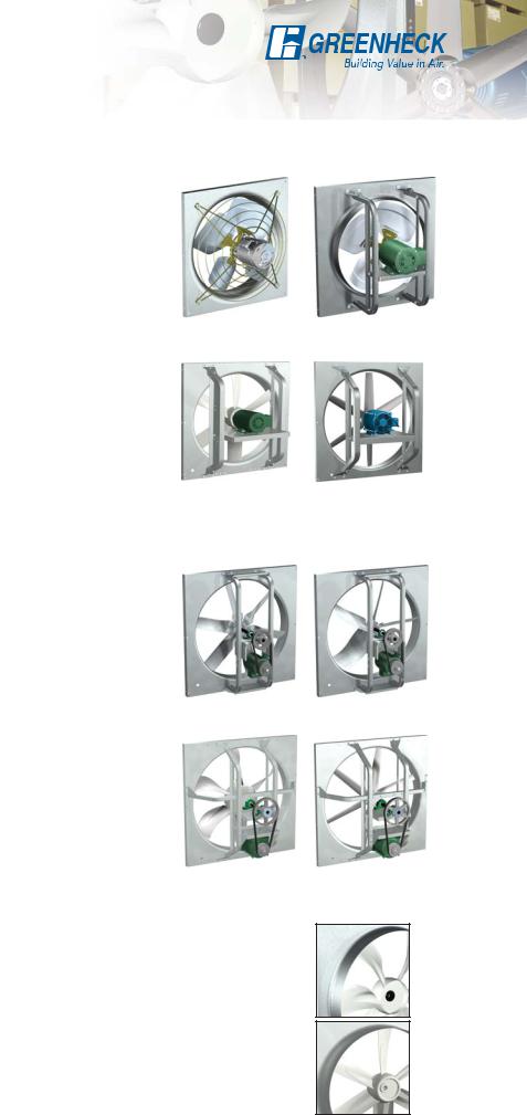
Sidewall Propeller Fans
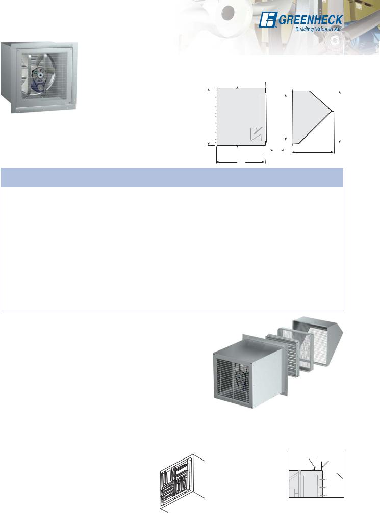
Greenheck’s sidewall propeller fan line is the ideal choice for factory and warehouse applications where high volumes of air and low pressures are required. From general ventilation to industrial duty, the range of construction and performance capabilities offered in this catalog represent the most comprehensive sidewall propeller fan line in the industry.
Performance spans the range between 300 to 87,000 cfm (510 to 147,814 m3/hr) with static pressures to 1.0 in. wg (249 Pa). Fan sizes range from 8 to 54 inches (203 to 1372 mm) for direct drive and 20 to 72 inches (508 to 1829 mm) for belt drive. Regardless of fan size, performance or duty level, all Greenheck sidewall propeller fans are built to perform with the same high standards of reliability and durability.
All models are available in exhaust or supply arrangements. Propellers are available in fabricated steel, fabricated aluminum or cast aluminum. Drive frames and panels are constructed to match the level of duty and the motor size from the smallest low volume model to the largest industrial duty fan.
There is a wide variety of fans to choose from including:
•Three air flow directions; exhaust, supply and reversible
•Both belt drive and direct drive fans
•Three levels of construction from commercial to industrial
•Multiple blade designs for low sound and optimum efficiency
Greenheck Fan Corporation certifies that the SE1, SS1, SE2, SS2, SC3E, SC3S, SBE, SBS, SBCE and SBCS models shown herein are licensed to bear the AMCA Seal. The ratings shown are based on tests and procedures performed in accordance with AMCA Publication 211 and AMCA Publication 311 and comply with the requirements of the AMCA Certified Ratings Program.
Sidewall Direct Drive, Sidewall Belt Drive, Sidewall Belt Driven Cast and Sidewall Cast models are listed for electrical (UL/cUL 705) File no. E40001
*UL is optional and must be specified
Leading Edge Technical Support
When product and IOM (Installation, Operation and Maintenance Manual) information is needed, our products are supported by the industry’s best product literature, electronic media and Computer Aided Product Selection (CAPS) program. You’ll also find this information on our website at
Our national and international representative organization provide personal service and expertise. To locate your nearest Greenheck representative, call 715-359-6171 or visit our website at 
Quick Delivery and Quick Build Programs
There are several Sidewall Propeller Fans available through our Quick Build (QB) and Quick Delivery (QD) programs. The QB program provides custom built to order products shipped three, five, or ten days after ordered. Allowing you the flexibility of knowing that your fan can be made to order and shipped in as little as three days.
Other products are available from our Quick Delivery (QD) program. The QD program provides same day shipments of Greenheck products from our strategically located warehouses throughout the world.
2
Model Comparison
Direct Drive Fan Selection
Three propeller and drive frame combinations are available. Models SE1 and SS1 are designed for smaller size applications where lower volumes and static pressures are found. Models SE2, SS2, SCE3 and SCS3 are designed and constructed for applications with higher volumes and static pressures.
|
Construction |
Models |
Size Range |
Performance |
|
|
|
|
Levels |
diameter |
|
|
|||
|
|
|
|
|
|||
|
|
|
|
|
|
|
|
|
Fabricated |
|
|
Up to 6,700 cfm |
|
|
|
|
aluminum |
SE1 |
8 to 24 in. |
|
|
||
1 |
(11,383) and up to |
|
|
||||
propeller riveted |
SS1 |
(203 to 610) |
|
|
|||
|
to the hub |
|
|
5/8 in. wg (156) |
|
|
|
|
|
|
|
|
|
||
|
Fully welded and |
|
|
Up to 45,000 cfm |
|
|
|
|
gusseted steel |
SE2 |
16 to 54 in. |
|
|
||
2 |
(76,455) and up to |
Sizes 8 to 12 |
Sizes 12 to 24 |
||||
blade and hub |
SS2 |
(406 to 1372) |
|||||
|
|
|
|
|
Level 1 |
Level 1 |
|
|
design |
|
|
1 in. wg (249) |
|
|
|
|
|
|
|
|
|
||
|
Cast aluminum |
SCE3 |
24 to 54 in. |
Up to 45,000 cfm |
|
|
|
3 |
SCS3 |
(76,455) and up to |
|
|
|||
air foil blades |
(610 to 1372) |
|
|
||||
|
|
SCR3 |
|
1 in. wg (249) |
|
|
|
All measurements given in in. (mm), cfm (m3/hr) or in. wg (Pa). |
|
|
|
||||
|
|
|
|
|
|
|
|
Belt Drive Fan Selection Propeller Types
Level 2 |
Level 3 |
Three propeller drive frame construction levels and two blade designs are available. The application requirements for sound and static pressure determine propeller type. Propellers are available in fabricated steel, fabricated aluminum or cast aluminum.
|
Construction |
Models |
Size Range |
Performance |
|
|
|
Levels |
diameter |
|
|||
|
|
|
|
|||
|
|
|
|
|
|
|
|
Galvanized steel |
SBE-1 |
20 to 54 in. |
Up to 30,000 cfm |
|
|
1 |
blades riveted to |
(50,970) and up to |
|
|||
SBS-1 |
(508 to 1372) |
|
||||
|
the hub |
5/8 in. wg (156) |
|
|||
|
|
|
|
|||
|
Dual thickness |
|
|
Up to 53,000 cfm |
|
|
|
galvanized steel |
SBE-2 |
20 to 60 in. |
|
||
2 |
(90,048) and up to |
Level 1 |
||||
blades riveted to |
SBS-2 |
(508 to 1524) |
||||
|
3/4 in. wg (19) |
|||||
|
the hub |
|
|
|
||
|
|
|
|
|
||
|
Fabricated, fully |
|
|
|
|
|
|
welded and |
SBE-3 |
24 to 72 in. |
Up to 87,000 cfm |
|
|
3 |
gusseted steel |
(149,513) and up |
|
|||
SBS-3 |
(610 to 1829) |
|
||||
|
blade and hub |
to 1 in. wg (249) |
|
|||
|
|
|
|
|||
|
design |
|
|
|
|
|
|
Cast aluminum |
SBCE |
24 to 72 in. |
Up to 87,000 cfm |
|
|
3 |
air foil blades |
SBCS |
(149,513) and up |
|
||
(610 to 1829) |
Level 3 |
|||||
|
and hub design |
SBCR |
to 1 in. wg (249) |
|||
|
|
|||||
|
|
|
|
|
Fabricated |
|
All measurements given in in. (mm), cfm (m3/hr) or in. wg (Pa). |
|
|||||
|
|
|||||
|
|
|
|
|
|
|
Blade Designs
L Propeller: Swept, steeply pitched blade design. These propellers typically run at lower RPMs and generate low sound levels making them the best selection for sound critical applications or applications that require the best combination of both air and sound performance. Typically used when the static pressure is 0.5 in. wg (13 mm) or less.
H Propeller: Straight, moderately pitched blade. It is designed for applications where static pressures are above 0.5 in. wg (13 mm). These propellers typically run at higher RPMs and generate slightly higher sound levels than the “L” propellers.
Level 2
Level 3
Cast Aluminum
H Type
L Type
3

Mounting Options Overview
Mounting Option |
Description |
Page |
|
|
wall |
|
|
Standard Wall |
Fan can be mounted |
5 |
|
Mounting |
directly to a wall. |
||
|
|||
|
wall |
|
Standard |
Fan can be horizontally |
|
Horizontal |
mounted to move air up |
6 |
Mounting |
or down. |
|
|
|
|
|
The wall collar is an |
|
|
|
|
|
|
|
|
|
|
|
|
|
|
|
|
|
|
|
Wall Collar |
|
|
easy way to mount the |
7 |
|
|
|
sidewall propeller fan |
|||
|
|
|
|
|
|
|
|
|
|
and its accessories. |
|
|
The wall housing is |
|
Wall Housing |
the easiest and most |
|
flexible way to mount the |
8-9 |
|
|
sidewall propeller fan |
|
|
and all its accessories. |
|
Filtered |
The filtered supply wall |
|
housing is flexible and |
|
|
Supply Wall |
easy way for installations |
10 |
Housing |
where filtering is |
|
|
required. |
|
4
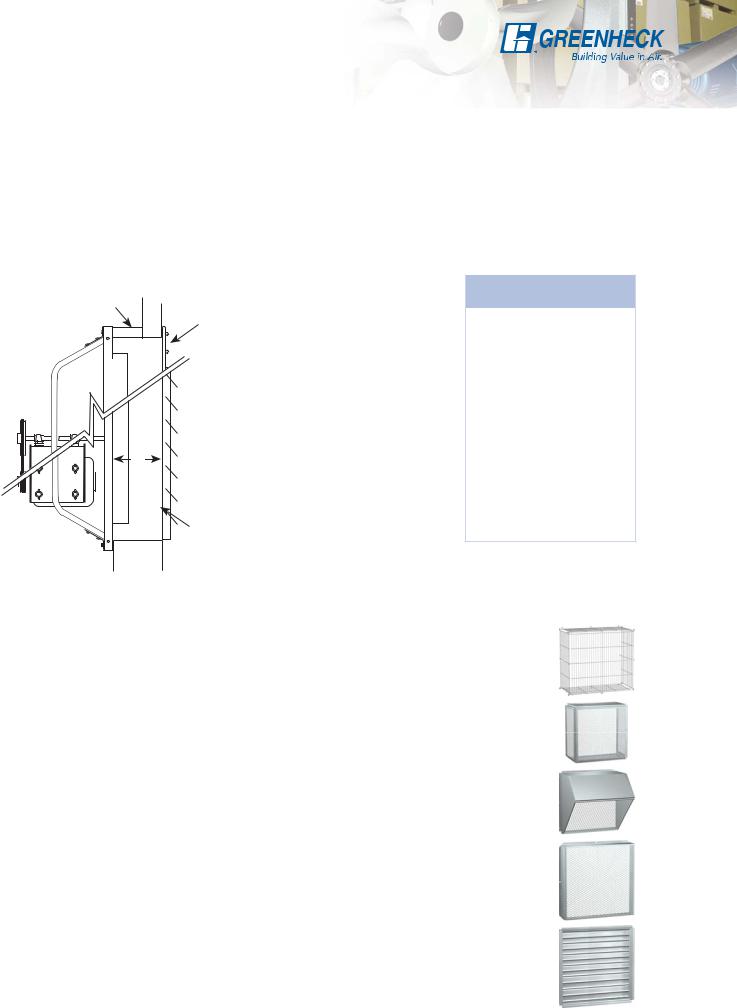
Standard Wall Mounting
Mounting Fan Directly to Wall
The split drawing below illustrates the typical ways of mounting fans directly to the wall when a wall housing or collar is not used.
For exhaust fans, there is a minimum dimension (M) which must be maintained between the propeller and damper or guard to achieve optimum performance (failure to meet this minimum dimension will result in loss of fan performance, increased noise and shortened fan and damper life). There is also a minimum required wall opening dimension (W.O.) to allow the venturi to fit into the wall opening.
See the chart at right for the minimum “M” and wall opening dimensions.
spacer |
|
This installation may |
wall |
guard |
require a spacer (by |
|
||
|
|
others) between the |
|
|
fan and wall to achieve |
|
|
the minimum “M” |
|
|
dimension. |
M |
Fans can be mounted |
directly to a wall |
|
|
only if the wall is of |
|
sufficient thickness to |
damper |
meet the minimum “M” |
dimension as shown |
|
wall |
here. |
|
Fan |
|
M |
Wall |
||
Size |
|
Opening |
|||
|
|
||||
|
|
|
|
||
8 |
6 |
(152) |
101⁄2 (267) |
||
10 |
6 |
(152) |
121⁄2 (318) |
||
12 |
7 |
(178) |
141⁄2 (368) |
||
14 |
8 |
(203) |
161⁄2 (419) |
||
16 |
9 |
(229) |
181⁄2 (470) |
||
18 |
10 |
(254) |
201⁄2 (521) |
||
20 |
12 |
(305) |
221⁄2 |
(572) |
|
24 |
13 |
(330) |
261⁄2 |
(673) |
|
30 |
13 |
(330) |
321⁄2 |
(826) |
|
36 |
14 |
(356) |
381⁄2 |
(978) |
|
42 |
15 |
(381) |
441⁄2 (1130) |
||
48 |
16 |
(406) |
501⁄2 |
(1283) |
|
54 |
17 |
(432) |
561⁄2 |
(1435) |
|
60 |
19 |
(483) |
621⁄2 |
(1588) |
|
72 |
19 |
(483) |
741⁄2 |
(1892) |
|
All dimensions given in inches (mm).
Motor Side Guard
Protective guards of welded steel wire completely enclose the motor and drive side of the fan. Guards are coated with Permatector, a thermal setting polyester urethane. Other paint finishes are also available. Sizes 20 and larger only.
OSHA Motor Side Guard
Protective guards of expanded metal screen in structural steel frames are available to completely enclose the motor and drive side of the fan.
Weatherhood
Weatherhoods shield wall openings and dampers from rain and snow. Weatherhoods are shipped unassembled in kit form for field assembly. Construction is of galvanized steel with wire mesh birdscreen. Mounting flanges have prepunched mounting holes. 45° turn down is for exhaust and 90° turn down is for exhaust and supply. Options include aluminum construction, insect screen and painted finish.
Damper Guard
Damper guards meet the OSHA requirements completely enclose the damper or wall openings on the discharge side of the fan. They are constructed of expanded
galvanized steel screen in galvanized steel frames. Mounting flanges have prepunched mounting holes. Options include aluminum construction and painted finish.
Dampers
Used alone or in conjunction with the wall housing or wall collar, a complete line of dampers is available for exhaust or supply configurations.
5
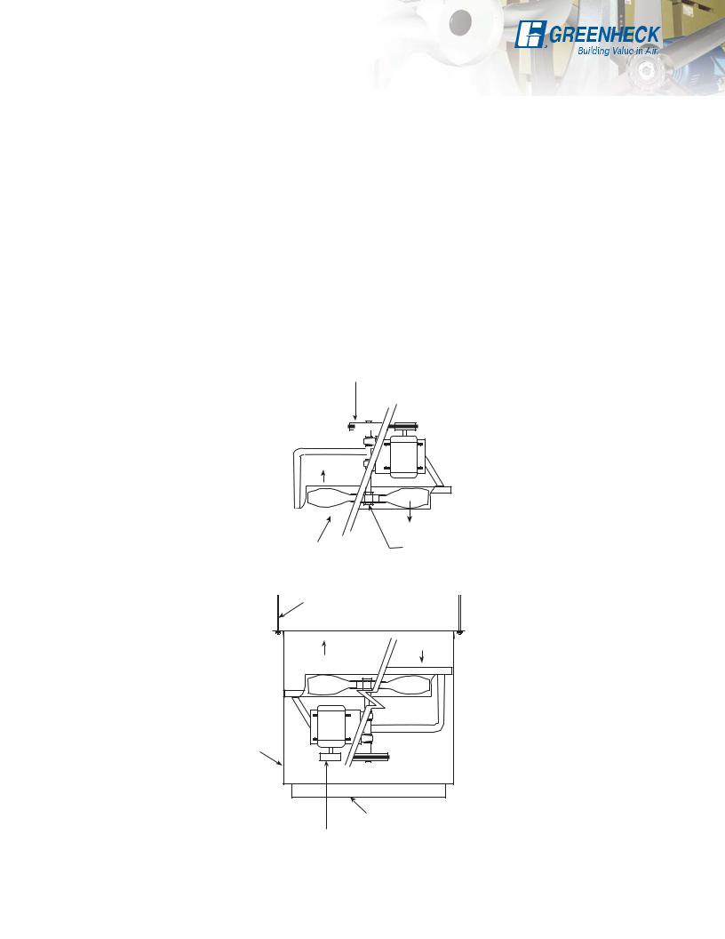
Standard Horizontal Mounting Option
Horizontally mounted fans are available for applications requiring vertical airflow. Typical applications include mounting fans in ductwork or plenums as transfer fans or suspending them from the ceiling in a wall housing for use as recirculation fans. Both belt and direct drive fans can be horizontally mounted. Motors can be mounted on top or on bottom with airflow up or down. Specify configuration best suited for access and service.
Horizontally mounted fans are put under different stresses than fans mounted in a wall. Construction modifications are required depending on motor location (top or bottom) and whether the fan is belt or direct drive.
These modifications may include the following:
A - Grooved shaft with snap rings (belt drive fans)
B - Motor pulley retaining hardware
(belt drive fans with motor on bottom)
C - Reinforcing angles on fan panel - not shown (all fans with motor on bottom)
D - Propeller retaining hardware
(direct drive fans with motor on top)
|
A |
Supply Fan |
Exhaust Fan |
Motor on Top |
Motor on Top |
Air Blowing Upward |
Air Blowing Downward |
|
Airflow |
|
|
|
|
|
|
|
|
|
|
|
|
|
|
|
|
|
|
|
|
|
|
|
|
|
|
|
|
|
|
|
|
|
|
|
|
|
|
|
|
|
|
|
|
|
|
|
|
|
|
Airflow |
|||
Guarding is strongly |
|
|
D - Retaining Hardware |
|||||
recommended |
|
|
|
|
|
|||
|
|
|
|
|
|
|
|
|
|
|
|
|
|
|
|
|
|
|
Hangers by others |
|
|
Motor on Bottom |
Airflow |
Motor on Bottom |
|
Air Blowing Upward |
Air Blowing Downward |
||
Airflow |
|||
(Shown as suspended |
(Shown as suspended |
||
|
|||
installation with fan |
|
installation with fan |
|
mounted in wall housing.) |
|
mounted in wall housing.) |
|
|
Wall |
|
|
|
Housing |
|
|
|
Exhaust Fan |
Supply Fan |
|
|
Guard or Diffuser |
|
|
|
B |
|
NOTE: Protective guarding is also required below the fan for safety. When guarding is not ordered with the fan, it must be supplied by the installer. When specifying a fan for horizontal mounting, the motor location (top or bottom) and airflow (upward or downward) are required information.
6
Wall Collar Mounting Option
Wall collars offer an alternate method for mounting sidewall propeller fans and the optional accessories shown here. Standard construction is of galvanized steel (painted steel is optional) with heavy gauge mounting flanges and pre-punched mounting holes. 

W.O. |
A |
D |
F |
|
|
|
|
|
|
|
|
|
|
|
|
|
|
|
|
|
|
|
|
|
|
|
|
C |
|
|
|
|
|
|
|
|
|
|
|
|
|
|
|
|
|
|
|
|
|
|
|
|
|
|
|
|
|
|
|
|
|
|
|
|
|
|
|
|
|
||
|
|
|
|
|
|
|
|
|
|
|
|
|
|
|
|
|
|
|
|
|
|
|
|
|
|
|
|
|
|
|
||
|
|
|
|
|
|
|
|
|
|
|
|
|
|
|
|
|
|
|
|
|
|
|
|
|
|
|
|
|
|
|
||
|
|
|
|
|
|
|
|
|
|
|
|
|
|
|
|
|
|
|
|
|
|
|
|
|
|
|
|
|
|
|
||
|
|
|
|
|
|
|
|
|
|
|
|
|
|
|
|
|
|
|
|
|
|
|
|
|
|
|
|
|
|
|
||
|
|
|
|
|
|
|
|
|
|
|
|
|
|
|
|
|
|
|
|
|
|
|
|
|
|
|
|
|
|
|
||
|
|
|
|
|
|
|
|
|
|
|
|
|
|
|
|
|
|
|
|
|
|
|
|
|
|
|
|
|
|
|
||
|
|
|
|
|
|
|
|
|
|
|
|
|
|
|
|
|
|
|
|
|
|
|
|
|
|
|
E |
|
|
|
||
|
|
|
|
|
|
|
|
|
|
|
|
|
|
|
|
|
|
|
|
|
|
|
|
|
|
|
|
|
|
|
|
|
|
|
|
|
|
|
|
|
|
|
|
|
|
|
|
|
|
|
|
|
|
|
|
|
|
|
|
|
|
|
|
|
|
|
|
|
|
|
|
|
|
|
G* |
|
|
|
B |
|
|
|
|
|
|
|
|
|
|
|
|
|
|
|
|
|
||
|
|
|
|
|
|
|
|
|
|
|
|
|
|
|
|
|
|
|
|
|
|
|
|
|
|
|
|
|
|
|
|
|
|
|
|
|
|
|
|
|
|
|
|
|
|
|
|
|
|
|
|
|
|
|
|
|
|
|
|
|
|
|
|
|
|
|
|
Wall Collar |
|
Damper Guard |
|
Weatherhood |
|
Motor Side |
|
|
|
|||||||||||||||||||||
Size |
|
|
|
|
|
|
Guard |
Damper |
||||||||||||||||||||||||
|
|
|
|
|
|
|
|
|
|
|
|
|
|
|
|
|
|
|
|
|
|
|
|
|||||||||
|
A |
B** |
W.O. |
C |
D |
E |
|
|
|
F |
|
Width |
|
|
|
|
|
G* |
|
|
|
|||||||||||
8 |
127⁄8 (327) |
161⁄8 (410) |
141⁄4 (362) |
51⁄2 (140) |
101⁄4 (260) |
131⁄4 (337) |
|
111⁄4 (286) |
101⁄2 (267) |
|
85⁄8 (219) |
10 (254) |
||||||||||||||||||||
10 |
147⁄8 (378) |
161⁄8 (410) |
161⁄4 (413) |
61⁄2 (165) |
121⁄4 (311) |
147⁄8 (378) |
|
133⁄8 (340) |
121⁄2 (318) |
|
9 |
(229) |
|
12 (305) |
||||||||||||||||||
12 |
177⁄8 (454) |
161⁄8 (410) |
191⁄4 (489) |
53⁄8 (137) |
141⁄4 (362) |
163⁄8 (416) |
|
155⁄8 (397) |
141⁄2 (368) |
|
11 |
(279) |
|
14 (356) |
||||||||||||||||||
14 |
197⁄8 (505) |
183⁄8 (467) |
211⁄4 (540) |
63⁄8 (162) |
161⁄4 (413) |
171⁄2 (445) |
|
175⁄8 (448) |
161⁄2 (419) |
|
11 |
(279) |
|
16 (406) |
||||||||||||||||||
16 |
217⁄8 (556) |
183⁄8 (467) |
231⁄4 (591) |
63⁄4 (171) |
181⁄4 (464) |
193⁄8 (492) |
|
195⁄8 (498) |
181⁄2 (470) |
|
11 |
(279) |
|
18 (457) |
||||||||||||||||||
18 |
237⁄8 (606) |
183⁄8 (467) |
251⁄4 (641) |
6 (152) |
201⁄4 (514) |
22 (559) |
|
215⁄8 (549) |
201⁄2 (521) |
|
11 (279) |
|
20 (508) |
|||||||||||||||||||
20 |
257⁄8 (657) |
183⁄8 (467) |
271⁄4 (692) |
61⁄2 (165) |
221⁄4 (565) |
243⁄4 (629) |
|
235⁄8 (600) |
221⁄2 (572) |
|
16 |
(406) |
|
22 (559) |
||||||||||||||||||
24 |
317⁄8 (810) |
183⁄8 (467) |
333⁄4 (857) |
63⁄8 (162) |
261⁄4 (667) |
267⁄8 (683) |
|
303⁄8 (772) |
291⁄8 (740) |
|
18 |
(457) |
|
26 (660) |
||||||||||||||||||
30 |
377⁄8 (962) |
183⁄8 (467) |
393⁄4 (1010) |
61⁄2 (165) |
321⁄4 (819) |
291⁄8 (740) |
|
361⁄2 (927) |
351⁄8 (892) |
|
21 |
(533) |
|
32 (813) |
||||||||||||||||||
36 |
437⁄8 (1114) |
183⁄4 (476) |
453⁄4 (1162) |
63⁄4 (171) |
381⁄4 (972) |
33 (838) |
|
421⁄2 (1080) |
411⁄8 (1045) |
|
22 |
(559) |
|
38 (965) |
||||||||||||||||||
42 |
497⁄8 (1127) |
183⁄4 (476) |
513⁄4 (1314) |
10 (254) |
441⁄4 (1124) |
353⁄4 (908) |
|
481⁄2 (1232) |
471⁄8 (1197) |
|
24 |
(610) |
|
44 (1118) |
||||||||||||||||||
48 |
557⁄8 (1419) |
187⁄8 (479) |
573⁄4 (1467) |
9 (229) |
501⁄4 (1276) |
403⁄8 (1026) |
|
545⁄8 (1387) |
531⁄4 (1353) |
|
27 |
(686) |
|
50 (1270) |
||||||||||||||||||
54 |
617⁄8 (1572) |
201⁄8 (512) |
633⁄4 (1619) |
71⁄2 (191) |
561⁄4 (1429) |
443⁄4 (1137) |
|
607⁄8 (1546) |
591⁄2 (1511) |
|
32 |
(813) |
|
56 (1422) |
||||||||||||||||||
60 |
677⁄8 (1724) |
21 (533) |
693⁄4 (1772) |
71⁄4 (184) |
621⁄4 (1581) |
483⁄8 (1229) |
|
67 (1702) |
|
|
655⁄8 (1667) |
|
32 |
(813) |
|
62 (1575) |
||||||||||||||||
72 |
817⁄8 (2080) |
22 (559) |
833⁄4 (2127) |
71⁄2 (191) |
741⁄4 (1886) |
531⁄4 (1353) |
|
791⁄2 (2019) |
781⁄8 (1984) |
|
32 |
(813) |
|
74 (1880) |
||||||||||||||||||
*Dimensions are for exhaust fan guard. See CAPS for supply fan and for optional OSHA motor side guard dimensions. **All sizes except 20 and 72 are 2 in (51 mm) larger if a VCD damper is used. For complete dimensional information refer to submittal. All dimensions given in inches (mm).
Motor Side Guard — Protective guards of welded steel wire completely enclose the motor and drive side of the fan. Guards are coated with Permatector, a thermal setting polyester urethane. Other paint finishes are also available. Sizes 20 and larger only.
OSHA Motor Side Guard — Protective guards of expanded metal screen in structural steel frames are available to completely enclose the motor and drive side of the fan.
Dampers — Used alone or in conjunction with the wall housing or wall collar, a complete line of dampers is available for exhaust or supply configurations.
Note: Wall collar, fan, damper and guards ship completely factory assembled except when ordered as a kit.. Weatherhood ships loose.
Damper Guard — Damper guards meet the OSHA requirements completely enclose the damper or wall openings on the discharge side of the fan. They are constructed of expanded galvanized steel screen in galvanized steel frames.
Mounting flanges have prepunched mounting holes. Options include aluminum construction and painted finish.
Weatherhood — Weatherhoods shield wall openings and dampers from rain and snow. Weatherhoods are shipped unassembled in kit form for field assembly. Construction is of galvanized steel with wire mesh birdscreen. Mounting flanges have prepunched mounting holes. 45° turn down is for exhaust and 90° turn down is for exhaust and supply. Options include aluminum construction, insect screen and painted finish.
7
Wall Housing Mounting Option
|
|
|
|
|
|
Wall housings are the safest, most efficient and sturdy platform for mounting |
|
|||||||||||||||||||||||||||||
|
|
|
|
|
|
sidewall propeller fans and their optional accessories. Wall housings allow |
|
|||||||||||||||||||||||||||||
|
|
|
|
|
|
for a wide range of mounting arrangements to meet specific applications. It |
|
|||||||||||||||||||||||||||||
|
|
|
|
|
|
|
||||||||||||||||||||||||||||||
|
|
|
|
|
|
is constructed of galvanized steel (painted steel optional) with heavy gauge |
|
|||||||||||||||||||||||||||||
|
|
|
|
|
|
mounting flanges and prepunched |
|
|
|
|
|
|
|
|
|
|
|
|
|
|
|
|
|
|
|
|
|
|
|
|
|
|
||||
|
|
|
|
|
|
|
|
|
|
|
|
|
|
|
|
|
|
|
|
|
|
|
|
|
|
|
|
|
|
|
|
|||||
|
|
|
|
|
|
mounting holes. Protective guards |
|
|
|
|
|
|
|
|
|
|
|
|
|
|
|
|
|
|
|
|
|
|
|
|
|
|
||||
|
|
|
|
|
|
|
|
|
|
|
|
|
|
|
|
|
|
|
|
|
|
|
|
|
|
|
|
|
|
|
|
|||||
|
|
|
|
|
|
of welded steel wire completely |
|
|
|
|
|
|
|
|
|
|
|
|
|
|
|
|
|
|
|
|
|
|
|
|
|
|
||||
|
|
|
|
|
|
protect the drive side of the wall |
|
|
|
|
|
|
|
|
|
|
|
|
|
|
|
|
|
|
|
|
|
|
|
|
|
|
||||
|
|
|
|
|
|
housing. Guards are coated with |
|
|
|
|
|
|
|
|
|
|
|
|
|
|
|
|
|
|
|
|
|
|
|
|
|
|
||||
|
|
|
|
|
|
Permatector, a thermal setting |
|
A |
|
|
W.O. |
|
|
|
|
|
|
|
|
|
D |
|
|
|
|
F |
|
|
||||||||
|
|
|
|
|
|
polyester urethane. Other paint |
|
|
|
|
|
|
|
|
|
|
|
|
|
|
|
|
|
|
|
|
|
|
|
|
|
|
||||
|
|
|
|
|
|
|
|
|
|
|
|
|
|
|
|
|
|
|
|
|
|
|
|
|
|
|
|
|
|
|
|
|||||
|
|
|
|
|
|
finishes are also available. |
|
|
|
|
|
|
|
|
|
|
|
|
|
|
|
|
|
|
|
|
|
|
|
|
|
|
|
|||
|
|
|
|
|
|
Wall housing guards that meet |
|
|
|
|
|
|
|
|
|
|
|
|
|
|
|
|
|
|
|
|
|
|
|
|
|
|
|
|||
|
|
|
|
|
|
|
|
|
|
|
|
|
|
|
|
|
|
|
|
|
|
|
|
|
|
|
|
|
|
|
|
|
||||
|
|
|
|
|
|
the OSHA requirements are also |
|
|
|
|
|
|
|
|
|
|
|
|
|
C |
|
|
|
|
E |
|
|
|
|
|
|
|||||
|
|
|
|
|
|
available. |
|
|
|
|
|
|
|
|
B* |
|
|
|
|
|
|
|
|
|
|
|
|
|
|
|
|
|
|
|
|
|
|
|
|
|
|
|
|
|
|
|
|
|
|
|
|
|
|
|
|
|
|
|
|
|
|
|
|
|
|
|
|
|
|
|
|
||
|
|
|
|
|
|
|
|
|
|
|
|
|
|
|
|
|
|
|
|
|
|
|
|
|
|
|
|
|
|
|
|
|
|
|
|
|
|
|
|
|
|
|
|
|
|
|
|
|
|
|
|
|
|
|
|
|
|
|
|
|
|
|
|
|
|
|
|
|
|
|
|
|
|
|
|
Wall Housing |
|
|
Damper Guard |
|
|
Weatherhood |
|
|
|
|
|
|
|
|
|
|
|
|
|
Material |
|
|||||||||||||
Size |
A |
|
B* |
|
|
W.O. |
C |
D |
|
E |
|
|
F |
|
Width |
Damper |
|
Gauge (ga) |
|
|||||||||||||||||
|
|
|
|
|
|
|
|
|
|
|
|
|
Thickness |
|
||||||||||||||||||||||
|
|
|
|
|
|
|
|
|
|
|
|
|
|
|
|
|
|
|
|
|
|
|
|
|
|
|
|
|
|
|||||||
8 |
131⁄4 (337) |
|
19 (483) |
|
|
141⁄4 (362) |
51⁄2 (140) |
101⁄4 (260) |
|
131⁄4 (337) |
|
111⁄4 (286) |
|
101⁄2 (267) |
10 (254) |
20 |
|
|
|
|
|
|||||||||||||||
10 |
151⁄4 (387) |
|
19 (483) |
|
|
161⁄4 (413) |
61⁄2 (165) |
121⁄4 (311) |
|
147⁄8 (378) |
|
133⁄8 (340) |
|
121⁄2 (318) |
12 (305) |
20 |
|
|
|
|
|
|||||||||||||||
12 |
181⁄4 (464) |
|
23 (584) |
|
|
191⁄4 (489) |
53⁄8 (137) |
141⁄4 (362) |
|
163⁄8 (416) |
|
155⁄8 (397) |
|
141⁄2 (368) |
14 (356) |
20 |
|
|
|
|
|
|||||||||||||||
14 |
201⁄4 (514) |
|
26 (660) |
|
|
211⁄4 (540) |
63⁄8 (162) |
161⁄4 (413) |
|
171⁄2 (445) |
|
175⁄8 (448) |
|
161⁄2 (419) |
16 (406) |
20 |
|
|
|
|
|
|||||||||||||||
16 |
221⁄4 (565) |
|
27 (686) |
|
|
231⁄4 (591) |
63⁄4 (171) |
181⁄4 (464) |
|
193⁄8 (492) |
|
195⁄8 (498) |
|
181⁄2 (470) |
18 (457) |
20 |
|
|
|
|
|
|||||||||||||||
18 |
241⁄4 (616) |
|
28 (711) |
|
|
251⁄4 (641) |
6 (152) |
201⁄4 (514) |
|
22 (559) |
|
215⁄8 (549) |
|
201⁄2 (521) |
20 (508) |
20 |
|
|
|
|
|
|||||||||||||||
20 |
261⁄4 (667) |
|
32 (813) |
|
|
271⁄4 (692) |
61⁄2 (165) |
221⁄4 (565) |
|
243⁄4 (629) |
|
235⁄8 (600) |
|
221⁄2 (572) |
22 (559) |
18 |
|
|
|
|
|
|||||||||||||||
24 |
321⁄4 (819) |
|
37 (940) |
|
|
333⁄4 (857) |
63⁄8 (162) |
261⁄4 (667) |
|
267⁄8 (683) |
|
303⁄8 (772) |
|
291⁄8 (740) |
26 (660) |
18 |
|
|
|
|
|
|||||||||||||||
30 |
381⁄4 (972) |
|
38 (965) |
|
393⁄4 (1010) |
61⁄2 (165) |
321⁄4 (819) |
|
291⁄8 (740) |
|
361⁄2 (927) |
|
351⁄8 (892) |
32 (813) |
18 |
|
|
|
|
|
||||||||||||||||
36 |
441⁄4 (1124) |
|
39 (991) |
|
453⁄4 (1162) |
63⁄4 (171) |
381⁄4 (972) |
|
33 (838) |
|
421⁄2 (1080) |
|
411⁄8 (1045) |
38 (965) |
18 |
|
|
|
|
|
||||||||||||||||
42 |
503⁄8 (1280) |
|
44 (1118) |
|
513⁄4 (1314) |
10 (254) |
441⁄4 (1124) |
|
353⁄4 (908) |
|
481⁄2 (1232) |
|
471⁄8 (1197) |
44 (1118) |
18 |
|
|
|
|
|
||||||||||||||||
48 |
563⁄8 (1432) |
|
44 (1118) |
|
573⁄4 (1467) |
9 (229) |
501⁄4 (1276) |
|
403⁄8 (1026) |
|
545⁄8 (1387) |
|
531⁄4 (1353) |
50 (1270) |
18 |
|
|
|
|
|
||||||||||||||||
54 |
623⁄8 (1584) |
|
52 (1321) |
|
633⁄4 (1619) |
71⁄2 (191) |
561⁄4 (1429) |
|
443⁄4 (1137) |
|
607⁄8 (1546) |
|
591⁄2 (1511) |
56 (1422) |
16 |
|
|
|
|
|
||||||||||||||||
60 |
683⁄8 (1737) |
|
54 (1372) |
|
69 3⁄4 (1172) |
71⁄4 (184) |
621⁄4 (1581) |
|
483⁄8 (1229) |
|
67 (1702) |
|
655⁄8 (1667) |
62 (1575) |
16 |
|
|
|
|
|
||||||||||||||||
72 |
831⁄8 (2111) |
|
60 (1524) |
|
843⁄4 (2153) |
71⁄2 (191) |
741⁄4 (1886) |
|
531⁄4 (1353) |
|
791⁄2 (2019) |
|
781⁄8 (1984) |
74 (1880) |
12 |
|
|
|
|
|
||||||||||||||||
* B dimension will increase by 6 in (152 mm) when a heavy duty motorized backdraft damper is specified. For complete dimensional information refer to submittal. All dimensions given in inches (mm).
Dampers — Used alone or in conjunction with the wall housing or wall collar, a complete line of dampers is available for exhaust or supply configurations.
Damper Guard — Damper guards meet the OSHA requirements completely enclose the damper or wall openings on the discharge side of the fan. They are constructed of expanded galvanized steel screen in galvanized steel frames. Mounting flanges
have prepunched mounting holes. Options include aluminum construction and painted finish.
Weatherhood — Weatherhoods shield wall openings and dampers from rain and snow. Weatherhoods are shipped unassembled in kit form for field assembly. Construction is
of galvanized steel with wire mesh birdscreen. Mounting flanges have prepunched mounting holes. 45° turn down is for exhaust and 90° turn down
is for exhaust and supply. Options include aluminum construction, insect screen and painted finish.
Diffusers - Wall Housing Mounted - Manual Operator
Diffusers are constructed with heavy
gauge galvanized steel frames, blades and prepunched mounting flanges. They are designed to mount to the interior end of the wall
housing when used in the supply configuration. Manual quadrants set the angle of the blades to deflect air in 1, 2 or 4 directions.
8
Closure Angles
An extra set of mounting flanges is available for field installation to
close off the interior wall opening for a finished appearance.
Closure Angles |
|
Mounting |
|
|
Angles |
||
|
Wall |
||
INTERIOR |
EXTERIOR |
||
|
Wall Housing Mounting Arrangements
The wall housing is designed to reduce installation time and provide maximum installation flexibility. Attached accessories such as backdraft dampers, guards and weatherhoods may mount to either end. As a result a wide variety of configurations are available to accommodate the needs of the system designer.
The following information will help determine the correct arrangement required. When ordering specify arrangement by the drawing number 1A, 2A, 1B or 2B as shown in the diagrams below.
NOTE: Weatherhoods are strongly recommended for all configurations to help prevent moisture infiltration. Mounting flange, damper and guard ship factory mounted on all arrangements as shown except when ordered as a kit.
Mounting Arrangements for Interior Service Applications
The arrangements shown below are the most commonly used and should be considered first for most applications. The choice of flush interior or exterior mounting are based on appearance or space considerations.
Belts, pulleys and motors are serviced from inside the building with these arrangements. For applications requiring service from outside the
building, see reverse mounting arrangements below.
Flush exterior |
|
Exterior |
Interior |
|
|
||||
1A Exhaust |
Interior |
Wall |
||
|
|
|
|
|
|
|
|
|
|
Exhaust
Supply
|
Flush interior |
|
Wall |
Exterior |
2A Exhaust |
|
|
|
|
|
Exhaust |
|
|
Supply |
1B Supply |
Wall |
Wall |
2B Supply |
|
|
Mounting Arrangements for Exterior Service Applications (Optional)
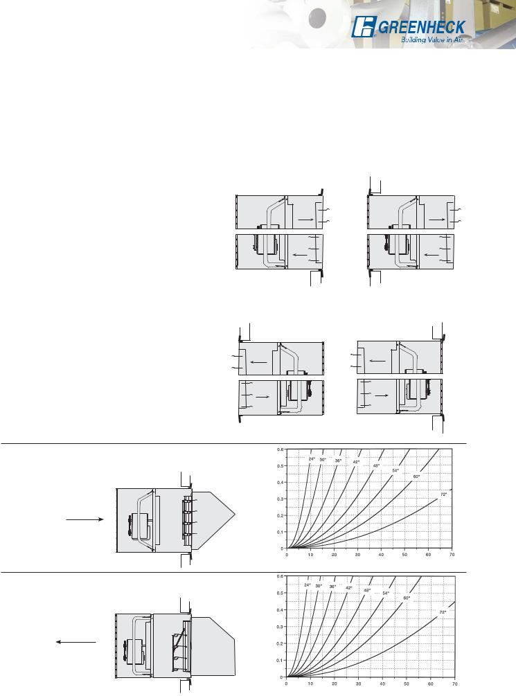
Reverse mounting a wall housing simply involves installing the wall housing through the wall opening in the opposite direction of the above configurations. This results in an opposite effect on fan function. An exhaust fan in a wall housing will function as a supply fan when the housing is reverse mounted.
Example: When the exhaust arrangement shown as 1A is reversed (shown as 1A-R) the same unit now becomes a supply arrangement. The construction, fan position and mounting angle location in both configurations remain identical.
Interior
|
Flush interior |
|
Wall |
Exterior |
1A-R Supply |
|
|
|
|
Supply |
|
Exhaust
Wall |
1B-R Exhaust |
|
|
|
|
Flush exterior |
|
Exterior |
|
2A-R Supply |
Interior |
Wall |
|
|
|
|
|
Supply |
|
|
|
Exhaust |
|
|
|
2B-R Exhaust |
|
Wall |
|
|
|
|
|
EXHAUST FAN in Wall Housing with Gravity Damper and Weatherhood
Airflow
Static Pressure
Pressure Loss
CFM x 1000
SUPPLY FAN in Wall Housing with Gravity Damper and Weatherhood
Airflow
Static Pressure
Pressure Loss
CFM x 1000
9
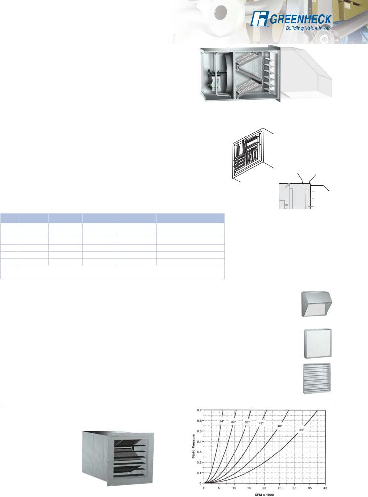
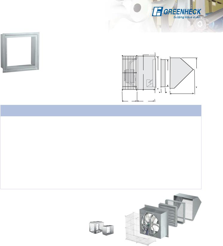
Filtered Supply Wall Housing
Mounting Options
Filtered supply wall housings are available in seven sizes for fans ranging from size 24 to 54 inches (610 to 1372 mm).
They are designed with the draw-thru concept to achieve the highest filter and fan efficiencies.
Standard construction is galvanized steel (painted steel optional). Mounting flanges are factory installed for either flush exterior or flush interior. Permanent 2 inch (51 mm) washable filters are accessed through a bolted panel and can be easily removed for cleaning.
All accessory items available with the standard wall housing can be used with the filtered supply wall housing.
Diffusers - Wall Housing Mounted - Manual Operator |
|
|
|
|||||||
Diffusers are constructed with heavy gauge galvanized steel frames, |
|
|
|
|||||||
blades and prepunched mounting flanges. They are designed to mount to |
|
|
|
|||||||
the interior end of the wall housing when used in the supply configuration. |
|
|
||||||||
Manual quadrants set the angle of the blades to deflect air in 1, 2 or 4 |
|
|
|
|||||||
directions. |
|
|
|
|
|
|
|
Angles |
||
|
|
|
|
|
|
|
Closure Angles |
|
Mounting |
|
|
|
|
|
|
|
|
|
|
||
Closure Angles |
|
|
|
|
INTERIOR |
Wall |
EXTERIOR |
|||
|
|
|
|
|
||||||
|
|
|
|
|
|
|
||||
An extra set of mounting flanges is available for field installation to close |
|
|
|
|||||||
off the interior wall opening for a finished appearance. |
|
|
|
|
||||||
Size |
A |
B |
C |
Wall Opening |
Filter Size & Quantity |
Notes: |
|
|
||
1. Additional bracing (by others) above or below the |
||||||||||
24 |
321⁄4 (819) |
63 (1600) |
24 (610) |
333⁄4 (857) |
(4) |
231⁄4 (591) x 161⁄4 (413) |
||||
housing is required for support of the filtered supply |
||||||||||
30 |
381⁄4 (972) |
65 (1651) |
26 (660) |
393⁄4 (1010) |
(4) |
245⁄8 (625) x 191⁄4 (489) |
wall housing. |
|
|
|
36 |
441⁄4 (1124) |
671⁄4 (1708) |
281⁄4 (718) |
453⁄4 (1162) |
(6) |
231⁄4 (591) x 221⁄8 (562) |
Attach at least two supports (either vertical or angled) |
|||
42 |
501⁄8 (1273) |
727⁄8 (1851) |
34 (864) |
513⁄4 (1314) |
(6) |
241⁄8 (613) x 251⁄8 (638) |
to the end of housing. |
|
|
|
Vertical supports must carry 500# minimum per |
||||||||||
48 |
561⁄8 (1426) |
727⁄8 (1851) |
34 (864) |
573⁄4 (1467) |
(12) |
231⁄4 (591) x 183⁄4 (476) |
||||
support, and angled (45°) supports a minimum of 750# |
||||||||||
54 |
623⁄8 (1584) |
7911⁄16 (2024) |
4011⁄16 (1033) |
633⁄4 (1619) |
(12) |
231⁄4 (591) x 203⁄4 (527) |
per support. |
|
|
|
2. Filtered supply wall housing, fan damper and guards |
||||||||||
Filters are 2 in (51 mm) nominal thickness. Above filter sizes are actual dimensions. All dimensions given in |
||||||||||
ship completely factory assembled. Weatherhood |
||||||||||
inches (mm). |
|
|
|
|
|
ships loose. |
|
|
||
Weatherhood
Weatherhoods shield wall openings and dampers from rain and snow. Weatherhoods are shipped unassembled in kit form for field assembly. Construction is of galvanized steel with wire mesh birdscreen. Mounting flanges have prepunched mounting holes. 45° turn down is for exhaust and 90° turn down is for exhaust and supply. Options include aluminum construction, insect screen and painted finish.
Damper Guard
Damper guards meet the OSHA requirements completely enclose the damper or wall openings on the discharge side of the fan. They are constructed of expanded galvanized steel screen in galvanized steel frames. Mounting flanges have prepunched mounting holes. Options include aluminum construction and painted finish.
Dampers
Used alone or in conjunction with the wall housing or wall collar, a complete line of dampers is available for exhaust or supply configurations
FILTERED SUPPLY FAN in Wall Housing with Filter
Bank, Gravity Damper and Weatherhood
Note: This chart is for manual calculations only. CAPS has filter losses built into the selection tool when the filtered housing option is selected.
10
Backdraft Dampers
Used alone or in conjunction with the wall housing or wall collar, backdraft dampers are available for exhaust or supply configurations. Backdraft dampers are constructed with galvanized frames, aluminum blades and vinyl blade seals. Actuators are available in 24, 120, 208, 230 or 460 volts. Actuators for 50 cycle voltages are also available. Actuators for 50 cycle voltages are also available.
Damper Type |
|
Description |
Flush Exterior |
Flush Interior |
Exhaust - Gravity or Motorized¹ |
WD-320 and WD-300 |
Exhaust backdraft dampers |
For applications where the |
|
|
|
exhaust dampers are |
are Model WD-320, which |
mounting flange is required |
|
|
available as either gravity |
has the prepunched |
on the inlet end of the |
|
|
operated or motorized |
mounting flange located |
damper (so that the damper |
|
|
|
on the outlet end of the |
projects to the exterior), the |
|
|
|
damper for a flush exterior |
Model WD-300 is available. |
Airflow |
Airflow |
|
appearance. |
|
Wall Housing Installation |
|
Wall Installation |
Model WD-320 shown |
|
|
|
|
Supply – Gravity² |
|
|
• WD-430 and WD-420 |
• Model WD-430 has a |
• Model WD-420 is for |
||
|
|
|
|
intake dampers are |
|
prepunched mounting |
applications where a |
|
|
|
|
only available as gravity |
|
flange located on the inlet |
prepunched mounting |
|
|
|
|
operated |
|
end of the damper for a |
flange is required on the |
|
|
|
• |
Galvanized steel frame |
|
flush exterior appearance |
outlet end of damper (so |
|
|
|
|
|
the damper projects to |
||
|
Airflow |
Airflow |
|
and aluminum blades |
• |
Flange on intake |
|
|
|
|
|
the exterior) |
|||
|
|
|
|
|
|
|
|
|
|
|
|
|
|
|
• Flange on discharge |
Wall Housing Installation |
Wall Installation |
Model WD-430 shown |
|
|
|
||
Supply - Motorized³ |
|
• WD-220 and WD-210 |
• Model WD-220 has a |
• Model WD-210 is for |
|||
|
|
|
|
intake dampers are only |
|
prepunched mounting |
applications where |
|
|
|
|
available as motorized |
|
flange located on the inlet |
a mounting flange is |
|
|
|
• |
Galvanized steel frame |
|
end of the damper for a |
required on the outlet end |
|
|
|
|
flush exterior appearance |
of the damper (so that |
||
|
|
|
|
and aluminum blades |
|
||
|
Airflow |
|
|
|
|
the damper projects to |
|
|
Airflow |
|
|
|
|
||
|
|
|
|
|
• |
Flange located opposite |
the exterior) |
|
|
|
|
|
|
of motor side of the |
• Flange located on motor |
|
|
|
|
|
|
damper |
side of the damper |
Wall Housing Installation |
Wall Installation |
Model WD-220 shown |
|
|
|
||
Volume Control/Heavy Duty Dampers
Volume control dampers are available for exhaust or supply configurations and may be used alone or in conjunction with the wall housing or wall collar. Constructed with heavy galvanized steel frames and blades, model VCD dampers are designed to handle higher air volumes than the standard backdraft damper. Dampers are available in standard leakage (VCD-20), low leakage (VCD-23) and insulated low leakage (VCD-34) configurations. Actuators are available in 24, 120, 208, 230 or 460 volts. Actuators for 50 cycle voltages are also available.
Damper Type |
Description |
Flush Exterior |
Flush Interior |
Exhaust or Supply - Motorized |
Model VCD-20 - Standard leakage |
The VCD damper has the |
N/A |
|
Model VCD-23 - Low leakage |
parallel blade set-up and |
|
|
a prepunched mounting |
|
|
|
– This damper has blade and jamb |
|
|
|
flange that provides a flush |
|
|
|
seals for minimal leakage when |
|
|
|
exterior appearance. |
|
|
|
closed. |
|
|
|
|
|
|
Airflow |
Model VCD-34 - Insulated low |
|
|
|
|
|
|
|
leakage – This damper has blade |
|
|
|
and jamb seals for minimal |
|
|
Airflow |
leakage when closed. Blades are |
|
|
|
constructed with 1⁄2 in. (13 mm) |
|
|
|
polystyrene insulation between two |
|
|
Wall Housing Installation Wall Installation |
galvanized steel skins. |
|
|
¹ Model WD-320 and WD-300 are used with fans where the motor is 5 hp or less. For fans with motors larger than 5 hp, the Model GM-31 medium duty gravity backdraft damper or the Model VCD heavy duty motorized backdraft dampers are required.
²Model WD-430 and WD-420 are used with fans where the motor is 5 hp or less. For fans with motors larger than 5 hp, the Model VCD heavy duty motorized backdraft dampers are required.
³Model WD-220 and WD-210 are used with fans where the motor is 3 hp or less. For fans with motors larger than 3 hp, the Model VCD heavy duty motorized backdraft damper is required.
Note: Wall housing length increases by 6 inches (152 mm) when a heavy duty backdraft damper is specified. |
11 |
Other Options and Accessories
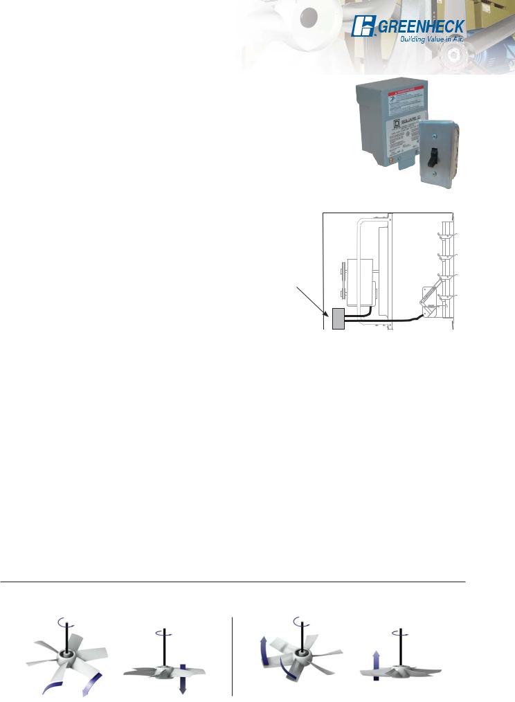
Electrical
Disconnect Switches
Toggle type and heavy duty disconnect switches are available for positive electrical shut-off and safety in servicing fans. The following switches are available to meet individual electrical requirements and can be factory mounted or shipped loose for field mounting. Wiring from the motor to the disconnect box is provided with factory mounted disconnect switches.
•NEMA-1 - General purpose
•NEMA-3R - Rainproof
•NEMA 4 - Watertight
•NEMA-3R & NEMA 4 - Heavy Duty
•NEMA-7 & 9 - for Class 1 and Class 2 hazardous locations.
1-Point Wiring
Available when the following items are selected: common voltages on the motor and the actuator, disconnect mounted and wired and a wall housing. The wires are pulled from the motor and the actuator on the damper to the disconnect box. (Hard wiring of the components to the disconnect switch is by others.)
Exception: When a specific voltage is not available on the actuator, Greenheck will provide a hard wired transformer to the actuator. Greenheck will then pull the wires from the transformer to the disconnect box.
UL/cUL 705
1-Point wiring
Junction Box or Disconnect
NEMA-3R
and NEMA-1
All belt and selected direct drive fans with TE standard efficiency, single speed motors are available with the UL705 listing for electrical.
Extended Wiring Pigtail
Available only in conjunction with factory mounted disconnect switches, liquid tight wiring pigtails allow direct hook-up to the power supply which eliminates field wiring at the fan. Internal or external power supply can be specified.
End Switches
Factory mounted end switches allow the damper to open completely before the fan is energized. This will reduce the back pressure and brake horsepower load on the fan motor at startup. (Field supplied motor starter with a relay is required to complete the wiring on a system using an end switch.)
Options
Coatings
A variety of special coatings ranging from enamels to phenolics are available for decorative or protective purposes. When a special coating is selected for the fan, all accompanying accessory items are also coated unless so specified. Consult your local representative for more details.
Welded and Painted Fan Construction
For applications where extra heavy construction is required, welded steel construction is available. With this option, all stationary connections which are normally bolted are welded and coated with an industrial grade paint. This option applies to belt drive level 3 fans and direct drive level 2 and 3 fans only.
Propeller Fan Rotation Guide
Propeller blade should cup and throw the air when rotating in the correct rotation as shown below.
12
 Loading...