


Franke Consumer Products FPL 607 I XS 645H, FPL 907 I XS 645H, FPL 457 I XS 645H, FPL 607 I, FPL 907 I User Manual
GB
IT
FR
DE
TR
HR
PL
Instructions f
Cooker Hood
Istruzioni per
Cappa
Mode d’empl
Hotte de Cuisine
Bedienungsanleit
Dunstabzugshaube
Ku ım ve mon
Davlumbaz
Upute za kor
Napa
Instrukcja
Okap kuchenny
FPL 607 I
FPL 907 I
FPL 457 I XS 645H
FPL 607 I XS 645H
FPL 907 I XS 645H

Instructions Manual
INDEX
RECOMMENDATIONS AND SUGGESTIONS..........................
CHARACTERISTICS................................
INSTALLATION...................................
USE.............................................
MAINTENANCE....................................
EN |
|
2 |
|
2 |

Libretto di Istruzioni
INDICE
CONSIGLI E SUGGERIMENTI.........................
CARATTERISTICHE............................................
INSTALLAZIONE...................................
USO............................................
MANUTENZIONE...............................................
IT |
|
3 |
|
3 |

Manuel d’Instructions SOMMAIRE
CONSEILS ET SUGGESTIONS..............................
CARACTERISTIQUES................................
INSTALLATION....................................
UTILISATION.....................................
ENTRETIEN.......................................
FR |
|
4 |
|
4 |

Bedienungsanleitung |
|
INHALTSVERZEICHNIS |
|
EMPFEHLUNGEN UND HINWEISE............................ |
42 |
CHARAKTERISTIKEN............................... |
|
MONTAGE........................................ |
|
BEDIENUNG..................................... |
. |
WARTUNG........................................ |
|
DE |
|
5 |
|
5 |

Kullanim Kilavuku
IÇERIKLER
TAVSIYELER VE ÖNERILER..............................
ÖZELLIKLER.............................................
MONTAJ......................................................
KULLANIM........................................
BAKIM...........................................
TR |
|
6 |
|
6 |

Uputstva za Korištenje
KAZALO
SAVJETI I PREPORUKE................................
SVOJSTVA PROIZVODA..................................................
INSTALIRANJE..........................................................
KORIŠTENJE................................................
ODRŽAVANJE...........................................................
HR |
|
7 |
|
7 |

Instrukcja Obslugi
SPIS! CITRE
UWAGI I |
SUGESTIE............................................ |
|
WŁA! CIWO! |
TECHNICZNE............................ |
76 |
INSTALACJA................................................. |
|
|
U" YTKOWANIE................................................. |
|
|
KONSERWACJA................................................ |
|
|
PL |
|
8 |
|
8 |
RECOMMENDATIONS AND SUGG
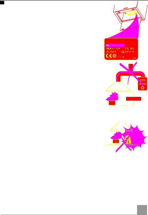
 The Instructions for ofUsethiapplsapplianceyto severa.Accordinglylversions, you may find descripationdos nooft individuaapplytol youfeaturrspescifithc appliance.


INSTALLATION |
|||
• |
The manufacturer wildamagelnostresultibehe |
||
|
improper |
installation. |
|
• |
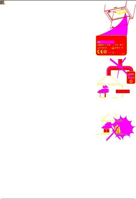
The minimum safety pdistancand theebetwxt |
||
|
mm. |
|
|
• |
Check that the mainindicatesvoltagdeoncot |
||
|
to the inside of the hood. |
||
• |
For Class I |
appliancesower,supplchecyk gut |
|
|
earthing. |
|
|
|
Connect |
the |
extractoarpiptoe thofe minex |
|
mm. The route of thebleflu.e must b |
||
• |
Do not |
connect the sextractocarryinrg hc |
|
|
(boilers, |
fireplaces, etc.). |
|
• |
If the extractor electricaisused linappliaconjuncetiosn( |
||
|
ing appliances), a sufficienstbe guarantetdegrede io |
||
|
order to |
prevent the itchebackflonmuswotf havexhae |
|
|
communicating |
directloyguarantewith thee thopeenen |
|
rrrecanyt o eirs to650 atthaetfix stiuatce p
rroug120h s possi
usmets duct
.thganons-bu onm muin nThge k eaern tai
USE |
|
|
|
|
|
|
|
|
|
|
|
|
|
|
|
|
|
|
|
|
|
|
|
||
• |
The extractor |
hood fohars |
domestibeendesignecuse d |
|
|
|
|
ateley |
||||
|
kitchen |
smells. |
|
|
|
|
|
|
|
|
|
|
• |
Never |
use the |
hoodicfohritpurposehas besn |
othedesignedrtha.n |
|
|
wh |
|||||
• |
Never |
leave |
high nakeitd |
iflamesins operaunde |
onth.e |
|
|
|
|
|
||
|
|
hood |
when |
|||||||||
• |
Adjust |
the |
flamebottoinensitmofy thtoe dp |
lyit, |
|
|
ontmakinogthesur |
|||||
|
||||||||||||
|
that it |
does |
not engulf |
the sides |
650 mm min. |
|
||||||
•Deep fat fryers musrintgbeusecontinuousl:overheateydmonoiltorecadn dburs into flames. 
•Do not flambè under the range hood; risk of fire
•This appliance is no(includintintendegdchildrenfor use) bwityhpersonseduce physical, sensory orf mexperiencntalcapabilitieseand knowledge,or lac,k o unless they have beeionngiveconcerninsupervisiogusenoforthinstructeappliance by a person responsible for their
•Children should be dsuperviseonot pladytowitensuh ncehey.
MAINTENANCE |
|
|
|||
• |
Switch |
off |
or |
unplugsupplthey appliancbefore |
aianys |
|
maintenance |
work. |
|
||
• |
Clean |
and/or replaciede timthe Filterperiods. af |
cif |
||
• |
Clean |
the |
hood |
usinquigda detergentampclo .h a |
al l |
The symboonl the product or thionsitproducspa kagintmayg noindicatetbe treatesthadt as household waste. Insteathde iapplicabltshall bee collectihandedovenrpointot for the of electrical and electronithis produccequipmenttis dispos.lpBy ednsuringof correctly, yo prevent potential negativironmeneconsequencetand humasn fohealthr,e whicenvh could oth wise be caused by inappropriathisproducte. wastForemorhandlinedetailegofd tinformation recycling of this productlcity, officeplease, contacyourehouseholtyour locadwaste disposa or the shop where you purchased the product.
EN |
|
9 |
|
9 |
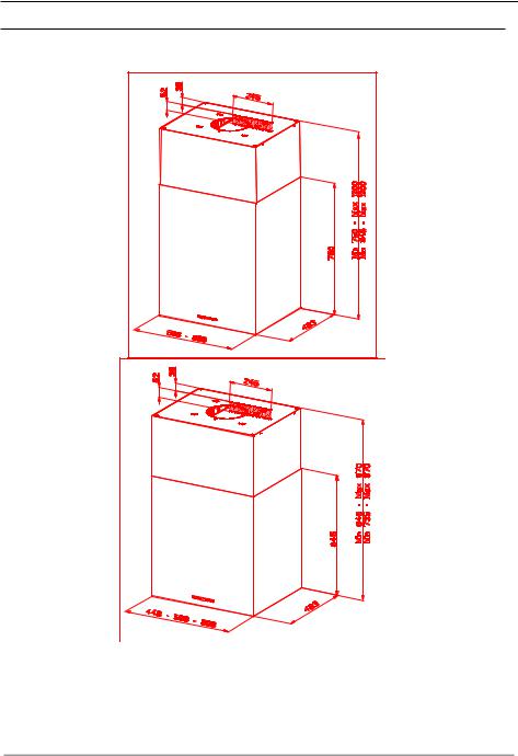
CHARACTERISTICS
Dimensions
The dimensions depend on the cho
* ** |
* **
* |
|
|
|
Dimensions of the hood in ductin |
|||
** |
Dimensions of the hood in recyc |
||
EN |
|
1 |
|
10 |

|
|
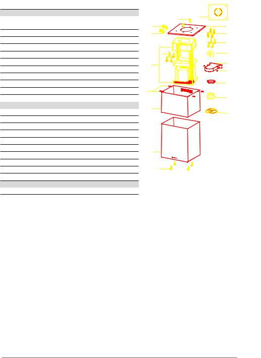
Components |
|
|
|
|
Ref. |
|
Q.ty Product |
Components |
21 |
|
|
1 |
1 |
Hood Body, |
completre, |
with:12w |
Controls, |
Ligh |
|
Filters |
|
23 |
26 |
|
|
2 |
1 |
|
Upper |
Chimney |
|
22 |
|
|
|
|
|
11 |
||||
|
|
|
|
|
|
|
|
|
||||||||
7.1 |
1 |
|
Telescopic |
frametincompletgof: e |
|
with |
|
12h |
||||||||
|
|
extractor, |
||||||||||||||
7.1a 1 |
|
Upper |
frame |
|
|
|
7.1a |
|
|
|
|
|
||||
|
|
|
|
12g |
|
|
|
|
13 |
|||||||
7.1b 1 |
|
Lower |
frame |
|
|
|
|
|
|
|
||||||
|
|
|
|
|
|
|
|
|
|
|||||||
|
|
|
|
|
|
|
|
|
|
7.1 |
|
|
|
|
15 |
|
9 |
1 |
|
Reducer Flange |
ø |
mm |
(Optional) |
||||||||||
|
150-120 |
|||||||||||||||
13 |
1 |
|
Gasket |
|
|
|
|
|
|
|
|
|
|
24 |
||
|
|
|
|
|
|
|
|
|
|
|
|
|||||
14 |
1 |
|
Hood |
Body |
Air |
Outlet |
Extension |
Piece |
||||||||
15 |
1 |
|
Air |
|
Outlet |
Connection |
7.1b |
|
|
|
|
14 |
||||
|
|
|
|
|
|
|
|
|||||||||
25 |
2 |
|
Pipe |
clamps |
|
|
12c |
|
|
|
|
|
|
|||
|
|
|
|
|
|
|
|
|
|
|||||||
26 |
1 |
|
Fixing |
Part |
of the upper |
Chimney |
9 |
|||||||||
Ref. |
Q.ty |
Installation |
Component2 |
s |
|
|
|
|||||||||
11 |
4 |
|
Wall |
Plugs |
ø |
10 |
|
|
|
|
|
|
25 |
|||
|
|
|
|
|
|
|
|
|||||||||
12c |
4 |
|
Screws |
2,9 |
x |
9,5 |
|
|
|
|
|
|
|
|||
12f |
4 |
|
Screws |
M6 |
x |
15 |
|
|
|
|
|
|
|
|
||
12g |
4 |
|
Screws |
M6 |
x |
80 |
|
|
|
|
|
|
|
|
||
12h |
4 |
|
Screws |
5,2 |
x |
70 |
|
|
|
|
|
|
|
|||
12w |
2 |
|
Screws |
M3 |
x |
8 |
|
1 |
|
|
|
|
|
|
||
21 |
1 |
|
Drilling template |
|
|
|
|
|
|
|||||||
22 |
4 |
|
6.4 |
|
mm int. dia |
washers |
|
|
|
|
|
|||||
23 |
4 |
|
M6 |
nuts |
|
|
|
|
12f |
|
|
|
|
|
||
|
|
|
|
|
|
|
|
|
|
|
||||||
24 |
2 |
|
Fixing knobs for the air outlet connectio |
|||||||||||||
|
Q.ty |
Documentation |
|
|
|
|
|
|
|
|
||||||
|
1 |
|
Instruction Manual |
|
|
|
|
|
|
|||||||
EN |
|
1 |
|
11 |
INSTALLATION
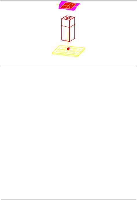
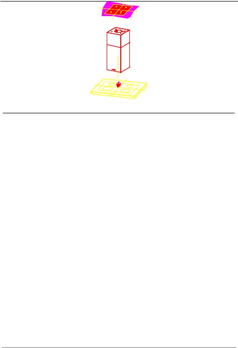
Drilling the Ceiling/shelf and
DRILLING THE CEILING/SHELF
•Use a plumb line to mark the centre of the hob on the ceiling/support shelf.
•Place the drilling template 21 provided on the ceiling/support shelf, making sure that the template is in the correct position by lining up the axes of the template with those of the hob.
•Mark the centres of the holes in the template.
•Drill the holes at the points marked:
•For concrete ceilings, drill for plugs appropriate to the screw size.
•For hollow brick ceilings with wall thickness of 20 mm: drill ø 10 mm(immediately insert the Dowels 11 supplied).
•For wooden beam ceilings, drill according to the wood screws used.
•For wooden shelf, drill ø 7 mm.
•For the power supply cable feed, drill ø 10 mm.
•For the air outlet (Ducted Version), drill according to the diameter of the external air exhaust duct connection.
•Insert two screws of the following type, crossing them and leaving 4-5 mm from the ceiling:
•For concrete ceilings, use the appropriate plugs for the screw size (not provided).
•for Cavity ceiling with inner space, with wall thickness of approx. 20 mm, Screws 12h, supplied.
•For wooden beam ceilings, use 4 wood screws (not provided).
•For wooden shelf, use 4 screws 12g with washers 22 and nuts 23, provided.
EN |
|
1 |
|
12 |

|
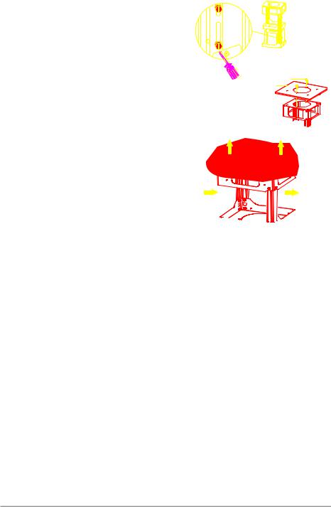
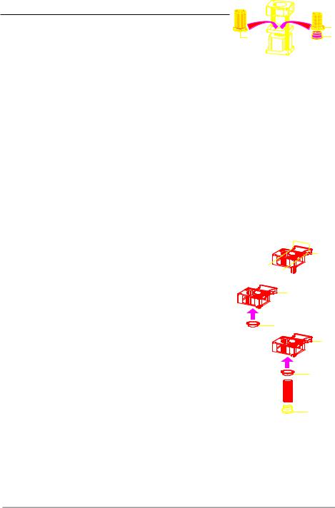
FIXING THE |
FRAME |
|
If you wish to adjust the height of the frame, |
proceed |
|
|
as follows: |
|
|
|
• |
Unfasten the metric screws joining the two columns, |
|
|
|
located at the sides of the frame. |
|
|
• Adjust the frame to the height required, then |
|
||
• |
replace all the screws removed as above. |
|
12w |
Fix the Fixing Part of the Upper Chimney 26 to the |
26 |
||
|
hanging kit using the 2 screws 12w (M3 x 8). |
|
|
• |
Lift up the frame, fit the frame slots onto the screws |
|
|
|
up to the slot end positions. |
|
|
•Tighten the two screws and fasten the other two screws provided; before locking the screws com-
pletely, it is possible to adjust the frame by turning it,
making sure that the screws do not come out of their |
1 |
1 |
|
|
|
housing in the adjustment slot. |
|
|
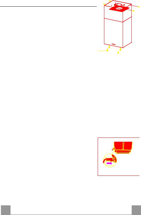
• It is now possible to place and tighten the 4 safety |
|
|
screws, Proceed as follows: |
|
|
• drill the ceiling with a 10 mm ø bit taking as refer- |
2 |
2 |
ence the holes of the side parts of the upper chimney fixing part.
•insert the 4 dowels (provided).
•insert the washers (provided) to the screws and tighten the screws
•The Frame must be securely fastened so as to support both the weight of the Hood and the stress caused by occasional axial pressure against the fitted Appliance. After fixing, make sure that the base is stable even when the Frame is subjected to lateral stress.
•If the Ceiling is not strong enough in the area where the hood is to be fixed, the Installer must strengthen the area using suitable plates and counterplates anchored to resistant structures.
EN |
|
1 |
|
13 |

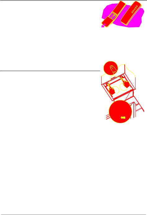
Ducted version air exhausø 150 t systeø 120 m C
When installing the ducted version, connect the hood to the  chimney using either a flexible or rigid pipe ø 150 or 120 mm, 25 the choice of which is left to the installer.
•To install a ø 120 mm air exhaust connection, insert the reducer flange 9 on the hood body outlet.
•Fix the pipe using the pipe clamps 25 provided.
•Remove any activated charcoal filters.
25
9
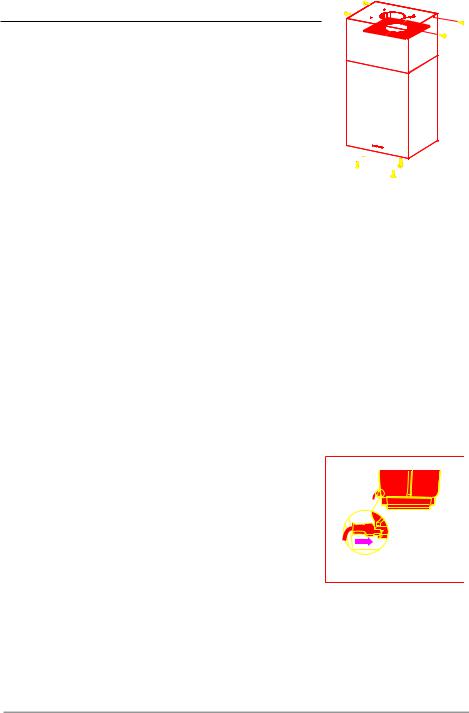
RECIRCULATION VERSION AIR OUTLE24 T
• Insert the reducer flange 9 on the air outlet of the extractor. |
15 |
•Attach the adhesive Novastik gasket 13 to the air outlet connection 15 and fix this to the upper frame using the 2 knobs 24.
•Fix the air outlet connection extension piece 14 to the air outlet
connection 15. |
15 |
• Connect the hood air outlet to the flange in the lower part of |
|
the junction using a rigid or flexible ø 120 tube (by installer’s |
|
choice). |
14 |
15
14
9
EN |
|
1 |
|
14 |
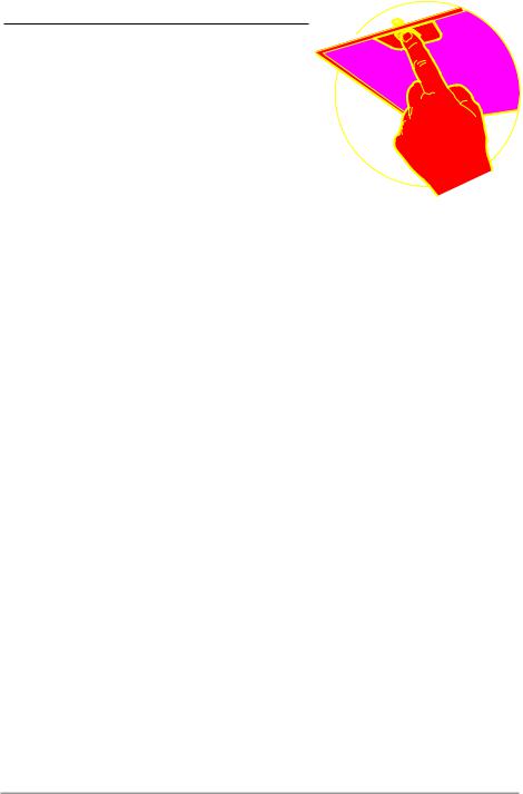
Flue assembly - Mounting the 12chood
• Insert the upper duct and fix it on the top of the upper duct connection using the 12c screws (2.9 x 9.5) supplied with the appliance.
Recirculation version
•It is necessary to make sure that the air outlet connection 15 is placed correctly so that the air outlet grid in it corresponds to that of the chimney.
•If the grids of the two parts are not corresponding to each other, it will be necessary to remove the chimney and to adjust
the position of the air outlet connection 15, and at last to as- 12f 
 sembly the parts again by following the earlier indications.

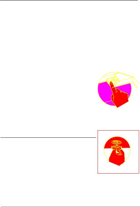
Before fixing the hood body to the frame:
•Open the suction panel by turning the specific knob.
•Disconnect the panel from the hood canopy by sliding the fixing pin lever.
•Remove the grease filters from the hood body.
•Remove any activated charcoal filters.
•From below, use the 4 screws 12f (M6 x 10) provided to fix the hood body to the frame.
ELECTRICAL CONNECTION
• Connect the Hood to the mains power supply, inserting a two-
pole cut-out switch with contact aperture of at least 3 mm along the line.
• Pull the Comfort Panel to open it, ensure that the supply cable
connector is properly inserted into the Suction device socket
• Join the connectors.
•Install the odour filter and the charcoal filter in case the hood is to be used in recycling version.
•Install the grease filter again, and successively the suction panel.
EN |
|
1 |
|
15 |
USE
|
|
|
|
|
|
|
|
|
|
|
|
|
|
|
|
|
|
A |
|
B |
|
C D |
E F G H |
||||||||||||
|
|
|
|
|
|
|
|
|
|
|
|
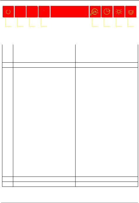
Control board |
|||||
Key |
Function |
Display |
|||||||||||||||
A |
Switches the extractor motor on and off at the |
Indicates the selected speed. |
|||||||||||||||
|
|
|
latest |
selected speed |
|
|
|
|
|
||||||||
B |
Decreases the suction speed. |
|
|
|
|
|
|||||||||||
CIncreases the suction speed.
D |
By pressing this key it is possible to activate |
HI appears. The spot down on the right side |
|
the intensive speed from any previously se- |
flashes once a second. |
|
lected speed. The intensive speed can be acti- |
|
|
vated even when the motor is OFF. This speed |
|
|
has been timed at 10 minutes. After that time |
|
|
the system activates automatically the latest |
|
|
selected speed. This function is suitable for |
|
|
cooking conditions when vapours and smells |
|
|
are of the utmost emission. |
|
E |
By pressing this key it is possible to set up the |
Indicates the 24-function. The spot down on |
|
motor to a suction speed at 100 m3/h lasting 10 |
the right side flashes and the motor is on. |
|
minutes every hour. After this the motor |
Once the process is finished the previous indi- |
|
switches off automatically. |
|
|
cation disappears: |
|
|
When the filter saturation is going on it is pos- |
|
|
FF Indicates that the metal grease filters |
|
|
sible to reset the alarm by pressing this key for |
saturation alarm has been triggered, and |
|
about 3 seconds. The indication is visible only |
|
|
the filters need to be washed. The alarm |
|
|
when the motor is off. |
is triggered after 100 working hours. |
|
|
EF Indicates that the charcoal filter satura- |
|
|
tion alarm has been triggered, and the fil- |
|
|
ter has to be replaced; the metal grease |
|
|
filters must also be washed. The charcoal |
|
|
filter is triggered after 200 working hours. |
F |
By pressing this key it is possible to set the |
Indicates alternately the selected speed of the |
|
delayed shutdown of the appliance to 30 min- |
hood and the time left before the hood shut- |
|
utes. This function is suitable for a complete |
down. The spot down on the right side flashes. |
|
elimination of the residual smells. It can be |
|
|
activated at any position, and it is deactivated |
|
|
by pressing the key again or by switching off |
|
|
the motor. |
|
GTurns light on and off .
HTurns light on and off at reduced intensity.
EN |
|
1 |
|
16 |
MAINTENANCE
REMOTE CONTROL (OPTIO
The appliance can be controlled using a remote control powered by a 1.5 V carbon-zinc alkaline batteries of the standard LR03AAA type.
• Do not place the remote control near to heat sources.
• Used batteries must be disposed of in the proper manner.
Cleaning the Comfor |
anels |
• Pull the Comfort Panel to open it. |
|
• Disconnect the panel from the hood canopy by sliding the fix- |
|
ing pin lever. |
|
• The comfort panel must never be washed in a dishwasher. |
|
•Clean the outside using a damp cloth and neutral liquid detergent.
•Clean the inside as well using a damp cloth and neutral deter-
gent; do not use wet cloths or sponges, or jets of water; do not use abrasive substances.
•When the above operation has been completed, hook the panel back to the hood canopy and close it by turning the knob in the opposite direction.
EN |
|
1 |
|
17 |
Metal grease fi 
Filters can be washed in the dish machine. They need to be washed when FF-sign appears on the display or in 
any case every 2 months, or even more frequently in case of particularly intensive use of the hood.
Alarm reset
•Switch off the hood and the lights. If the 24hfunction has been activated this has to be deactivated.
•Press the E-key till the display is unlit.
Cleaning the filters
•Pull the comfort panels to open them.
•Remove the filters one by one pushing them towards the back side of the hood unit and simultaneously pulling downwards.
•Any kind of bending of the filters has to be avoided when washing them. Before fitting them again into the hood make sure that they are completely dry. (The colour of the filter surface may change throughout the time but this has no influence to the filter efficiency).
•When fitting the filters into the hood pay attention that they are mounted in correct position the handle facing outwards.
•Close the comfort panel.
EN |
|
1 |
|
18 |
Charcoal filter (recycling v
•This filter cannot be washed or regenerated. It must be replaced when the EF appears on the display or at least once every 4 months.
Activation of the alarm signal
•In the recycling version hoods the filter saturation alarm must be activated during the installation or later.
•Switch off the hood and the lights.
•Disconnect the hood from the mains supply.
•When restoring the connection press and hold B-key.
•When releasing the key two rotating rectangles appear on the display.
•Within 3 seconds press the B-key until a flashing confirmation appears on the dispaly:
•2 flashes with EF - charcoal filter saturation alarm ACTIVATED
•1 flash with EF - charcoal filter saturation alarm DEACTIVATED.
REPLACING THE CHARCOAL FILTER
Reset of the alarm signal
•Switch off the hood and the lighting. If the 24h-function has been activated this has to be deactivated.
•Press the E-key until the display is unlit.
Replacing of the filter
•Open the comfort panels pulling them downwards.
•Remove the metal grease filters.
•Remove the saturated charcoal filter by releasing the fixing hooks
•Fit the new filter and fasten it in its correct position.
•Put the metal grease filters in their seats.
•Close the comfort panels.
Lighting LIGHT REPLACEMENT
20 W halogen light.
• Remove the snap-on lamp cover by levering it from under the metal ring, supporting it with one hand.
•Remove the halogen lamp from the lamp holder by pulling gently.
•Replace the lamp with a new one of the same type, making sure that you insert the two pins properly into the housings on the lamp holder.
•Replace the snap-on lamp cover.
EN |
|
1 |
|
19 |
CONSIGLI E SUGGERIMENTI
Questo libretto di peistruzionrpiù versioniper il'usdell'apparecchioè revisto Possibile che sianoelldescrittadotazionesingol,chie particolarnonriguardanid o Vostro apparecchio. 


INSTALLAZIONE |
ziontàpee n |
|||
• |
Il produttore declinrdannqualsiasidovuti |
|||
• |
corretta o non conforme alle rego |
. |
||
La distanza minimaotturdi asicurezze la Ca |
serodei dci |
|||
• |
650 mm. |
|
hettdaa p |
|
Verificare che laquelltensionariportatedi r |
||||
• |
all’interno della Cappa. |
l’imprantisc |
||
Per |
Apparecchi |
in antClassoelettriceIa a oc |
||
• |
un corretto scarico a terra. |
iratparia o |
||
Collegare la Cappaconall’usctubazitonae |
||||
• |
superiore a 120 |
mm. eIlesserp corseilo p |
ssibileonedev. |
|
Non |
collegare |
la Cappfumia prodacottndoti |
oncoe de(cali |
|
• |
daie, |
caminetti, ecc.). |
izzathinoin s |
|
Nel |
caso in cui nelliaala stCanzppa vc |
|||
|
azionati da energia eletiutilizzatorrica(ad iesempidi g |
,pparecchsi dev |
||
|
provvedere ad una aerazionte.Se sufficielacucin |
ambiense |
||
|
sprovvista, praticare un’apl’esterturno,a pechre |
i iconlr |
||
|
chiamo d’aria pulita. |
|
||
USO |
|
|
rglusi |
|
• |
La Cappa è stata progettaodomestaicoesclusi,per |
|||
• |
odori |
della cucina. |
|
|
Non |
fare mai uso improprio della Cappa. |
|
||
•Non lasciare fiammoelaliberCappea ainfortfunzioneeintensit.à sott
•Regolare sempre le fiammevidenteein fumord aitevitaralateraleunea
|
delle stesse rispetto al fondo de |
|
|
entole650 mm min. . |
|||||||
• |
Controllare le surriscaldatfriggitricioduranpot |
|
|
e’usoinfiammarsi:l’olio . |
|||||||
|
|
||||||||||
• |
Non preparare alimentucinai;flambpericolèsotto |
|
d'inol |
cappndioa. da c |
|||||||
|
|||||||||||
|
|
|
|
|
|
|
|
|
|||
• |
Questo apparecchio personnondeve(bambinesserei utiinclizzatusi)ocodna |
||||||||||
|
ridotte capacità psichicheppured,a spersonnrialesenzio amesperienntal,-o |
||||||||||
|
za |
e conoscenza, a |
menistruitoche inonall’ussiano dell’appcontrollarecchtio |
||||||||
• |
da persone responsabili della loro |
|
sicurezza. |
||||||||
I |
bambini devono |
esserrarsei supervisionatchenon giochinipeor coassicun |
|||||||||
|
l’apparecchio. |
|
|
|
|
|
|
|
|
|
|
MANUTENZIONE |
|
manuppa |
||
• |
|
Prima di procedere tenzioneaqualsias,disinsiope |
||
• |
togliendo la spina torelettricegeneraleao speg. |
rut |
||
|
Effettuare una scrupolosnedeia Filtretempeiset |
ntervzio |
||
• |
consigliati. |
|
suffmido |
|
|
Per la pulizia dellicientesuperficeutilizzaridele |
|||
|
detersivo liquido |
neutro. |
|
|
Il |
simbolsulo prodotto o |
sullottaconfeziononon devee indicesserae chconsiderateil prodo |
||
come un normale rifiutortatodomesticoonel punt,moa dieveraccoltesserae appropriatpo |
||||
riciclaggio di appareconicheiatur.Provvedendeelettrichoae smaltiredelettrequesto prodo |
||||
modo appropriato, sialcontribuisciconseguenzeea negativevitaree |
potenziperl’ambiente e |
|||
salute, che potrebberoinadeguatderivaroe dedal unprodottoosmaltiment.Per oinformazioni dettagliate sul riciclaggitattareol’ufficidi questoocomunalemaltiprodotto- , ,ilconservizio loca mento rifiuti o ilo negoziilprodottoin cu.i è stato acquistat
IT |
|
2 |
|
20 |
CARATTERISTICHE
Ingombro
Le dimensioni varianotaa seconda de
* ** |
* **
* Dimensioni per cappa in versione aspiran **Dimensioni per cappa in versione filtran
IT |
|
2 |
|
21 |
|
|
Componenti |
|
|
|
Rif. |
Q.tà |
Componenti di Prodotto |
21 |
||
1 |
1 |
|
|
12w |
|
Corpo Cappa completo di: Comandi, Luce,Gr |
|||||
|
|
Ventilatore, Filtri, Camin23 |
o Inferiore 26 |
||
2 |
1 |
Camino Superiore |
22 |
|
|
11 |
||||||
|
|
|
|
|||||||||
7.1 1 |
Traliccio |
telescopicatoodacomplet:o |
di |
12h |
||||||||
Aspirator |
||||||||||||
7.1a1 |
Traliccio |
superiore |
7.1a |
|
|
|
||||||
12g |
|
|
13 |
|||||||||
7.1b1 |
Traliccio |
inferiore |
|
|
||||||||
|
|
|
|
|||||||||
9 |
1 |
Flangia |
di |
Riduzione |
ø7.1 150-120 |
|
mm |
15 |
||||
|
(Opziona |
|||||||||||
13 |
1 |
Guarnizione |
Adesiva |
Novastik |
|
|
24 |
|||||
|
|
|
||||||||||
14 |
1 |
Flangia per |
Raccordo |
Uscita Aria |
|
|||||||
15 |
1 |
Raccordo |
Uscita |
Aria |
7.1b |
|
|
14 |
||||
|
|
|
|
|||||||||
25 |
2 |
Fascette |
stringitubo 12c |
|
|
|
||||||
26 |
1 |
Attacco |
Camino |
Superiore |
|
|
9 |
|||||
|
|
|
||||||||||
Rif. |
Q.tà |
Componenti |
di Installazion2 |
e |
|
|||||||
11 |
4 |
Tasselli |
ø |
10 |
|
|
|
|
25 |
|||
|
|
|
|
|
||||||||
12c 4 |
Viti |
2,9 |
x |
9,5 |
|
|
|
|
|
|||
12f 4 |
Viti |
M6 |
x |
10 |
|
|
|
|
|
|||
12g 4 |
Viti |
M6 |
x |
80 |
|
|
|
|
|
|||
12h 4 |
Viti |
5,2 |
x |
70 |
|
|
|
|
|
|||
12w 2 |
Viti |
M3 |
x |
8 |
|
|
1 |
|
|
|
||
21 |
1 |
Dima |
di |
foratura |
|
|
|
|
||||
22 |
4 |
Rondelle |
øi |
6,4 |
|
12f |
|
|
|
|||
23 |
4 |
Dadi |
M6 |
|
|
|
|
|
|
|
||
|
|
|
|
|
|
|
|
|||||
24 |
2 |
Pomelli fissaggio Raccordo Uscita Aria |
||||||||||
|
Q.tà |
Documentazione |
|
|
|
|
||||||
|
1 |
Libretto Istruzioni |
|
|
|
|
||||||
IT |
|
2 |
|
22 |
INSTALLAZIONE
Foratura Soffitto/Mensola e Fis
FORATURA SOFFITTO/MENSOLA
•Con l’ausilio di un Filo a piombo riportare sul Soffitto/Mensola di supporto il centro del Piano di Cottura.
•Appoggiare al Soffitto/Mensola la Dima di Foratura 21 in dotazione, facendo coincidere il suo centro al centro proiettato e allineando gli assi della Dima agli assi del Piano di Cottura.
•Segnare i centri dei Fori della Dima.
•Forare i punti seguenti:
•Soffitto in Calcestruzzo massiccio: secondo Tasselli per Calcestruzzo impiegati.
•Soffitto in Laterizio a camera d’aria, con spessore resistente di 20 mm: ø 10 mm (inserire subito i Tasselli 11 in dotazione).
•Soffitto in Travatura di Legno: secondo Viti per Legno impiegate.
•Mensola in Legno: ø 7 mm.
•Passaggio del Cavo elettrico di Alimentazione: ø 10 mm.
•Uscita Aria (Versione Aspirante): secondo diametro del collegamento alla Tubazione di Evacuazione Esterna.
•Avvitare, incrociandole e lasciando 4-5 mm dal soffitto, due viti:
•per Calcestruzzo massiccio, Tasselli per Calcestruzzo, non in dotazione.
•per Laterizio a camera d’aria, con spessore resistente di 20 mm circa, Viti 12h, in dotazione.
•per Travatura di legno, Viti per legno, non in dotazione.
•per Mensola in Legno, viti 12g con Rondelle 22 e Dadi 23, in dotazione.
IT |
|
2 |
|
23 |
FISSAGGIO TRALICCIO
Nel caso in cui si voglia regolare l’altezza del traliccio :
•Svitare le viti che uniscono le due colonne.
•Regolare il traliccio all’altezza desiderata e riavvitare
le viti.
• Unire l’Attacco Camino Superiore 26 al traliccio superiore tramite le 2 Viti 12w (M3 x 8).
• Sollevare il traliccio, incastrare le asole sulle viti e scorrere fino a battuta. A questo punto il traliccio si regge da solo
•Stringere le due viti e avvitare le altre due in dotazione sulla piastra superiore;
Prima di serrare definitivamente le viti è possibile effettuare delle regolazioni spostando il traliccio,facendo attenzione che le viti non escano dalla
1
sede dell’asola di regolazione.
• Ora è possibile avvitare 4 viti di sicurezza,per farlo, procedere come indicato:
• forare con una punta ø 10 il soffitto utilizzando i
|
fori posti sui lati dell’attacco camino superiore. |
2 |
• |
Inserire 4 tasselli in dotazione |
|
• |
Inserire le Rondelle in dotazione nelle viti e serra- |
|
re. |
|
|
•Il fissaggio del Traliccio deve essere sicuro in relazione sia al peso della Cappa sia alle sollecitazioni causate da occasionali spinte laterali all’Apparecchio montato. A fissaggio avvenuto verificare quindi che la base sia stabile anche se il Traliccio è sollecitato a flessione.
•In tutti i casi in cui il Soffitto non fosse sufficientemente robusto sul punto di sospensione, l’Installatore dovrà provvedere a irrobustirlo con opportune piastre e contropiastre ancorate a parti strutturalmente resistenti.
12w
26
1
2
IT |
|
2 |
|
24 |
Connessione Uscita ariø 150a Versionø 120 e As
Per installazione in Versione Aspirante collegare la Cappa alla tubazione di uscita per mezzo di un tubo rigido o flessibile di ø 150 o 120 mm, la cui scelta è lasciata all’installatore.
•Per collegamento con tubo ø 120 mm, inserire la Flangia di riduzione 9 sull’Uscita del Corpo Cappa.
•Fissare il tubo con adeguate fascette stringitubo 25 in dotazione.
•Rimuovere eventuali filtri al carbone attivo.
USCITA ARIA VERSIONE
•Inserire la Flangia di riduzione 9 sull’uscita dell’Aspiratore.
•Attaccare la Guarnizione Adesiva Novastik 13 sul Raccordo Uscita Aria 15 e fissarlo al traliccio superiore tramite i 2 Pomelli 24.
•Attaccare la Flangia Raccordo Uscita Aria 14 al Raccordo U- scita Aria 15.
•Collegare l’uscita aria della cappa con la flangia posta sotto al raccordo per mezzo di un tubo rigido o flessibile ø 120mm, la cui scelta è lasciata all’installatore.
25
25 |
9 |
FILTRANT24E
15
15
14
15
14
9
IT |
|
2 |
|
25 |
Montaggio Camino e Fissaggio Corp12c |
o |
•Inserire il Camino superiore e fissarlo nella parte superiore all’Attacco Camino Superiore con le Viti 12c (2,9 x 9,5) in dotazione.
Versione filtrante
•Assicurarsi che il Raccordo Uscita Aria 15 sia in corrispondenza della Grigliatura del Camino.
•Se così non fosse, rimuovere il camino e aggiustare la posizione del Raccordo Uscita Aria 15; rimontare quindi i particolari come prima descritto.
Prima di fissare il Corpo Cappa al Traliccio: |
12f |
|
•Aprire il pannello aspirante tirandolo.
•Sganciare il pannello dal corpo cappa facendo scorrere l’apposita leva del perno di fissaggio.
•Togliere i Filtri antigrasso dal Corpo Cappa.
•Togliere eventuali Filtri Antiodore al Carbone attivo.
•Fissare quindi dal sotto, con 4 viti 12f in dotazione, il Corpo Cappa al Traliccio predisposto.
CONNESSIONE ELETTRICA
• Collegare la Cappa all’Alimentazione di Rete interponendo un Interruttore bipolare con apertura dei contatti di almeno 3 mm.
•Aprire il Pannello Aspirante e i filtri antigrasso, assicurarsi che il connettore del Cavo di alimentazione sia correttamente inse-
rito nella presa dell’Aspiratore
•Effettuare i collegamenti dei Connettori
•Per la Versione Filtrante montare il Filtro Antiodore al Carbone attivo.
•Rimontare i Filtri Antigrasso e il Pannello Aspirante.
IT
2
26

USO
|
|
|
|
|
|
|
|
|
|
|
|
|
|
|
|
|
|
|
|
|
|
|
|
|
|
A |
|
B |
C |
D |
|
E |
F |
G |
H |
||||||||||||||
|
|
|
|
|
|
|
|
|
|
|
|
|
|
Quadro |
comandi |
|
|
|
|
|
|
|
||
|
|
|
|
|
|
|
|
|
|
|
|
|
|
|
|
|
|
|
|
|
|
|
|
|
|
Tasto |
Funzione |
|
|
|
|
|
|
|
Display |
|
|
|
|
|
|
|
|
||||||
|
|
|
|
|
|
|
|
|
|
|
|
|
|
|
|
|
|
|
|
|
||||
|
A |
Accende e spegne il motore di aspirazione |
Visualizza la velocità impostata |
|
|
|
|
|
|
|
||||||||||||||
|
|
|
|
all’ultima velocità utilizzata. |
|
|
|
|
|
|
|
|
|
|
||||||||||
|
|
|
|
|
|
|
|
|
|
|
|
|
|
|
|
|
|
|
|
|
|
|
||
|
B |
Decrementa la velocità di esercizio. |
|
|
|
|
|
|
|
|
|
|
||||||||||||
|
C |
Incrementa la velocità di esercizio. |
|
|
|
|
|
|
|
|
|
|
||||||||||||
|
|
|
|
|
|
|
|
|
|
|
|
|
|
|
||||||||||
|
D |
Attiva la velocità intensiva da qualsiasi velo- |
Visualizza HI e il punto in basso a destra lam- |
|
||||||||||||||||||||
|
|
|
|
cità anche da motore spento, tale velocità è |
peggia una volta al secondo. |
|
|
|
|
|
|
|
||||||||||||
|
|
|
|
temporizzata a 10 minuti, al termine del tempo |
|
|
|
|
|
|
|
|
|
|
||||||||||
|
|
|
|
il sistema ritorna alla velocità precedentemente |
|
|
|
|
|
|
|
|
|
|
||||||||||
|
|
|
|
impostata. Adatta a fronteggiare le massime |
|
|
|
|
|
|
|
|
|
|
||||||||||
|
|
|
|
emissioni di fumi di cottura. |
|
|
|
|
|
|
|
|
|
|
||||||||||
|
E |
Attiva il motore ad una velocità che consente |
Visualizza 24 e il punto in basso a destra lam- |
|
||||||||||||||||||||
|
|
|
|
un’aspirazione di 100 m3/h per 10 minuti ogni |
peggia, mentre il motore è in funzione |
|
|
|
|
|||||||||||||||
|
|
|
|
ora, terminati il motore si ferma. |
|
|
|
|
|
|
|
|
|
|
||||||||||
|
|
|
|
Con l’allarme filtri in corso premendo il tasto |
Terminata la procedura si spegne la segnala- |
|
||||||||||||||||||
|
|
|
|
per circa 3 secondi si effettua il reset dell’al- |
zione precedentemente visualizzata: |
|
|
|
|
|||||||||||||||
|
|
|
|
larme. Tali segnalazioni sono visibili solo a |
FF segnala la necessità di lavare i filtri anti- |
|
||||||||||||||||||
|
|
|
|
motore spento. |
|
|
|
|
|
|
|
|
grasso metallici. L’allarme entra in fun- |
|
||||||||||
|
|
|
|
|
|
|
|
|
|
|
|
|
|
|
|
zione dopo 100 ore di lavoro effettivo |
|
|||||||
|
|
|
|
|
|
|
|
|
|
|
|
|
|
|
|
della Cappa. |
|
|
|
|
|
|
|
|
|
|
|
|
|
|
|
|
|
|
|
|
|
|
|
EF segnala la necessità di sostituire i filtri al |
|
||||||||
|
|
|
|
|
|
|
|
|
|
|
|
|
|
|
|
carbone attivo e devono anche essere la- |
|
|||||||
|
|
|
|
|
|
|
|
|
|
|
|
|
|
|
|
vati i filtri antigrasso metallici. L’allarme |
|
|||||||
|
|
|
|
|
|
|
|
|
|
|
|
|
|
|
|
entra in funzione dopo 200 ore di lavoro |
|
|||||||
|
|
|
|
|
|
|
|
|
|
|
|
|
|
|
|
effettivo della Cappa. |
|
|
|
|
|
|
|
|
|
F |
Attiva lo spegnimento automatico ritardato di |
Visualizza alternativamente la velocità di eser- |
|
||||||||||||||||||||
|
|
|
|
30’. Adatto per completare l’eliminazione di |
cizio e il tempo rimanente allo spegnimento |
|
|
|
|
|||||||||||||||
|
|
|
|
odori residui. Attivabile da qualsiasi posizione, |
della cappa. Il punto in basso a destra lampeg- |
|
||||||||||||||||||
|
|
|
|
si disattiva premendo il tasto o spegnendo il |
gia. |
|
|
|
|
|
|
|
|
|
||||||||||
|
|
|
|
motore. |
|
|
|
|
|
|
|
|
|
|
|
|
|
|
|
|
|
|||
|
G |
Accende e spegne l’impianto di illuminazione. |
|
|
|
|
|
|
|
|
|
|
||||||||||||
|
|
|
|
|
|
|
|
|
|
|
|
|
|
|
|
|
|
|
|
|
|
|
||
|
H |
Accende e spegne l’impianto di illuminazione |
|
|
|
|
|
|
|
|
|
|
||||||||||||
|
|
|
|
ad intensità ridotta. |
|
|
|
|
|
|
|
|
|
|
|
|
|
|||||||
|
|
|
|
|
|
|
|
|
|
|
|
|
|
|
|
|
|
|
|
|
|
|
|
|
IT |
|
2 |
|
27 |
 Loading...