


Model AA-931
ACTIVE REMOTE CONTROL AUTO SECURITY SYSTEM
WITH BUILT IN 2 - STAGE SHOCK SENSOR
INSTALLATION GUIDE & OWNER’S MANUAL
SYSTÈME ACTIF DE SÉCURITÉ AUTOMOBILE À TÉLÉCOMMANDE
AVEC CAPTEUR DE CHOCS INCORPORÉ À DEUX ÉTAGES
GUIDE D’INSTALLATION ET D’UTILISATION
SISTEMA DE SEGURIDAD ACTIVO PARA AUTOMOVILES A CONTROL REMOTO,
CON DETECTOR DE CHOQUE INCORPORADO DE 2 ETAPAS
GUIA DE INSTALACION Y MANUAL DEL PROPIETARIO

INTRODUCTION
Your new AA -931 Automotive Security System has been designed
with many advanced features that will help to ensure the safety of your
vehicle and it’s contents.
Taking a few moments to read this manual will provide you with
important information required to take advantage of the system’s full
potential.
Performing the installation procedure in the order that the steps are
outlined in this manual should provide you with a quick and trouble free
installation, and remember, if you have questions at any time during the
installation, call:
1 - 800 - 225 - 6074 for the AUDIOVOX INSTALLATION HOT LINE.
TABLE OF CONTENTS
Mounting Components
MountingtheSiren Control Module.........................................................1
-Mounting the Dash L.E.D. Indicator
Wiring the System
-Routing the Wiring Harness
Connecting the RED wire ..................................................................2
-Connecting the BLACK wire
-Connecting the Dark Blue wire
-Connecting the RED wire (from the L.E.D.)
Programming the Keychain Transmitters
CompletingtheInstallation..................................................................3
- Thin BLACK wire
-WHITE Loop wire
-GREEN Loop wire
Adjusting the Sensitivity of the Shock Sensor
Operating the System
-Arming the System
-Protection While the System is Armed
-Disarming the System
-Disarming After Intrusion
DecreasingtheSensitivityofthe Shock Sensor....................................4
Remote Panic Operation
-Emergency By-Pass
-Replacing the Transmitter Battery
Troubleshooting
Schematic ........................................................................................5
INTRODUCTION
Votre nouveau Système de sécurité pour véhicule, Modèle AA-931,
a été conçu avec de nombreuses fonctions incorporant une technique pointue qui vous aideront à assurer la sécurité de votre
véhicule et de son contenu. Les quelques moments que vous
consacrerez à la lecture du présent manuel vous apporteront une
quantité importante de renseignements nécessaires pour tirer le
meilleur partide toutes les possibilités dusystème.Si vous effectuez
l’installation en suivant l’ordre des opérations indiquées dans le
manuel, vous ne devriez rencontrer aucun problème et procéder
rapidement. Souvenez-vous que sivous avez la moindre question à
poser au cours de l’installation, vous pouvez appeler AUDIOVOX
INSTALLATION—LIGNE D’URGENCE au 1-800-225-6074.
TABLE DES MATIÈRES
Montage des composants
Montage du module de commande de la sirène ..........................6
-Montage de l’indicateur D.E.L. du tableau de bord
Câblage du système
-Acheminement du harnais de câblage
Connexion du fil ROUGE .............................................................7
- Connexion du fil NOIR
-Connexion du fil BLEU FONCÉ
- Connexion du fil ROUGE (provenant de la DEL)
Programmation des transmetteurs de porte-clés
Achèvement de l’installation ....................................................8
- Fil NOIR fin
- Fil en boucle BLANC
- Fil en boucle VERT
Réglage de sensibilité du détecteur de vibrations
Fonctionnement du système
- Armement du système
- Protection pendant que le système est armé
-Désarmement du système ..........................................................9
- Désarmement après une intrusion
- Diminution de la sensibilité du détecteur de vibrations par le
transmetteur du porte-clés
- Télécommande du système anti-panique
- Dérivation d'urgence
- Remplacement des piles du transmetteur
Dépannage
Schémas ...................................................................................12
INTRODUCCION
Su nuevo Sistema de Seguridad para Automóviles AA-931 està
diseñado con muchas funciones de avanzada que le ayudarán a
garantizar la seguridad del vehículo y su contenido. Dedique un
tiempo a leer est manual a fin de obtener ínformación importante que
le servirá para aprovechar al máximo la capacidad potencial del
sistema.
Si sigua el procedimiento de instalación en el orden que sedescriben
los pasos en el presente manual, podrárealizar la instalación
rápidamente y sin dificultad alguna, y recurede que en caso de tener
alguna pregunta o duda en cualquíer momento de la instalación,
puede llamar al 1-800-225-6074 que es el teléfono sin cargo de
información sobre instalación de Audiovox.
INDICE
Instalación del los componentes
Instalación del módulo de control de la sirena ..................................11
-Instalación del indicador L.E.D. en el tablero de instrumentos
Cableado del sistema
-Colocación del arnés de cables
ConexióndelcableROJO .................................................................12
-Conexión del cable NEGRO
-Conexión del cable AZUL OSCURO
-Conexión del cable ROJO (del LED)
Programación de los transmisores de llavero
Terminacióndela instalación ...........................................................13
-Cable fino NEGRO
-Cable en bucle BLANCO
-Cable en bucle VERDE
Ajuste de la sensibilidad del detector de choque
Operación de sistema
-Activación del sistema
-Protección mintras el sistema está activado
- Desactivación del sistema
-Desactivación después de una intrusión ........................................14
-Reducción de la sensibilidad del detector de choque por medio del
transmisor de llavero
-Operación a la distancia en caso de emergencia
- Desvío de emergencia
-Cambio de la pila del transmisor
Resolución de problemas
Diagramaesquemático.....................................................................15

MOUNTING THE COMPONENTS
1. Mounting The Siren Control Module
Select a flat, metal surface within the engine compartment, but not on
the engine, for mounting the siren control module. Keep in mind that the
horn end must be facing down to prevent water from entering the
module.
A location on the firewall, which is not easily accessible from underneath the vehicle, is preferred. This location will provide optimum
operation of the shock sensor, and prevent the potential thief from
disconnecting the alarm from below the vehicle.
You should also locate the control module away from hot or moving
components within the engine compartment, and avoid areas where
water will run off or collect during heavy rainstorms.
To mount the siren control module;
A. Secure the module mounting bracket to the selected location using
the (2) 3/4" long screws provided. Carefully drill a 1/8" diameter pilot
hole for starting the screws.
B. In most cases, if the bracket has been secured to a solid metal
surface, you can connect the BLACK wire from the wiring harness
to the siren mounting bolt. Using a 10 mm wrench or socket, secure
the siren module ( and eyelet terminal on the end of the BLACK wire)
to the bracket using the (2) 3/8" long hex head bolts and (2) split lock
washers provided.
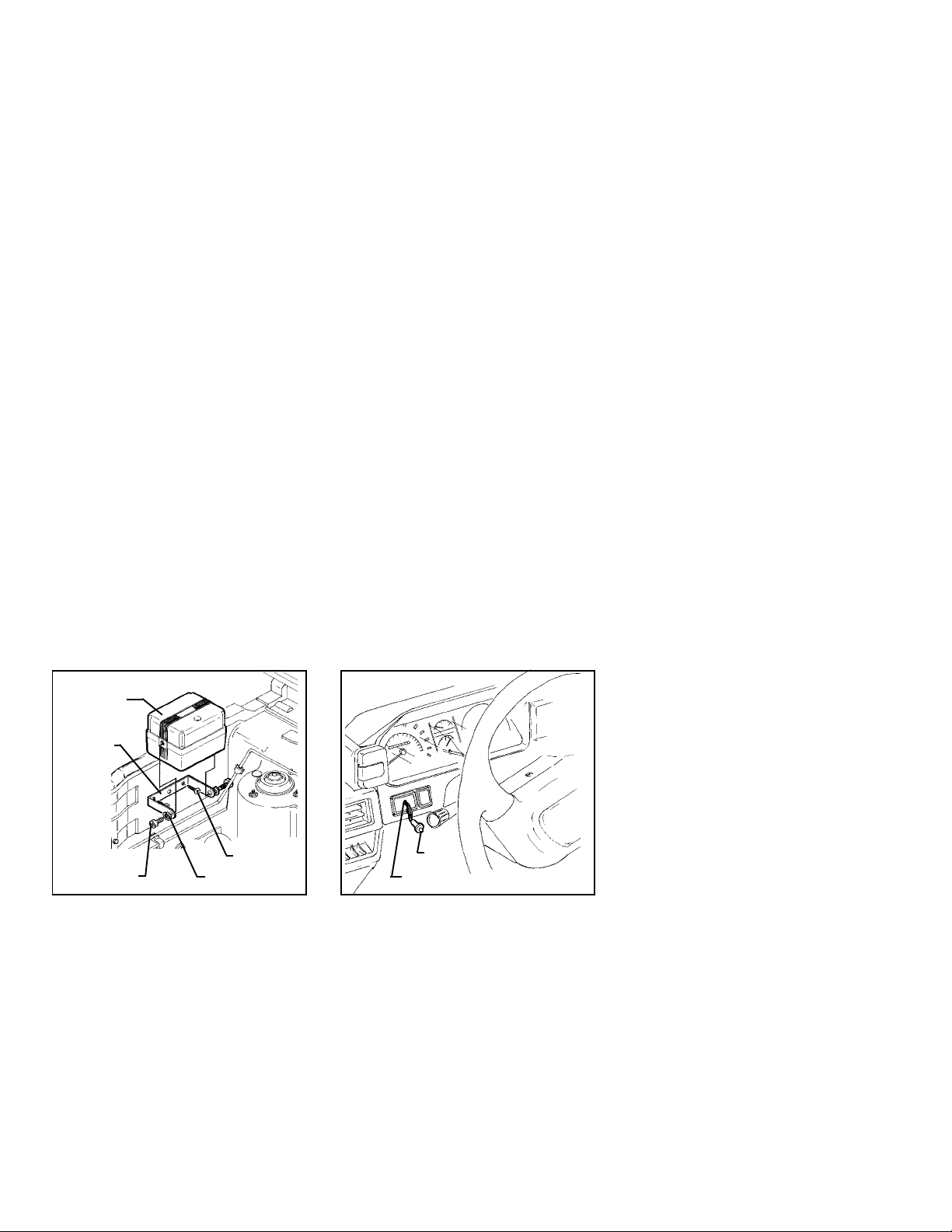
SIREN MODULE
BRACKET
2. Mounting The Dash L.E.D. Indicator
Select an area on the dashboard or center console that will provide the
most visibility from all angles outside the vehicle ( driver’s window,
passenger’s window, rear window, etc. ).
IMPORTANT ! Make sure there is adequate room for the body of the
L.E.D. behind the panel in the selected location. You should also be
sure that the drill will not pierce any wires, or damage other components after passing through the panel. It is always best to remove the
panel from the vehicle before drilling the hole.
To mount the L.E.D.;
A. Drill a 1/4" diameter hole at the selected mounting location.
B. Pass the L.E.D. wires through the hole from the front of the panel,
and press the body of the L.E.D. into the hole until fully seated.
WIRING THE SYSTEM
Making the connections to the vehicle, as described in this wiring
section, may be beyond the technical abilities of the average consumer. If you have any questions with the wiring procedures, please
calla qualified automotive technician, or call the AUDIOVOX HOT LINE
at 1 - 800 - 225 - 6074. Prior to making any connections, a 12 Volt logic
probe should be used to confirm the proper connection point.
IMPORTANT ! The 4 pin white connector on the end of the main
harness that plugs into the siren control module should remain
disconnected during the wiring portion of the installation. Leaving this
disconnected will ensure that the keychain transmitters are properly
programmed later in the installation.
1. Routing The Wiring Harness
The DARK BLUE wire must be routed through the firewall, and into the
passenger compartment of the vehicle, towards the dash L.E.D. In
most cases, the RED wire will also be routed into the passenger
compartment, to the courtesy light fuse. Before proceeding with the
wire routing, verify the location of the courtesy light fuse, as a small
percentage of vehicles locate this fuse in the engine compartment, and
in these cases, it will not be necessary to route the RED wire through
the firewall.
After confirming these component locations, route the DARK BLUE
and RED wires towards their connection points. Caution should be
used when routing wires. Keep wires away from all hot surfaces, and
any moving parts of the vehicle ( radiator fans, accelerator or brake
pedal linkage, etc. ).
When routing wires through the firewall, be sure to pass the wires
through an existing rubber grommet. Failure to do this can result in
damage to wires from sharp metal edges, and an eventual failure of the
security system.
3/8" LG. HEX BOLTS
3/4" LG. SCREWS
SPLIT LOCKWASHER
L.E.D.
DRILL A 1/4" DIAMETER HOLE
Page 1
2. Connecting the RED Wire
Locate the courtesy lamp fuse. Both sides of the fuse will indicate + 12
Volts on the logic probe while the fuse is plugged in. Remove the fuse,
and test the contacts that the fuse plugs into. One of the contacts will
not indicate + 12 Volts. This is where the RED wire will be connected.
Connection Method A;
A. Locate the wire coming from this fuse terminal at the back of the
fusebox.
B. Splice the RED wire from the harness to this wire, and insulate with
electrical tape.
Connection Method B;
A. “ Fuse clip “ terminals, which will plug in with the contacts of the fuse,
are available at most electronics stores. This method of connection
may be easier in some vehicles.
B.Refer to the specific instructions includedwith the fuse clip terminals.
SPLICE INTO WIRE AND WRAP
WITH ELECTRICAL TAPE
FUSE BOX
COURTESY
LIGHT FUSE
FUSE CLIP TERMINAL
(NOT INCLUDED)
RED WIRE
B
RED WIRE
A
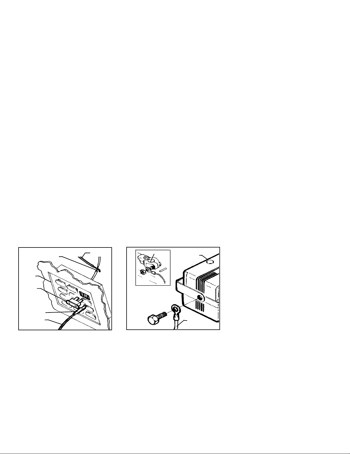
3. Connecting the BLACK Wire
The larger BLACK wire ( not the thin black antenna wire ), should have
been connected to ground during the siren module mounting procedure. If you were unsure of the ground reliability of the siren module
mounting bracket, you can connect the eyelet on the end of the BLACK
wire to any non painted bolt on the firewall or fender, which is threaded
directly into a metal surface of the vehicle.
NEGATIVE TERMINAL
SIREN MODULE
BLACK WIRE
Page 2
4. Connecting the DARK BLUE wire
Connect the DARK BLUE wire from the main harness to the BLUE wire
from the dash mounted L.E.D. Be sure to insulate this connection with
electrical tape.
5. Connecting the RED wire ( From the L.E.D. )
Splice the Red wire from the dash mounted L.E.D. to the larger RED
wirefrom the main harness. Be sureto insulate this splice with electrical
tape.
PROGRAMMING THE KEYCHAIN TRANSMITTERS
The two keychain transmitters that are included with this system are a
“ code learning “ type Radio Frequency transmitter, which simply
means that the siren control module will learn and remember the
individual code number of each transmitter. The siren control module
will learn the individual codes of (2) transmitters only.
IMPORTANT ! Save these programming instructions in a place where
you can easily find them in the future. Whenever the vehicle’s battery
is disconnected for servicing, the transmitters will need to be reprogrammed.
To Program the Transmitters;
A. The main harness connector should be disconnected from the siren
control module at this step of the installation procedure. If it is not,
unplug the connector.
B. Be sure to have both keychain transmitters in hand, then plug the
main harness connector into the siren control module.
C.Press and hold the larger arming button on transmitter number 1 until
the siren sounds one long “ chirp “.
D. Immediately press and hold the larger arming button on transmitter
number 2 until the siren sounds one long “ chirp “.
E. Both transmitters should now be programmed. You can test this by
pressing the arming button on each transmitter, which will result in
theappropriate “ ARMED “ or “ DISARMED “ indicationfrom the siren
module.
IMPORTANT ! If only one transmitter is operating, repeat the programming procedure. Once the harness connector is plugged in, you have
only 15 seconds in which to program both transmitters. This short time
window is required in order to provide a high level of security.

COMPLETING THE INSTALLATION
You will notice (3) additional wires, which come directly out of the
rubber wire exit boot from the siren control module, and are not part of
the main harness. These wires are used to customize the installation,
and are required in some vehicles.
1. Thin BLACK Wire
This is the antenna wire for the receiver that is built into the siren control
module. Fully extend this wire, and route it as high in the engine
compartment as possible, for maximum transmitter range.
2. WHITE Loop Wire
This wire exits the rubber boot, and immediately loops back into the
rubber boot.
Three minutes after the alarm has been armed, the voltage sensing
circuitry becomes active. This voltage sensing monitors the voltage
level of the vehicle, and when it sees a change ( i.e. a door opens, and
the interior light turns on ), the alarm is triggered.
Many vehicles incorporate an electronic cooling fan, which will automatically switch on after the vehicle has been turned off. If this fan
switches on shortly after the alarm has been armed, the system will not
trigger due to the three minute delay.
If your vehicle does not have an electronic cooling fan which turns on
after the vehicle has been turned off, you may elect to by pass the three
minute arming delay of the voltage sense circuit. The system can be
modified so that six seconds after arming, the voltage sensing circuitry
becomes active. The three minute time delay can be eliminated by
cutting the WHITE wire loop. After cutting the WHITE wire loop,
individually insulate both ends of the wire with electrical tape.
Do not cut this loop if your vehicle is equipped with an electronic cooling
fan, as you will experience false alarms.
3. GREEN Loop Wire
This wire exits the rubber boot, and immediately loops back into the
rubber boot.
Cutting this wire will eliminate the voltage sensing feature of the alarm.
When this wire is cut, opening the doors will not trigger the system.
This loop wire should be cut only if you want to protect the vehicle from
sudden impacts to the glass or body panels, but do not want the alarm
to trigger when a door has been opened.
ADJUSTING THE SENSITIVITY OF THE SHOCK SENSOR
The purpose of a shock detector is to “sense” strong impacts to the
vehicle’s glass and body panels, but ignore light bumps to the vehicle.
This alarm is programmed to report these impacts in two ways.
A lighter impact will cause the alarm to sound a series of short “chirps”,
warning anyone tampering with the vehicle to stop immediately.
A more forceful impact will cause the alarm to sound for it’s full 60
second cycle, informing you that a serious violation attempt has
occurred.
IMPORTANT ! Setting the sensitivity of the shock sensor too high will
cause false alarms. A substantial amount of force is required to
actually break automotive glass, and the shock sensor should be set
accordingly.
Before proceeding with the adjustment, verify that all screws securing
the siren control module to the bracket, and securing the bracket to the
vehicle, are securely tightened.
To adjust the shock sensor;
A. Locate and remove the small rubber plug on the back of the siren
control module.
B. Gently turn the adjustment screw fully counter - clockwise, then
clockwise approximately 1/8 of a turn. Do not over turn this screw,
as maximum rotation is approximately 270°. You should stop
applying pressure as soon as you feel a slight amount of resistance.
C. Close the hood, arm the alarm ( “ 1 CHIRP “ ), and allow six seconds
for the shock sensor to stabilize.
D. Firmly strike the front bumper of the vehicle with the side of a closed
fist, considering the amount of force required to break a window.
CAUTION ! Never perform this test on the vehicle’s glass, as you may
break a window.
E. If the alarm did not sound, or if only the warning chirps were
activated, then the sensitivity will need to be increased. Disarm the
alarm, and open the hood to gain access to the siren control module.
F. Gently turn the adjustment screw approximately 1/8 turn clockwise
( increasing sensitivity ), and repeat the test.
G. Repeat this procedure until a firm strike causes the alarm to trigger,
and a less forceful impact causes the alarm to sound the warning
chirps.
H. When the adjustment is set, replace the rubber plug on the back of
the siren module.
Page 3
OPERATING THE SYSTEM
1. Arming the System
A. Exit the vehicle, and close and lock all doors.
B. Press and release the larger arming button on the keychain
transmitter. The system will respond with one single chirp.
C. The red dash mounted L.E.D. will begin to flash, and after approxi-
mately six seconds, the shock sensing feature of the system will be
activated. The voltage sensing circuit will begin its countdown, and
after approximately three minutes, opening a light activated door will
trigger the alarm.
IMPORTANT ! If the WHITE loop wire was cut during the installation
procedure, the voltage sensing feature of the alarm will become active
six seconds after arming the system ( see COMPLETING THE INSTALLATION, WHITE Loop Wire ). You will not need to wait the three
minutes before opening a door will cause the alarm to trigger.
2. Protection While the System is Armed
A. Opening a door ( or any light activated entry point ), will cause the
alarm to immediately sound for the complete 60 second alarm cycle.
B. While the system is armed, the red dash mounted L.E.D. will
constantly flash, discouraging any would be thieves.
C. Any light impact to the vehicle glass or body panels will cause the
system to immediately sound the warning chirps, discouraging any
further attempts to enter the vehicle.
D. Any forceful impact to the vehicle will cause the system to immedi-
ately trigger for the complete 60 second alarm cycle. At the end of
the cycle, the alarm will re - arm itself, and resume monitoring the
vehicle.
3. Disarming the System
A. When you return to the vehicle, press and release the larger arming
button on the keychain transmitter. The system will respond with two
chirps.
B. The red dash mounted L.E.D. will turn off, indicating that the system
is disarmed, and it is safe to enter the vehicle.
4. Disarming After an Intrusion
When disarming, if the system responds with four chirps, you are being
alerted that the alarm was triggered during your absence. Additionally,
the red dash mounted L.E.D. will blink 3 times .. pause .. blink 3 times
.. etc., to provide an added visual indication that the alarm had been
triggered.

To clear the L.E.D. intrusion flash pattern,
A. Arm the system, then immediately disarm the system.
B. The L.E.D. will turn off, and the system will be reset for normal
operation.
5. Decreasing the Sensitivity of the Shock Sensor via the
Keychain Transmitter
There may be some circumstances when you will want to arm the
system, but decrease the sensitivity of the shock sensor, or simply turn
the shock sensor off. This feature can be useful during extreme
thunderstorms, or when parking on or near heavy construction sites.
To arm and decrease shock sensitivity,
A. Follow the normal arming procedure by pressing the larger button
on the keychain transmitter.
B. Immediately after arming, press and release the smaller button on
the keychain transmitter.
C. In approximately five seconds, the siren will sound one long chirp,
indicating that the sensitivity of the shock sensor has been reduced
30 percent.
To arm and turn the shock sensor off,
A. Follow the normal arming procedure by pressing the larger button on
the keychain transmitter.
B. Immediately after arming, press and release the smaller button on
the keychain transmitter two times.
C. In approximately five seconds, the siren will sound one short chirp,
followed by one long chirp, indicating that the shock sensor has
been turned off.
IMPORTANT ! Any time the shock sensor has been adjusted using the
keychain transmitter, disarming then re arming the system will return
the shock sensor to its normal operating sensitivity.
6. Remote Panic Operation
The alarm can be activated via the keychain transmitter to draw
attention to your vehicle during an emergency situation.
To activate the panic feature;
A. Press and hold the larger button on the keychain transmitter for 3
seconds.
B. The alarm will sound, and continue to sound for 60 seconds.
C. To silence the alarm before the 60 second shutdown, press and
release the larger button on the keychain transmitter.
WARNING ! In most areas, it is illegal to activate the alarm while the
vehicle is moving. For the safety of your passengers and other
motorists, do not activate the alarm while your vehicle is in motion.
7. Emergency By - Pass
If you lose or misplace your transmitter, or the transmitter fails to disarm
the system due to poor battery condition, you must by - pass the
security system.
To do this;
A. Open the driver’s door. The alarm will sound.
B. Pull the hood release lever, and open the hood.
C. Locate the RED wire from the siren control module, and remove the
fuse from the fuseholder.
D. Do not replace this fuse until your transmitters are repaired or
replaced.
E. When re - inserting the fuse, you will need to reprogram your
transmitters. ( refer to “ PROGRAMMING THE KEYCHAIN TRANSMITTERS ).
8. Replacing the Transmitter Battery
The keychain transmitters have a small, red L.E.D. visible through the
topcover. This L.E.D. can be used to indicate battery condition. You will
also notice a decrease in effective transmitter range as the battery
deteriorates.
The replacement battery must be a 12 volt type GP23A or equivalent.
To replace the transmitter battery;
A. Remove the small phillips head screw from the bottom of the
transmitter, and carefully pry the top cover ( button side ) away from
the transmitter.
B. Remove the discharged battery, making note of the orientation of the
+ and - contacts, and dispose of properly.
C. Install the new battery, taking care to place the + and - contacts in
the correct position.
D. Replace the transmitter cover, taking care not to damage the L.E.D.
or switches on the circuit board.
E. Replace the small phillips head screw through the bottom of the
transmitter.
Page 4
TROUBLESHOOTING :
Symptom : The transmitters will not program to the siren control
module.
Check :
A. Verify that the fuse in the red wire from the siren
control module is in good condition. Replace it if it is
blown.
B. Verify that the connections of the red and black wires
have been made according to the wiring section of
this manual.
C. You have only 15 seconds after applying power to the
siren control module in which to program both transmitters.
Symptom : The alarm will not arm and disarm using the keychain
transmitter.
Check :
A. Verify the transmitter battery is in good condition. Try
both transmitters. Replace the transmitter battery if
necessary.
B. Verify that the transmitter is programmed to the siren
control module. When the vehicle’s battery is disconnected, or when power is removed from the siren
control module, the transmitters need to be re programmed. Follow the programming instructions in
this manual.
C. Verify that the fuse in the red wire from the siren
control module is in good condition. Replace it if it is
blown.
D. Verify that the connections of the red and black wires
have been made according to the wiring section of
this manual.

SIREN MODULE
GREEN AND WHITE
WIRE LOOPS
THIN BLACK ANTENNA WIRE
BLACK
GROUND
L.E.D.
Printed in Taiwan Audiovox Corp., 150 Marcus Blvd. Hauppauge, N.Y. 11788 Form No. 128-4434
DARK BLUE
BLUE
RED
Page 5
RED
SPLICE
TO +12V CONSTANT
IN VEHICLE'S
FUSEBOX
MONTAGE DES COMPOSANTS
1. Montage du module de commande de la sirène
Choisir une surface métallique plane à l’intérieur du compartiment
du moteur, mais qui ne soit pas sur le moteur, pour monter le module
de commande de la sirène. Il faut garder à l’esprit que le côté de
l’avertisseur doit être tourné vers le bas pour empêcher que l’eau ne
pénètre dans le module.
Un emplacement sur la cloison pare-feu à laquelle on ne peut
accéder depuis le dessous du véhicule est préférable. Un tel
emplacement fournit des conditions de fonctionnement optimales
au capteur de vibrations et empêche tout malfaiteur éventuel de
déconnecter l’alarme par le dessous du véhicule.
Il faut aussi que le module de commande soit placé aussi loin que
possible des composants chauds ou mobiles à l’intérieur du
compartiment du moteur, et il faut également éviter les zones où
l’eau risque de couler ou de s’accumuler pendant les gros orages.
Pour monter le module de commande de la sirène:
A.Fixer la patte de support de montage du module à l’emplacement
choisi à l’aide des deux (2) vis de 1,9 cm (3/4") de long fournies
avec le module. Il faut percer avec précautions un trou pilote de
0,32 cm (1/8") de diamètre pour amorcer les vis.
B.Dans la plupart des cas, lorsque la patte de support a été fixée sur
une surface métallique solide, on peut connecter le fil NOIR
sortant du faisceau de conducteurs au boulon de montage de la
sirène. Avec une clé ou une douille de 10 mm, fixer le module de
la sirène (et la borne en illet située à l’extrémité du fil NOIR) au
support à l’aide des deux (2) boulons à tête hexagonale de 0,95
cm (3/8") de long et des deux (2) rondelles de blocage fendues
fournis avec le module.
MODULE
DE LA SIRÈNE
SUPPORT
VIS DE 1,9 CM
BOULONS À TÊTE
HEXAGONALE DE
0, 95 (3/8") DE LONG
(3/4") DE LONG
RONDEL LE DE
BLOCAGE FENDUE
3.Montage de l’indicateur D.E.L. du tableau de bord
Choisir l’emplacement sur le tableau de bord ou au centre de la
console qui sera le plus visible de l’extérieur du véhicule, à partir de
touslesanglespossibles(fenêtreduconducteur, fenêtres passagers,
lunette arrière, etc.).
ATTENTION! Il faut s’assurer qu’il existe suffisamment de place
pour le corps de la D.E.L. derrière le panneau de montage à
l’emplacement choisi. Il faut également veiller à ce que la perçeuse
ne sectionne aucun fil et n’endommage aucun composant après
avoir percé le panneau. Il est toujours recommandé d’enlever le
panneau du véhicule avant de percer le trou.
Pour monter la D.E.L., il faut:
A.Percer un trou de 0,64 cm (1/4") de diamètre à l’emplacement
choisi pour l’installation.
B.Faire passer les fils de la D.E.L. à travers le trou à partir de l’avant
du panneau,et enfoncer le corps de la D.E.L. dans le trou jusqu’à
ce que celle-ci soit bien assise.
D.E.L.
PERCER UN TROU DE 0,64 CM
(1/4") DE DIAMÈTRE
Page 6
CÂBLAGE DU SYSTÈME
Il est possible que la réalisation des connexions au véhicule, telles
que décrites dans la présente section relative au câblage, dépasse
leniveaudesconnaissances techniques d’un consommateur moyen.
Si vous avez la moindre question à poser au sujet des méthodes de
câblage, veuillez appeler un électricien spécialiste des circuits
électriques sur véhicules, ou bien encore, appelez AUDIOVOXURGENCES au 1-800-225-6074. Avant d’effectuer une connexion
quelconque, il faut utiliser une sonde logique de 12 volts pour
confirmer que la tension soit correcte au point de connexion.
ATTENTION! Leconnecteur blanc à 4 broches situé à l’extrémité du
faisceau de conducteurs principal, qui se branche dans le module de
commande de la sirène, doit rester déconnecté pendant l’opération
de câblage de l’installation. En laissant ce connecteur déconnecté,
onassurequelestransmetteursduporte-clésserontconvenablement
programmés, plus tard au cours de l’installation.
1.Acheminement du harnais de câblage
Le fil BLEU FONCÉ doit être acheminé à travers la cloison pare-feu et
jusque dans l’habitacle du véhicule, vers la DEL du tableau de bord.
Dans la plupart des cas, le fil ROUGE sera aussi acheminé dans
l’habitacle, jusqu’au fusible de l’éclairage intérieur. Avant de procéder
àl’acheminementdesfils, vérifier l’emplacement du fusible de l’éclairage
intérieur car, sur un petit nombre de véhicules, ce fusible est situé dans
le compartiment-moteur et, dans ce cas, il ne sera pas nécessaire
d’acheminer le fil ROUGE à travers la cloison pare-feu.
Après avoir confirmé l’emplacement de ces composants, acheminer le
fil BLEU FONCÉ et le fil ROUGE vers leurs points de connexion. Il faut
procéder prudemment en acheminant ces fils. Les fils doivent être
tenus à l’écart de toutes les surfaces chaudes et de toute pièce mobile
duvéhicule(ventilateursde radiateur, tringlerie de pédale d’accélérateur
ou de frein, etc.)
En acheminant les fils à travers la cloison pare-feu, s’assurer de passer
les fils à travers une virole en caoutchouc existante. Si ce n’est pas fait,
il peut y avoir endommagement des fils au contact avec des arêtes
métalliques vives, et il peut y avoir une éventuelle défaillance du
système de sécurité.

2. Connexion du fil ROUGE
Repérer le fusible des lampes de service. Les deux côtés du fusible
doivent indiquer +12 volts sur la sonde logique pendant que le
fusible est enfiché. Enlever le fusible et tester les contacts dans
lesquels le fusible s’enfiche. L’un des contacts n’indiquera pas +12
volts. Ceci est le point où le fil ROUGE doit être connecté.
Connexion par la méthode A:
A.Repérer le fil sortant de cette borne de fusible, à l’arrière du coffret
à fusibles.
B.Connecter le fil ROUGE du faisceau à ce conducteur par une
épissure qu’il faut protéger avec du ruban isolant électrique.
Connexion par la méthode B:
A.On peut se procurer dans presque tous les magasins de matériel
électronique des bornes en “douilles de fusible”, qui s’enfichent
dans les contacts de fusible. Cette méthode de connexion peut
être plus facile dans certains véhicules.
B.Consulter les instructions spécifiques comprises dans le paquet
de bornes en douilles de fusible.
CONNECTER AU FIL PAR UNE ÉPISSURE ET
ENROULER DU RUBAN ISOLANT
ÉLECTRIQUE AUTOUR DE LA
CONNEXION
COFFRET
ÀFUSIBLES
FUSIBLE
DESLAMPES DE
SERVICE (PORTES,
PLAFONNIER)
BORNE EN DOUILLE
DE FUSIBLE
(NON COMPRISE)
FILROUGE
B
FIL ROUGE
A
3. Connexion du fil NOIR
Le fil NOIR le plus gros (et non le fil noir mince servant de fil
d’antenne) doit avoir été connecté à la masse au cours du montage
du module de commande de la sirène. Si vous n’avez pas confiance
dans la mise à la masse effectuée sur la patte de support de fixation
du module de sirène, vous pouvez connecter l’ illet situé à l’extrémité
du fil NOIR à l’un quelconque des boulons non peints situés dans la
cloison pare-feu ou l’aile qui sont vissés directement dans les filets
d’une plaque métallique du véhicule.
BORNE NÉGATIVE
MODULE DE
SIRÈNE
FIL NOIR
Page 7
4.Raccordement du fil BLEU FONCÉ
Raccorder le fil BLEU FONCÉ provenant du harnais principal au fil
BLEU provenant de la DEL montée sur tableau de bord. S’assurer
d’isoler cette connexion à l’aide de ruban électrique.
5. Raccordement du fil ROUGE (provenant de la DEL)
Épisser le fil rouge provenant de la DEL montée sur tableau de bord au
fil ROUGE plus gros provenant du harnais principal. S’assurer d’isoler
cette épissure à l’aide de ruban électrique.
PROGRAMMATIONDESTRANSMETTEURSDEPORTECLÉS
Les deux transmetteurs de porte-clés compris avec le présent
système sont des transmetteurs de type à radiofréquence
programmables, ce qui signifie simplement que le module de
commande de la sirène peut sauvegarder en mémoire et réutiliser le
numéro de code individuel de chaque transmetteur. Le module de
commande de la sirène enregistre les codes individuels de deux (2)
transmetteurs seulement.
ATTENTION! Conserverlesinstructionsdeprogrammationsuivantes
en lieu sûr et facile d’accès pour pouvoir les utiliser à l’avenir.
Chaque fois que la batterie du véhicule est déconnectée à l’occasion
d’une séance d’entretien ou de maintenance, il faut reprogrammer
les transmetteurs.
Comment programmer les transmetteurs:
A.Le connecteur du faisceau principal doit être déconnecté du
module de commande de la sirène à ce point des opérations
d’installation. S’il ne l’est pas, il faut le déconnecter.
B.Vérifier que les deux transmetteurs de porte-clés sont dans votre
main, puis enficher le connecteur du faisceau principal dans le
module de commande de la sirène.
C.Appuyer sur le gros bouton d’armement du transmetteur Nº 1 et
maintenir le bouton enfoncé jusqu’à ce que la sirène émette un
son long.
D.Appuyer immédiatement sur le gros bouton d’armement du
transmetteur Nº 2 et le maintenir enfoncé jusqu’à ce que la sirène
émette un son long.
E.Les deux transmetteurs doivent alors être programmés. On peut
faire un test de vérification en appuyant sur le bouton d’armement
de chaque transmetteur, ce qui doit fournir une indication de
système “ARMÉ” ou “DÉSARMÉ” en provenance du module de la
sirène.
ATTENTION! Si un seul transmetteur fonctionne, il faut recommencer
l’opérationdeprogrammation.Unefois que le connecteur du faisceau
est enfiché, on dispose de 15 secondes seulement pour programmer les deux transmetteurs. Ce créneau de courte durée est
nécessaire pour assurer un haut niveau de sécurité.

ACHÈVEMENT DE L’INSTALLATION
Vous avez pu remarquer cinq (3) fils supplémentaires sortant
directement de l’enveloppe en caoutchouc canalisant la sortie des
fils du module de commande de la sirène et qui ne font pas partie du
faisceau principal. Ces fils sont utilisés pour adapter l’installation à
certaines circonstances et sont nécessaires dans certains véhicules.
1. Fil NOIR fin
Il s’agit du fil d’antenne réceptrice incorporée dans le module de
commande de la sirène. Il faut allonger ce fil au maximum dans la
direction du point ayant la plus haute élévation à l’intérieur du
compartiment du moteur pour obtenir une portée de transmission
maximum.
2. Fil en boucle BLANC
Cefilsortde l’enveloppe en caoutchouc et y retourne immédiatement
en faisant une boucle.
Trois minutes après que l’alarme ait été armée, le circuit de détection
de tension devient actif. Ce système de détection de tension
contrôle le niveau de la tension dans le véhicule, et lorsqu’un
changement est détecté (par exemple, lorsqu’une porte s’ouvre et
que les lampes de portes ou le plafonnier s’allument), l’alarme est
déclenchée.
Denombreuxvéhiculesincorporentunventilateurde refroidissement
électronique qui se met en marche automatiquement dès que le
véhicule est arrêté. Lorsque ce ventilateur se met en marche peu de
temps après que l’alarme ait été armée, le système ne se déclenche
pas en raison des trois minutes de délai.
Si votre véhicule ne possède pas de ventilateur de refroidissement
électronique se mettant en marche après l’arrêt du véhicule, vous
pouvez choisir de modifier les trois minutes du délai d’armement du
circuit de détection de tension.
On peut modifier le système de sorte que six secondes après
l’armement le circuit de détection de tension soit activé. On peut
éliminer le délai de trois minutes en coupant la boucle de fil BLANC.
Après avoir coupé la boucle de fil BLANC, il faut protéger les deux
extrémités du fil individuellement avec du ruban isolant électrique.
Ne pas couper cette boucle si le véhicule est équipé d’un ventilateur
derefroidissementélectroniquecar cela ferait déclencher de fausses
alarmes.
3. Fil en boucle VERT
Cefilsortde l’enveloppe en caoutchouc et y retourne immédiatement
en faisant une boucle.
En coupant ce fil, on élimine le dispositif de détection de tension de
l’alarme.Lorsquelefil est coupé, l’ouverture des portes ne déclenche
pas le système.
Cette boucle de fil doit être coupée seulement lorsqu’on veut
protéger le véhicule des chocs soudains contre les glaces ou contre
lacarrosserie,maissansdésirerquel’alarmesedéclenchelorsqu’une
porte a été ouverte.
RÉGLAGE DE SENSIBILITÉ DU DÉTECTEUR DE
VIBRATIONS
La raison d’être d’un détecteur de vibrations est de capter les chocs
importants dirigés contre les glaces ou la carrosserie du véhicule,
tout en ignorant les coups légers pouvant atteindre le véhicule.
L’alarme est programmée pour rendre compte de ces chocs de deux
manières.Un choc léger provoque l’alarme qui émet une série de
sons brefs, avertissant quiconque se trouve en train d’attaquer le
véhicule d’arrêter immédiatement.
Un choc plus puissant déclenche l’alarme qui retentit pendant un
cyclecompletde60secondes,vousinformantqu’unessaid’effraction
sérieux a eu lieu.
ATTENTION! Lorsque la sensibilité du détecteur de vibrations est
trop élevée, ceci provoque des fausses alarmes. Il faut appliquer
une force importante pour effectivement briser les glaces d’une
automobile, et le détecteur de vibrations doit être réglé en
conséquence.
Avant d’effectuer le réglage, il faut s’assurer que toutes les vis de
fixation du module de commande de la sirène à la patte de support,
et de la patte de support au véhicule, sont strictement serrées.
Pour régler le détecteur de vibrations, il faut:
A.Repérer le petit bouchon en caoutchouc à l’arrière du module de
commande de la sirène et l’enlever.
B.Avec précaution, tourner la vis de réglage à fond, dans le sens
inverse des aiguilles d’horloge, puis environ d’1/8 de tour dans le
sens direct. Ne pas trop tourner cette vis, car son angle de rotation
maximum est d’environ 270 degrés. Il faut arrêter toute pression
dès que l’on sent la moindre résistance.
C.Fermer le capot, armer l’alarme (" 1 PIAULEMENT ") et attendre six
secondes que le capteur de chocs se stabilise.
D.Frapper le devant du pare-choc du véhicule avec le côté d’un
poing fermé, avec la force que l’on peut imaginer pour briser une
fenêtre.
ATTENTION! Ne jamais effectuer ce test sur une fenêtre du
véhicule, car celle-ci pourrait se briser.
E.Si l’alarme sonore ne retentit pas, ou si l’on n’entend que les sons
brefs d’avertissement de l’alarme, il faut alors augmenter la
sensibilité du détecteur. Pour ceci, désarmer l’alarme et ouvrir le
Page 8
capot du moteur pour avoir accès au module de commande de la
sirène.
F.Tourner la vis de réglage d’1/8 de tour environ avec précaution,
dans le sens direct des aiguilles d’horloge (sensibilité croissante),
et recommencer le test.
G.Recommencer l’opération jusqu’à ce qu’un coup ferme fasse
déclencherl’alarmeetqu’uncoupunpeumoinspuissantdéclenche
les sons brefs d’avertissement de l’alarme.
H.Lorsque le réglage est terminé, remettre le bouchon en caoutch-
ouc en place à l’arrière du module de la sirène.
FONCTIONNEMENT DU SYSTÈME
1. Armement du système
A. Sortir du véhicule et fermer toutes les portes en les verrouillant.
B. Enfoncer et relâcher le gros bouton d’armement sur l’émetteur placé
surlachaîne porte-clefs. Le système répondra parunseulpiaulement.
C. L’indicateur rouge de la D.E.L. montée sur le tableau de bord
commence à clignoter, et après six secondes environ, le dispositif
de détection de vibrations est activé. Le circuit de détection de
tension commence son compte à rebours et après trois minutes
environ, l’ouverture d’une porte activant l’allumage d’une lampe
fait déclencher l’alarme.
ATTENTION! Lorsqu’on a coupé le fil en boucle BLANC au cours de
l’installation, le dispositif de détection de tension de l’alarme s’active
pendant les 6 secondes suivant l’armement du système (voir
ACHÈVEMENT DE L’INSTALLATION, Fil en boucle BLANC). On n’a
plus besoin alors d’attendre trois minutes avant que l’ouverture
d’une porte provoque le déclenchement de l’alarme.
2. Protection pendant que le système est armé
A. L’ouverture d’une porte (ou de tout point d’entrée activé par lumière)
fera retentir l’alarme immédiatement pendant le cycle complet
d’alarme de 60 secondes.
B.Pendant que le système est armé, la DEL rouge montée sur le
tableau de bord clignotera constamment, ce qui découragera tout
voleur potentiel.
C.Sous l’effet de tout impact léger au verre ou aux panneaux de
carrosserie du véhicule, le système fera retentir immédiatement les
piaulements avertisseurs, décourageant ainsi toute autre tentative
de pénétrer dans le véhicule.
D.Sous l’effet de tout impact violent au véhicule, le système se
déclenchera immédiatement pour le cycle complet d’alarme de 60
secondes. Au terme du cycle, l’alarme se réarmera et reprendra la
surveillance du véhicule.

3.Désarmement du système
A.Deretourauvéhicule, enfoncer et relâcher le gros boutond’armement
sur l’émetteur placé sur la chaîne porte-clefs. Le système répondra
par deux piaulements.
B.La DEL rouge montée sur tableau de bord s’éteindra, ce qui indique
que le système est désarmé, et qu’on peut entrer dans le véhicule
en toute sécurité.
4.Désarmement après une intrusion
Lors du désarmement, si le système répond par quatre piaulements,
ceci signifie que l’alarme a été déclenchée en son absence. En outre,
la DEL rouge montée sur tableau de bord clignotera trois fois ... pause
... clignotera trois fois ... etc., pour aviser ultérieurement du
déclenchement de l’alarme.
Pour supprimer le clignotement de la DEL après intrusion,
A.armer le système, puis le désarmer immédiatement.
B.laDELs’éteindra,et le système sera remis à zéro pour fonctionnement
normal.
5. Diminution de la sensibilité du détecteur de vibrations
à l’aide du transmetteur de porte-clés
Il peut se trouver des circonstances dans lesquelles on veut armer
le système tout en réduisant la sensibilité du détecteur de vibrations,
ou simplement mettre ce dernier hors circuit. Cette possibilité du
dispositif peut être utile pendant les gros orages, ou en cas de
stationnementprès d’un chantier de construction avec engins lourds.
Pour armer et diminuer la sensibilité, il faut:
A.Suivre la méthode normale d’armement en appuyant sur le gros
bouton du transmetteur de porte-clés.
B.Immédiatement après avoir armé, appuyer sur le bouton plus petit
du transmetteur de porte-clés et le relâcher sans délai.
C.Dans les cinq secondes suivantes environ, la sirène émet un son
long, indiquant que la sensibilité du détecteur de vibrations a été
réduite de 30 pour cent.
Pour armer et mettre le détecteur hors circuit, il faut:
A.Suivre la méthode normale d’armement en appuyant sur le gros
bouton du transmetteur de porte-clés.
B.Immédiatement après avoir armé, appuyer sur le bouton plus petit
du transmetteur de porte-clés et le relâcher sans délai deux fois
de suite.
C.Dans les cinq secondes suivantes environ, la sirène émet un son
bref suivi d’un son long, indiquant que le détecteur de vibrations
a été mis hors circuit.
ATTENTION! Chaque fois que le détecteur de vibrations est réglé
à l’aide du transmetteur de porte-clés, le réarmement du système
après un désarmement redonne au détecteur de vibrations sa
sensibilité opérationnelle normale.
6. Télécommande du système anti-panique
L’alarme peut être activée à l’aide du transmetteur de porte-clés
pour attirer l’attention sur votre véhicule au cours d’une situation
d’urgence.
Pour activer le dispositif anti-panique, il faut:
A.Appuyer sur le gros bouton du transmetteur de porte-clés et le
maintenir enfoncé pendant 3 secondes.
B.L’alarme retentit continuellement pendant 60 secondes.
C.Pourarrêterl’alarmeavantl’écoulementdes 60 secondes, appuyer
sur le gros bouton du transmetteur de porte-clés et le relâcher
sans délai.
AVERTISSEMENT! Dans la plupart des pays et circonscriptions, il
est illégal de déclencher l’alarme pendant qu’un véhicule se déplace.
Pour la sécurité des passagers et des autres véhicules, il ne faut pas
activer l’alarme pendant que votre véhicule roule.
7. Dérivation d’urgence
Si vous perdez ou égarez votre émetteur, ou si l’émetteur ne désarme
pas le système en raison de piles faibles, vous devez passer outre au
système de sécurité.
À cette fin :
A.Ouvrir la porte du conducteur. L’alarme retentira.
B.Tirer le levier d’ouverture du capot et ouvrez le capot.
C.Repérerle fil ROUGE provenant du module de commande de sirène,
et retirer le fusible du porte-fusible.
D.Ne pas remettre ce fusible en place tant que l’émetteur n’est pas
réparé ou remplacé.
E.En réinsérant le fusible, il faut reprogrammer les émetteurs. (se
reporter à la section " PROGRAMMATION DES ÉMETTEURS SUR
CHAÎNE PORTE-CLEFS ")
8. Remplacement des piles du transmetteur
Les transmetteurs de porte-clés ont une petite D.E.L. rouge visible
à travers la partie supérieure du boîtier. Cette D.E.L. peut être
utilisée comme indicateur de condition de la pile. On se rend compte
également de la condition de détérioration de la pile par la réduction
effective de la portée du transmetteur.
Il faut remplacer la pile par une pile de 12 volts de type GP23A ou
équivalent.
Page 9
Pour remplacer la pile du transmetteur, il faut:
A. Enlever la petite vis à tête cruciforme du fond du transmetteur et
soulever avec précaution le couvercle du boîtier (côté bouton)
pour l’enlever du transmetteur.
B. Enleverla pile usée, en prenant note de l’orientation des contacts
+ et -, et s’en débarrasser selon la réglementation.
C. Installer la pile neuve, en plaçant les contacts + et - dans le bons
sens.
D. Remonter le couvercle du transmetteur en prenant soin de
n’endommager ni la D.E.L. ni les composants de la carte de
circuits intégrés.
E. Revisser la petite vis à têtre cruciforme au fond du transmetteur.
DÉPANNAGE:
Symptôme: Les transmetteurs ne programment pas le module de
commande de la sirène.
Vérification:
A. Vérifier que le fusible placé sur le fil ROUGE venant du module de
commande de la sirène soit en bon état. Le remplacer s’il a sauté.
B. Vérifier que les connexions des fils ROUGE et NOIR ont bien été
faites suivant les instructions de la section Câblage du manuel.
C. Vous ne disposez que de 15 secondes après avoir mis le module
de commande de la sirène sous tension pour programmer les
deux
transmetteurs.
Symptôme:On ne peut ni armer ni désarmer l’alarme avec le
transmetteur de porte-clés.
Vérification:
A. Vérifier que la pile du transmetteur est en bon état. Essayer les
deux transmetteurs. Remplacer la pile du transmetteur si
nécessaire.
B. Vérifier que le transmetteur soit programmé dans le module de
commande de la sirène. Lorsque la batterie du véhicule est
déconnectée, ou lorsqu’on débranche le module de commande
de la sirène, il faut reprogrammer les transmetteurs. Suivre les
instructions du manuel relatives à la programmation.
C. Vérifier que le fusible placé sur le fil ROUGE venant du module de
commande de la sirène soit en bon état. Le remplacer s’il a sauté.
D. Vérifier que les connexions des fils ROUGE et NOIR ont bien été
faites suivant les instructions de la section Câblage du manuel.

MODULE DE LA SIRÈNE
FILS EN BOUCLE,
VERT ET BLANC
FIL D’ANTENNE NOIR, FIN
NOIR
NOIR, VERS
LA MASSE
BLEU FONCÉ
D.E.L.
BLEU
ROUGE
Printed in Taiwan Audiovox Corp., 150 Marcus Blvd. Hauppauge, N.Y. 11788 Form No. 128-4434
Page 10
ROUGE
ÉPISSURE
VERS LE FIL DE TENSION +12 VOLTS
STABLE DU COFFRET
DE FUSIBLES DU
VÉHICULE

INSTALACION DE LOS COMPONENTES
1. Instalación del módulo de control de la sirena
Seleccione una superficie metálica plana dentro del compartimiento
del motor, pero no sobre el motor, para efectuar la instalación del
módulo de control de la sirena. Tenga en cuenta que el extremo de la
bocina debe estar hacia abajo para impedir que entre agua en el
módulo.
Es preferible buscar un lugar en la mampara cortafuegos al que no se
pueda acceder con facilidad desde abajo. Este lugar proporcionará
una operación óptima del detector de choque e impedirá que el
potencial ladrón desconecte la alarma por abajo del vehículo.
También deberá ubicar el módulo de control lejos de los componentes
quese calienten o muevan dentro del compartimiento del motor, y evite
aquellas partes por donde correrá agua o se acumulará agua durante
una tormenta de lluvia.
Para instalar el módulo de control de la sirena:
A.Coloque el soporte de montaje del módulo en el sitio elegido
utilizandolos (2) tornillos largos de 3/4 pulgadas provistos. Agujeree
con cuidado un orificio piloto de 1/8 pulgadas de diámetro para
comenzar a colocar los tornillos.
B.En la mayoría de los casos, si se fijó el soporte a una superficie
metálica sólida, podrá conectar el cable NEGRO del arnés de
cableado al perno de montaje de la sirena. Con una llave o un
adaptador de 10 mm, asegure el módulo de la sirena (un terminal
tipo ojal en el extremo del cable NEGRO) al soporte utilizando los
(2) bulones de cabeza hexagonal de 3/8 pulgadas de largo y las (2)
arandelas divididas de sujeción provistas.
MÓDULO DE SIRENA
SOPORTE
TORNILLOS DE 3/4
PULG DE LARGO
PERNOS HEXAGONALES
DE 3/8 PULG DE LARGO
ARANDELA DE PRESIÓN
2. Instalación del indicador L.E.D. en el tablero de
instrumentos
Elija un lugar del tablero de instrumentos o la consola central que
proporcionará la mayor visibilidad desde cualquier ángulo afuera del
vehículo (la ventanilla del conductor, la ventanilla del pasajero, la
ventanilla trasera, etc.)
IMPORTANTE: Cerciórese de que haya suficiente espacio para el
cuerpo del L.E.D. atrás del panel en el lugar elegido. También deberá
asegurarse de que el taladro no perfore ningún cable ni dañe algún otro
componente después de pasar por el panel. Siempre es mejor quitar
el panel del vehículo antes de perforar el agujero.
Para instalar el L.E.D.:
A.Perfore un orificio de 1/4 pulgadas de diámetro en el lugar de
instalación elegido.
B.Pase los cables del L.E.D. por el orificio desde la parte delantera del
panel y ejerza presión sobre el cuerpo del L.E.D. hacia adentro del
agujero hasta que quede bien asentado.
L.E.D.
ORIFICIO DE
1/4 PULGADAS DE DIAMETRO
Page 11
CABLEADO DEL SISTEMA
Efectuar las conexiones al vehículo, según lo que se describe en esta
sección de cableado, puede representar una tarea que supera los
conocimientostécnicosdelconsumidor medio. Si tiene alguna pregunta
respecto de los procedimientos de cableado, sírvase llamar a un
técnico especialista en automóviles, o bien llame a la LINEA
TELEFONICA SIN CARGO DE AUDIOVOX al 1-800-225-6074. Antes
de efectuar alguna conexión, deberá usar un medidor lógico de 12
voltios para confirmar el punto de conexión adecuado.
IMPORTANTE:El conector blanco de 4 clavijas que está en el extremo
del arnés principal que se enchufa en el módulo de control de la sirena
debe quedar desconectado durante la porción de cableado de la
instalación. Al dejarlo desconectado, se asegurará de que los
transmisores de llavero estén bien programados más adelante en la
instalación.
1. Colocación del arnés de cables
El cable AZUL OSCURO debe pasarse por la mampara cortafuegos y
haciaadentrodelcompartimiento del pasajero del vehículo, en dirección
al L.E.D. del tablero de instrumentos. En la mayoría de los casos, el
cable ROJO también se pasará hacia el compartimiento del pasajero,
hasta el fusible de la luz de posición auxiliar. Antes de proseguir con
la colocación de los cables, verifique la ubicación del fusible de la luz
de posición auxiliar, dado que un pequeño porcentaje de los vehículos
tienen este fusible en el compartimiento del motor, y en estos casos no
será necesario pasar el cable ROJO por la mampara cortafuegos.
Después de confirmar la ubicación de estos componentes, pase el
cable AZUL OSCURO y ROJO hacia sus puntos de conexión. Trabaje
con mucho cuidado al pasar los cables. Mantenga los cables alejados
de todas las superficies calientes y de cualquier pieza móvil del
vehículo (ventilador del radiador, articulación del acelerador o del
pedal de freno, etc.)
Al pasar los cables por la mampara cortafuegos, asegúrese de pasar
los cables por algún ojal de goma existente; en caso contrario, se
podrían dañar los cables con los bordes metálicos afilados y producir,
en última instancia, alguna falla en el sistema de seguridad.

2. Conexión del cable ROJO
Ubique la luz de posición auxiliar. Ambos lados del fusible marcarán
12+ voltios en el medidor lógico cuando el fusible esté conectado.
Quite el fusible y pruebe los contactos donde se enchufa el mismo.
Uno de los contactos no indicará +12 voltios. Este es el lugar donde
se conectará el cable ROJO.
Método A de conexión:
A.Ubique el cable que sale de este terminal del fusible en la parte
trasera de la caja de fusibles.
B.Empalme el cable ROJO del arnés a este cable y aíslelo con cinta
electroaislante.
Método B de conexión:
A.Losterminalessujetafusibles,enlosque se enchufarán los contactos
del fusible, se consiguen en la mayoría de las tiendas de productos
electrónicos. Este método de conexión puede resultar más fácil en
algunos vehículos.
B.Consulte las instrucciones específicas que traen los terminales
sujetafusibles.
EMPALMER CON EL CABLE Y ENVOLVER CON CINTA AISLANTE
ALAMBRE DE ROJO
FUSIBLE
DE LÁMPARA
INTERIOR
CAJA
DE FUSIBLES
TERMINAL DE PORTA
FUSIBLE DE PRESILLA
(NO INCLUIDO)
ALAMBRE DE ROJO
B
A
3. Conexión del cable NEGRO
El cable NEGRO más grande (no el cable negro delgado de la antena)
deberá haberse conectado a tierra durante el procedimiento de
instalación del módulo de la sirena. Si no estuviera seguro de la
confiabilidad de la conexión a tierra del soporte de montaje del módulo
de la sirena, puede conectar el ojal del extremo del cable NEGRO a
cualquier perno no pintado de la mampara cortafuegos o la defensa o
parachoques,queseenrosquedirectamente en una superficie metálica
del vehículo.
TERMINAL NEGATIVO
MÓDULO DE SIRENA
ALAMBRE
DE NEGRO
Page 12
4. Conexión del cable AZUL OSCURO
Conecte el cable AZUL OSCURO del arnés principal al cable AZUL del
L.E.D. montado en el tablero de instrumentos. Asegúrese de aislar
esta conexión con cinta electroaislante.
5. Conexión del cable ROJO (del L.E.D.)
Empalme el cable ROJO del L.E.D. montado en el tablero de
instrumentosalcableROJO más grande del arnés principal. Asegúrese
de aislar este empalme con cinta electroaislante.
PROGRAMACIONDELOSTRANSMISORESDE LLAVERO
Los dos transmisores de llavero que vienen con este sistema son
transmisores de radiofrecuencia tipo “lenguaje cifrado”, lo que
simplemente significa que el módulo de control de la sirena aprenderá
y recordará el número de código individual de cada uno de los
transmisores. El módulo de control de la sirena aprenderá los códigos
individuales de (2) transmisores solamente.
IMPORTANTE: Guarde estas instrucciones de programación en un
sitio en donde las encontrará más adelante. Siempreque la batería del
vehículo se desconecte para algún servicio de mantenimiento, será
necesario volver a programar los transmisores.
Para programar los transmisores:
A.El conector del arnés principal del módulo de control de la sirena ya
deberá estar desconectado a esta altura del procedimiento de
instalación. En caso contrario, desconecte el conector.
B.Asegúrese de tener ambos transmisores de llavero a mano, luego
conecte el conector del arnés principal en el módulo de control de
la sirena.
C.Apriete el botón de activación más grande del transmisor número 1,
y manténgalo apretado hasta que la sirena emita un “pitido”
prolongado.
D.De inmediato apriete y mantenga apretado el botón de activación
más grande del transmisor número 2 hasta que la sirena emita un
“pitido” prolongado.
E.Los dos transmisores ya están programados. Usted puede
comprobarlo apretando el botón de activación de cada uno de los
transmisores, lo que resultará en la correspondiente indicación
“ACTIVADO” o “DESACTIVADO” en el módulo de la sirena.
IMPORTANTE: Si solamente uno de los transmisores está en
funcionamiento, repita el procedimiento de programación. Una vez
que el conector del arnés esté conectado, tendrá sólo 15 segundos
para programar ambos transmisores. Este período breve es necesario
para brindar un alto nivel de seguridad.

TERMINACION DE LA INSTALACION
Notará que hay (3) cables adicionales que salen directamente de la
salida de goma para cables del módulo de control de la sirena, los que
no forman parte del arnés principal. Estoscables se usan para adaptar
la instalación a las necesidades personales y son necesarios en
algunos vehículos.
1. Cable fino NEGRO
Este es el cable de la antena para el receptor que está incorporado en
el módulo de control de la sirena. Extienda completamente este cable
y colóquelo lo más alto posible en el compartimiento del motor para
lograr una distancia máxima para el transmisor.
2. Cable en bucle BLANCO
Este cable sale de la salida de goma y vuelve inmediatamente a la
misma.
Tres minutos después de haber activado la alarma, el circuito de
detección de voltaje se activa. Esta detección de voltaje controla el
nivel de voltaje del vehículo y cuando nota un cambio (por ejemplo, una
puerta se abre y las luces interiores se encienden), se prende la
alarma.
Muchos vehículos traen un ventilador refrigerador electrónico, que
automáticamente se enciende después de que se apaga el vehículo.
Si este ventilador se enciende poco después de que se ha activado la
alarma, el sistema no se comenzará a funcionar debido al retardo de
tres minutos.
Si su vehículo no tiene un ventilador refrigerador electrónico que se
encienda después de que se apaga el vehículo, puede optar por pasar
por alto el retardo de activación de tres minutos del circuito detector de
voltaje. El sistema puede modificarse para que a los seis segundos
después de la activación, se active el circuito detector de voltaje. El
retardo de tres minutos puede eliminarse cortando el bucle del cable
BLANCO. Después de cortar este bucle del cable BLANCO, aisle
individualmente ambos extremos del cable con cinta electroaislante.
No corte este bucle si el vehículo está equipado con un ventilado
refrigerador electrónico, dado que podrá producirse falsas alarmas.
3. Cable en bucle VERDE
Este cable sale de la salida de goma y vuelve inmediatamente a la
misma.
Al corta este cable se eliminará la función de detección de voltaje de
la alarma. Cuando se corta este cable, al abrir las puertas no se
encenderáelsistema. Este cable en bucle deberá cortarse únicamente
si desea proteger el vehículo contra golpes abruptos contra los
paneles de vidrio o chapa, pero no quiere que la alarma se encienda
al abrir una puerta.
AJUSTE DE LA SENSIBILIDAD DEL DETECTOR DE
CHOQUE
El propósito de un detector de choque es “detectar” los impactos
fuertes sobre los paneles de vidrio y chapa del vehículo, pero no
prestar atención alguna a los golpes suaves que sufra el vehículo. Esta
alarma está programada para indicar estos impactos de dos maneras.
Un golpe más suave hará que la alarma emita una serie de sonidos en
forma de “pitidos” cortos, advirtiendo a la persona que trate de forzar
el vehículo que deje de hacerlo de inmediato.
Un golpe más fuerte hará que la alarma suene durante todo el ciclo de
60 segundos, informándole que se ha producido un intento serio de
forzar el vehículo.
IMPORTANTE: Al fijar la sensibilidad del detector de choque en un
nivel muy alto se producirán falsas alarmas. Se requiere bastante
fuerza para romper el vidrio de un automóvil y el detector de choque
debe ajustarse en forma acorde.
Antes de proceder con el ajuste, asegúrese de que todos los tornillos
que sujetan el módulo de control de la sirena al soporte y que fijan el
soporte en el vehículo, estén bien apretados.
Para ajustar el detector de choque:
A.Ubique y quite el pequeño tapón de goma de la parte trasera del
módulo de control de la sirena.
B.Gire con suavidad el tornillo de ajuste totalmente hacia la izquierda
y luego hacia la derecha [en dirección horaria] aproximadamente 1/
8 de una vuelta. No gire demasiado el tornillo, dado que la rotación
máxima es alrededor de 270°. Deberá dejar de ejercer presión tan
pronto como sienta un poco de resistencia.
C.Cierre el capó, active la alarma (“1 Pitido”) y deje que el detector de
choque se estabilice durante seis segundos.
D.Golpee con firmeza el paragolpes delantero del vehículo con el
costado del puño cerrado, teniendo en cuenta la fuerza que se
necesita para romper una ventanilla.
ATENCION: Nunca lleve a cabo esta prueba sobre el vidrio del
vehículo dado que puede llegar a romperlo.
E.Si la alarma no sonó, o si solamente se activaron los pitidos de
advertencia, entonces será necesario incrementar la sensibilidad.
Desactive la alarma y abra el capó para tener acceso al módulo de
control de la sirena.
F.Gire con suavidad el tornillo de ajuste 1/8 de vuelta hacia la derecha
(se aumenta la sensibilidad) y repita la prueba.
G.Repita este procedimiento hasta que la alarma se encienda cuando
se trate de un golpe fuerte y la alarma emita pitidos de advertencia
cuando el impacto sea menos fuerte.
Page 13
H.Cuando esté listo el ajuste, vuelva a colocar el tapón de goma en la
parte trasera del módulo de control de la sirena.
OPERACION DEL SISTEMA
1. Activación del sistema
A.Salga del vehículo y cierre y trabe todas las puertas.
B. Apriete y suelte el botón de activación más grande del transmisor
de llavero. El sistema responderá con un solo pitido.
C. El L.E.D. rojo montado en el tablero de instrumentos comenzará
destellar y después de aproximadamente seis segundos, la función
de detección de choque del sistema se activará. El circuito de
detección de voltaje comenzará su cuenta regresiva, y después de
aproximadamente tres minutos, al abrirse una puerta activada por
las luces se encenderá la alarma.
IMPORTANTE: Si se cortó el cable en bucle BLANCO durante el
procedimiento de instalación, la función de detección del voltaje de la
alarma se activará a los seis segundos de activar el sistema (Véase
TERMINACION DE LA INSTALACION, Cable en bucle BLANCO). No
tendráque esperar los tres minutos, al abrirse una puerta seencenderá
la alarma.
2. Protección mientras el sistema está activado
A.Al abrirse una puerta (o cualquier punto de entrada activado por las
luces) la alarma sonará de inmediato durante todo el ciclo completo
de 60 segundos. Si se instaló el relé para que destelle las luces de
estacionamiento,entonceslaslucesdeestacionamiento destellarán
en forma intermitente durante el ciclo completo de 60 segundos de
la alarma.
B.Mientras el sistema está activado, el L.E.D. rojo montado en el
tablero de instrumentos destellará constantemente con lo que
desalentará a cualquier posible ladrón.
C.Todoimpacto suave sobre los paneles de vidrio o chapa del vehículo
hará que el sistema emita los pitidos de advertencia, desalentando
cualquier intento de entrar en el vehículo.
D.Todo impacto fuerte sobre el vehículo encenderá de inmediato el
sistema, el que sonará durante todo el ciclo de alarma de 60
segundos. Al final del ciclo, la alarma se volverá a activar
automáticamente y proseguirá con la protección del vehículo.
3. Desactivación del sistema
A.Cuando regrese al vehículo, apriete y suelte el botón de activación
más grande del transmisor de llavero. El sistema responderá con
dos pitidos.

B.El L.E.D. rojo montado en el tablero de instrumentos se apagará,
indicando que el sistema está desactivado y que ya se puede entrar
al vehículo con seguridad.
4. Desactivación después de una intrusión
Al desactivar, si el sistema responde con cuatro pitidos, usted estará
avisado de que se encendió la alarma durante su ausencia. Además,
el L.E.D. rojo montado en el tablero de instrumentos parpadeará tres
veces ... hará una pausa ... otras tres veces .... etc. para brindarle una
indicación visual adicional de que se había encendido la alarma.
Para apagar los destellos indicadores de intrusión del L.E.D.
A. Active el sistema y de inmediato desactívelo.
B.El L.E.D. se apagará y el sistema volverá a funcionar normalmente.
5. Reducción de la sensibilidad del detector de choque
por medio del transmisor de llavero
Puedenpresentarsesituacionesenque usted desee activar el sistema,
pero reduciendo la sensibilidad del detector de choque, o simplemente
quiera apagar totalmente el detector de choque. Esta función puede
ser útil durante grandes tormentas de truenos, o cuando estacione el
automóvil cerca de una obra en construcción.
Para activar y disminuir la sensibilidad de choque:
A. Siga el procedimiento de activación normal apretando el botón más
grande del transmisor de llavero.
B.Inmediatamente después de la activación, apriete y suelte el botón
más pequeño del transmisor de llavero.
C.A los cinco segundos aproximadamente, la sirena emitirá un pitido
prolongado, indicando que la sensibilidad del detector de choque se
redujo en un 30 por ciento.
Para activar y apagar el detector de choque:
A. Siga el procedimiento de activación normal apretando el botón más
grande del transmisor de llavero.
B.Inmediatamente después de la activación, apriete y suelte el botón
más pequeño del transmisor de llavero dos veces.
C.A los cinco segundos aproximadamente, la sirena emitirá un sonido
de pitido corto, seguido por un pitido prolongado, indicando que se
apagó el detector de choque.
IMPORTANTE: Todas las veces que se haya ajustado el detector de
choque utilizando el transmisor de llavero, la activación y reactivación
del sistema servirá para que el detector de choque vuelva a su nivel
normal de sensibilidad de operación.
6. Operación a la distancia en caso de emergencia
La alarma puede activarse por medio del transmisor de llavero para
atraer la atención al vehículo durante una situación de emergencia.
Para activar la función de emergencia:
A.Apriete y mantenga apretado el botón más grande del transmisor de
llavero durante 3 segundos.
B.La alarma sonará y continuará haciéndolo durante 60 segundos.
C.Para apagar la alarma antes de que termine el ciclo de 60 segundos,
apriete y suelte el botón más grande del transmisor de llavero.
ADVERTENCIA: En casi todos lados es ilegal activar la alarma
cuando el vehículo se encuentra en movimiento. Por la seguridad de
sus pasajeros y los demás motoristas, no active la alarma cuando su
vehículo esté en movimiento.
7. Desvío de emergencia
Si pierde o no encuentra el transmisor, o bien si el transmisor no
desactiva el sistema porque la pila está en malas condiciones, deberá
recurrir a un desvío o derivación del sistema de seguridad.
Proceda de la siguiente manera:
A. Abra la puerta del conductor. Sonará la alarma.
B. Levante la palanca del capó y ábralo.
C.Ubique el cable ROJO del módulo de control de la sirena y quite el
fusible del portafusibles.
D.No vuelva a colocar este fusible hasta tanto no repare o cambie los
transmisores.
E.Cuando vuelva a colocar el fusible, tendrá que reprogramar los
transmisores (consulte “PROGRAMACION DE LOS
TRANSMISORES DE LLAVERO”).
8. Cambio de la pila del transmisor
Los transmisores de llavero tienen un L.E.D. rojo pequeño que se
puede ver a través de la tapa superior. Este L.E.D. puede usarse para
indicar la condición de la pila. Notará que hay una disminución del
rango efectivo del transmisor a medida que se va gastando la pila.
Use un pila de 12 voltios tipo GP23A o equivalente.
Para cambiar la pila del transmisor:
A. Quite los tornillos pequeños de cabeza Phillips de la parte inferior
del transmisor y levante con cuidado la tapa superior (del lado del
botón) para quitarla del transmisor.
B.Saquelapiladescargada, fijándose en la orientación de los contactos
+y-ydescártela como corresponda.
C.Instale la pila nueva, teniendo la precaución de colocar los contactos
+y-enlaposición correcta.
D.Vuelva a colocar la tapa del transmisor, teniendo cuidado para no
dañar el L.E.D. o los interruptores de la placa del circuito.
E.Vuelva a instalar el pequeño tornillo Phillips en la parte inferior del
transmisor.
Page 14
RESOLUCION DE PROBLEMAS:
Síntoma: Los transmisores no programa el módulo de control de la
sirena.
Verifique:
A.Verifique que el fusible del cable rojo del módulo de
control de la sirena esté en buenas condiciones.
Reemplácelo si está quemado.
B.Verifique que las conexiones de los cables rojo y
negro se hayan hecho de acuerdo con la sección de
cableado de este manual.
C.Tiene sólo 15 segundos después de energizar el
módulo de control de la sirena para programar ambos
transmisores.
Síntoma:La alarma no se activa ni desactiva con el transmisor de
llavero.
Verifique:
A.Verifique que la pila del transmisor esté en buenas
condiciones. Pruebe ambos transmisores. Cambie
la pila del transmisor si es necesario.
B.Verifique que el transmisor esté programado en el
módulodecontrolde la sirena. Cuando se desconecta
la batería del vehículo, o cuando se desconecta el
módulo de control de la sirena, es necesario volver a
reprogramar los transmisores. Siga las instrucciones
de programación de este manual.
C.Verifique que el fusible del cable rojo del módulo de
control de la sirena esté en buenas condiciones.
Cámbielo si está quemado.
D.Verifique que las conexiones de los cables rojo y
negro se hayan hecho de acuerdo con las secciones
de cableado de este manual.

MODULO
DE LA SIRENA
BUCLES DE CABLES
VERDE Y BLANCO
CABLE DELGADO NEGRO PARA LA ANTENA
NEGRO
NEGRO
A TIERRA
AZUL OSCURO
L.E.D.
AZUL
ROJO
Impreso en Taiwàn Audiovox Corp., 150 Marcus Blvd. Hauppauge, N.Y. 11788 Formulario No. 128-4434
Page 15
ROJO
EMPALME
AL ACCESORIO DE
+12V EN LA CAJA DE
FUSIBLES DEL
VEHICULO

Model AA-931
SISTEMA ATIVO DE SEGURANÇA DE AUTOMÓVEIS COM CONTROLE REMOTO E
SENSOR DE CHOQUES INTEGRADO DE 2 ESTÁGIOS
GUIA DE INSTALAÇÃO E MANUAL DO PROPRIETÁRIO

Apresentação
Seu novo Sistema de Segurança de Automóveis AA-931 foi projetado com diversas características avançadas, que o ajudarão a manter a segurança do
seu veículo e dos seus pertences.
Dispense alguns momentos e leia este manual, que lhe fornecerá informações importantes, que o ajudarão a desfrutar do potencial do seu sistema.
O procedimento de instalação deve ser executado na ordem apresentada neste manual, assim assegurando uma instalação rápida e sem problemas.
Lembre-se, se tiver dúvidas durante a instalação, ligue para: 1-800-225-6074, LINHA HOT-LINE DE INSTALAÇÃO DA AUDIOVOX
ÍNDICE
COMPONENTES DE MONTAGEM
Montagem do módulo de controle da sirena............................................................................1
Montagem do indicador L.E.D. do painel de instrumentos
FIAÇÃO DO SISTEMA...................................................................................................1-2
Encaminhamento da rede de fiação
Conexão do fio VERMELHO
Conexão do fio PRETO
Conexão do fio AZUL MARINHO
Conexão do fio VERMELHO (do L.E.D.)
PROGRAMAÇÃO DOS CHAVEIROS TRANSMISSORES..................................................2
CONCLUSÃO DA INSTALAÇÃO...........................................................................................3
Fio fino PRETO
Fio em circuito BRANCO
Fio em circuito VERDE
AJUSTE DE SENSIBILIDADE DO SENSOR DE CHOQUES...............................................3
FUNCIONAMENTO DO SISTEMA.................................................................................3-4
Ativação do Sistema
Proteção enquanto o sistema está ativado
Desativação do sistema
Desativação após intrusão
Diminuição de sensibilidade do Sensor de Choques
Operação remota de emergência
Desvio de emergência
Troca da pilha do transmissor
RESOLUÇÃO DE PROBLEMAS............................................................................................4
DIAGRAMA ESQUEMÁTICO.................................................................................................5

MONTAGEM DOS COMPONENTES
1. Montagem do Módulo de Controle da Sirena
Escolha uma superfície de metal plana, dentro do compartimento do
motor, que não seja o motor em si, para montar o módulo de controle
da sirena. Lembre-se de que a corneta deve estar voltada para baixo,
desta forma impedindo a entrada de água no módulo.
É preferível uma localização no guarda-fogo, sem acesso fácil pela
parte inferior do veículo. Esta localização otimiza o funcionamento do
sensor de choques, impedindo o ladrão em potencial de desligar o
alarme pela parte inferior do veículo.
O módulo de controle também deve estar situado longe de fontes de
calor ou componentes móveis do motor, evitando-se áreas onde hajam
escoamento ou acúmulo de água durante tempestades fortes.
Para montar o módulo de controle da sirena:
A. Prenda o suporte de montagem do módulo na localização escolhida,
utilizando os parafusos longos de 2 3/4" fornecidos com o aparelho.
Perfure cuidadosamente um buraco de 1/8" de diâmetro, para
inserção dos parafusos.
B. Na maioria dos casos, se o suporte for preso a uma superfície de
metal sólida, você poderá conectar o fio PRETO da rede de fiação
à porca de montagem da sirena. Utilizando uma chave inglesa ou
chave tubular de 10 mm, prenda o módulo de sirena (e terminal de
ilhós na extremidade do fio PRETO) ao suporte, utilizando as (2)
porcas de cabeça hexagonal de 3/8" de comprimento e as (2)
arruelas de fecho dividido fornecidas com o aparelho.
MÓDULO
DE SIRENA
SUPORTE
PARAFUSOS
DE 3/4" COMP.
PORCAS HEXAGONAIS
DE 3/8" COMP.
ARRUELAS DE FECHO
DIVIDIDO
2. Montagem do Indicador L.E.D. do Painel de Instrumentos
Selecione uma área no painel de instrumentos ou console central,
visível de todos os ângulos do exterior do veículo (janela do motorista,
janela do passageiro, para-brisas traseiro, etc.).
IMPORTANTE!Assegure-se de que há espaço adequado para o corpo
do L.E.D. atrás do painel de instrumentos, no local escolhido.
Assegure-se também de que o furo não cortou nenhum fio, nem
danificou outros componentes ao passar pelo painel. É sempre
preferível remover o painel de instrumentos do veículo antes de
perfurá-lo.
Para montar o L.E.D.
A. Perfure um buraco de 1/4" de diâmetro na localização selecionada
para montagem.
B. Passe of fios do L.E.D. no buraco, pela frente do painel de
instrumentos, pressionando o corpo do L.E.D. no buraco até que
este esteja completamente assentado.
L.E.D
PERFURE UM BURACO DE 1/4" DE DIÂMETRO
Página 1
FIAÇÃO DO SISTEMA
A tarefa de fazer as conexões no veículo, segundo descrevemos nesta
seção de fiação, pode ser um pouco complicada para a capacidade
técnica do consumidor típico. Se tiver dúvidas sobre os procedimentos
de fiação, por favor, ligue para um mecânico qualificado ou ligue para
a LINHA HOT LINE da AUDIOVOX, no número 1-800-225-6074. Antes de fazer as conexões, utilize uma sonda lógica para confirmar o
ponto de conexão apropriado.
IMPORTANTE! Um conector branco de 4 pinos situado na extremidade
das redes principais, ligado no módulo de controle da sirena, deve
ficar desligado durante a instalação da fiação. Isto permite que os
chaveiros transmissores sejam programados adequadamente
posteriormente.
1. Encaminhamento da Rede de Fiação
O fio AZUL MARINHO deve ser encaminhado através do guardafogo, para o interior da cabine de passageiros, através do L.E.D. do
painel de instrumentos. Na maioria dos casos, o fio VERMELHO
deverá ser encaminhado para o interior da cabine de passageiros,
para o fusível da luz de cortesia. Antes de encaminhar o fio, verifique
a localização do fusível da luz de cortesia, pois, em um número
pequeno de veículos, o fusível é situado no compartimento do motor,
e, nestes casos, não será necessário encaminhar o fio VERMELHO
através do guarda-fogo.
Após confirmar a localização destes componentes, encaminhe os fios
AZUL e VERMELHO através dos seus respectivos pontos de
conexão. Tomecuidado ao encaminhar os fios. Mantenha os fios longe
de todas as superfícies quentes, e de quaisquer peças móveis do
veículo (ventiladores do radiador, junções dos pedais do acelerador
ou freio, etc.).
Ao encaminhar os fios através do guarda-fogo, assegure-se de passar
os fios através de qualquer anel de borracha existente. Caso contrário,
isto pode acarretar em danos aos fios, causados por bordas de metal
afiadas e eventual colapso do sistema de segurança.

2. Conexão do fio VERMELHO
Localize o fusível da lâmpada de cortesia. Ambos os lados do fusível
indicarão + 12 Volts na sonda lógica enquanto o fusível estiver ligado.
Remova o fusível, e teste os contatos nos quais o fusível é ligado.
Um dos contatos não deverá indicar + 12 Volts. É aqui que o fio
VERMELHO deverá ser conectado.
Método de Conexão A:
A. Localize o fio procedente deste terminal de fusíveis, da parte traseira
da caixa de fusíveis.
B. Junte o fio VERMELHO da rede com este fio, isolando-o com fita
isolante.
Método de Conexão B:
A. Terminais de grampos de fusíveis, que serão ligados nos contatos
do fusível, são vendidos na maioria das lojas de produtos
eletrônicos. Este método de conexão poderá ser mais fácil em
alguns veículos.
B. Consulte as instruções específicas fornecidas com os terminais de
grampos de fusíveis.
JUNTE COM O FIO,
COBRINDO-O COM FITA
ISOLANTE
CAIXA DE
FUSÍVEIS
FUSÍVEL
DA LUZ DE
CORTESIA
TERMINAL DE
GRAMPOS DE FUSÍVEIS
(NÃO É FORNECIDO)
FIO VERMELHO
FIO VERMELHO
A.
B.
3. Conexão de Fio PRETO
O fio PRETO mais grosso (não o fio preto da antena, que é mais fino),
deverá ser conectado ao terra durante o procedimento de montagem
do módulo de sirena. Se não tiver certeza sobre a confiabilidade do
terra do suporte de montagem do módulo de sirena, poderá conectar
o ilhós na extremidade do fio PRETO a qualquer parafuso que não
tenha sido pintado, no guarda-fogo ou pára-lama, que seja rosqueado
diretamente a uma superfície metálica do veículo.
TERMINAL NEGATIVO
MÓDULO DE SIRENA
FIO PRETO
Página 2
4. Conexão do fio AZUL MARINHO
Conecte o fio AZUL MARINHO das redes principais ao fio AZUL no
L.E.D. montado no painel de instrumentos. Não se esqueça de isolar
esta conexão com fita isolante.
5. Conexão do fio VERMELHO (Do L.E.D.)
Junte o fio Vermelho do L.E.D. montado no painel de instrumentos ao
fio VERMELHO maior das redes principais. Não se esqueça de isolar
a junção com fita isolante.
PROGRAMAÇÃO DOS CHAVEIROS TRANSMISSORES
Os dois chaveiros transmissores incluídos com este sistema são
transmissores de Frequência de Rádio com a capacidade de aprender
códigos, o que significa que o módulo de controle de sirena aprenderá
e lembrará os números de códigos individuais de cada transmissor.
O módulo de controle de sirena somente aprenderá os códigos de
(dois) 2 transmissores.
IMPORTANTE! Guarde estas instruções de programação em um local onde seja fácil achá-las no futuro. Sempre que a bateria do veículo
for desligada para manutenção, os transmissores deverão ser
reprogramados.
Para Programar os Transmissores:
A. O conector das redes principais deverão ser desligados do módulo
de controle da sirena durante esta etapa do procedimento de
instalação. Caso contrário, desligue o conector.
B. Assegure-se de ter ambos os chaveiros transmissores em mãos,
e então ligue o conector de rede principal no módulo de controle
de sirena.
C. Aperte e segure o botão de ativação no transmissor número 1 até
que sirena fazer um chilreado longo.
D. Aperte e segure, imediatamente, o botão de ativação maior no
transmissor número 2 até a sirena fazer um chilreado longo.
E. Ambos os transmissores deverão estar programados. Você poderá
testá-los apertando o botão de ativação de cada transmissor,
resultando na indicação “ATIVADO”ou “DESATIVADO” no módulo
de sirena.
IMPORTANTE! Se somente um transmissor estiver funcionando, repita
o procedimento de programação. Quando o conector de rede estiver
ligado, você só terá 16 segundos para programar ambos os
transmissores. Este período curto é necessário para aumentar o grau
de segurança.

CONCLUSÃO DA INSTALAÇÃO
Você notará que existem (3) fios adicionais, diretamente procedentes
do protetor de borracha da saída de fios do módulo de controle da
sirena, que não fazem parte das redes principais. Estes fios são
utilizados para customizar a instalação, e são exigidos em alguns
veículos.
1. Fio PRETO fino
Este é fio da antena para o receptor instalado no módulo de controle
da sirena. Extenda este fio completamente, encaminhando-o na altura
máxima permitida no compartimento do motor, para garantir o máximo
de alcance.
2. Fio em Circuito BRANCO
Este fio sai do protetor de borracha, voltando imediatamente ao
protetor de borracha.
Três minutos após o alarme ter sido ativado, o circuito sensor de
voltagem se torna ativado. Este sensor de voltagem monitora o nível
de voltagem no veículo, e, quando detecta uma mudança (p.ex,
quando uma porta é aberta, e a luz interior é ligada), o alarme é
disparado.
Muitos veículos são equipados com um ventilador de refrigeração
eletrônico, que é ligado automaticamente após o veículo ser desligado.
Se o ventilador for ligado após o alarme ter sido ativado, o sistema
não disparará devido ao atraso de três minutos.
Se o seu veículo não tem um ventilador de refrigeração eletrônico
que é ligado após o veículo ter sido desligado, poderá optar pela não
utilização do atraso de três minutos da ativação do circuito sensor de
voltagem. O sistema pode ser modificado de modo que, seis segundos
após ativação, o circuito sensor de voltagem seja ativado. O atraso
de três minutos pode ser eliminado cortando-se o fio em Circuito
BRANCO. Após cortar o fio em circuito BRANCO, isole ambas as
extremidades do fio, individualmente, com fita isolante.
Não corte este circuito se seu veículo é equipado com um ventilador
de refrigeração eletrônico, pois isto acarretará em alarmes falsos.
3. Fio em Circuito VERDE
Este fio sai do protetor de borracha, imediatamente voltando à saída
de borracha.
Ao cortar este fio, você elimina o sensor de voltagem do alarme.
Quando este fio foi cortado, a abertura das portas não dispara o
sistema. Este fio em circuito só deve ser cortado se você deseja
proteger seu veículo contra impactos súbitos nos vidros ou carroceria,
mas não quer que o alarme dispare quando a porta abre.
AJUSTE DA SENSIBILIDADE DO SENSOR DE CHOQUES
O propósito do detector de choques é sentir impactos fortes nos
vidros e carroceria do veículo, ao mesmo tempo ignorando pequenas
pancadas no veículo. Este alarme é programado de forma a acusar
estes impactos de duas maneiras.
Um impacto mais leve fará com que o sistema produza uma série de
chilreados curtos, avisando a pessoa que está mexendo no veículo,
para que esta pare imediatamente.
Um impacto mais forte fará com que o alarme soe por um ciclo
completo de 60 segundos, informando-o que ocorreu uma tentativa
de infração mais séria.
IMPORTANTE! O ajuste da sensibilidade do sensor de choques a
um nível muito alto ocasiona alarmes falsos. Muita força é necessária
para quebrar um vidro de automóvel, e o sensor de choque deverá
ser ajustado adequadamente.
Antes de fazer o ajuste, verifique se todos os parafusos que prendem
o módulo de controle da sirena no suporte e prendem o suporte no
veículo, estão bem presos.
Para ajustar o sensor de choques:
A. Localize e remova a tampa de borracha pequena situada na traseira
do módulo de controle da sirena.
B. Vire cuidadosa e completamente o parafuso de ajuste no sentido
anti-horário, e depois no sentido horário, fazendo aproximadamente
1/8 de volta. Não vire este parafuso excessivamente, pois a rotação
máxima permitida é aproximadamente 270 . Você deve deixar de
aplicar pressão logo que sentir um pouco de resistância.
C. Feche o capô, ative o alarme (“1 CHILREADO”) e espere seis
segundos para o sensor de choques se estabilizar.
D. Bata com força no para-choque dianteiro do veículo, com a lateral
do seu punho, utilizando força suficiente para quebrar uma janela.
CUIDADO! Nunca faça este teste em vidro do veículo, pois você
poderá acabar quebrando uma janela.
E. Se o alarme não soar, ou se somente os chilreados de aviso forem
ativados, então a sensibilidade deverá ser aumentada. Desative o
alarme, e abra o capô para ter acesso ao módulo de controle da
sirena.
F. Vire o parafuso de ajuste, cuidadosamente, 1/8 da circunferência,
em sentido horário (aumentando a sensibilidade), repetindo o teste.
G. Repita este procedimento até a batida forte causar o disparo do
alarme, e um impacto mais leve cause os chilreados de aviso.
H. Quando tiver feito o ajuste, coloque a tampa de borracha de volta
na traseira do módulo de sirena.
Página 3
FUNCIONAMENTO DO SISTEMA
1. Ativação do Sistema
A. Saia do veículo, feche e tranque todas as portas.
B. Aperte e solte o botão de ativação maior do chaveiro transmissor.
O sistema responderá com um único chilreado.
C. O L.E.D. vermelho, montado no painel de instrumentos, começará
a piscar, e aproximadamente seis segundos após, o sensor de
choques do sistema será ativado. O circuito de sensor de voltagem
começará a contagem regressiva, e, aproximadamente três minutos
depois, a abertura de uma porta ativada por luz disparará o alarme.
IMPORTANTE! Se o fio em circuito BRANCO for cortado durante o
procedimento de instalação, o sensor de voltagem do alarme será
ativado seis segundos após ativação do sistema. (veja CONCLUSÃO
DA INSTALAÇÃO, Fio em Circuito BRANCO). Você não precisará
esperar três minutos antes da abertura de porta causar o disparo do
alarme.
2. Proteção Enquando o Sistema Estiver Ativado
A. A abertura de uma porta (ou qualquer ponto de entrada ativado
por luz) fará com que o alarme soe imediatamente durante um
ciclo completo de 60 segundos.
B. Enquanto o sistema estiver armado, o L.E.D. vermelho montado
no painel de instrumentos piscará constantemente, desencorajando
ladrões em potencial.
C. Qualquer impacto leve no vidro do veículo ou na carroceria fará
com que o sistema produza imediatamente os chilreados de aviso,
desencorajando tentativas adicionais de entrar no veículo.
D. Qualquer impacto forte no veículo fará com que o sistema dispare
imediatamentre durante um ciclo completo de alarme, de 60
segundos. No fim do ciclo, o alarme será reativado, voltando a
monitorar o veículo.
3. Desativação do sistema
A. Quando você voltar ao veículo, aperte e solte o botão de ativação
maior do chaveiro trasmissor. O sistema responderá com dois
chilreados.
B. O L.E.D. vermelho montado no painel de instrumentos será
desligado, indicando a desativação do sistema, e que é seguro
entrar no veículo.
4. Desativação após Intrusão
Se você ouvir quatro chilreados ao desativar, o sistema o está
alertando que o alarme foi disparado durante a sua ausência. Além
disso, o L.E.D. vermelho montado no painel de instrumentos da reagirá
da seguinte forma: pisca 3 vezes...para...pisca 3 vezes... etc., assim
indicando que o alarme foi disparado.

Para eliminar o aviso de intrusão do L.E.D.
A. Ative o sistema, então desative-o imediatamente.
B. O L.E.D. será desligado, e o sistema voltará ao funcionamento
normal.
5. Diminuição de sensibilidade do Sensor de Choques, utilizando
o Chaveiro transmissor
Em algumas circunstâncias, você poderá desejar ativar o sistema,
mas diminuir a sensibilidade do sensor de choques, ou simplesmente
desligar o sensor de choques. Esta característica será útil durante
tempestades fortes, ou quando o veículo estiver estacionado
diretamente ou próximo de locais onde está sendo feita construção
pesada.
Para ativar e diminuir a sensibilidade de choque
A. Siga o procedimento de ativação normal, apertando o botão maior
do chaveiro transmissor.
B. Imediatamente após ativação, aperte e solte o pequeno botão
situado no chaveiro transmissor.
C. Em aproximadamente cinco segundos, a sirena fará um longo ruído,
indicando que a sensibilidade do sensor de choques foi reduzida
30 porcento.
Para ativar e desligar o sensor de choques
A. Siga o procedimento de ativação normal, apertando o botao maior
no chaveiro transmissor.
B. Imediatamente após a ativação, aperte e solte duas vezes o
pequeno botão do chaveiro transmissor.
C. Em aproximadamente cinco segundos, a sirena fará um chilreado
curto, seguido de um ruído longo, indicando que o sensor de choque
foi desligado.
IMPORTANTE! Sempre que o sensor de choque for ajustado
utilizando-se o chaveiro transmissor, a ativação e desativação do
sistema voltará o sensor de choque para a sensibilidade normal.
6. Operação Remota de Pânico
O alarme pode ser ativado com o chaveiro transmissor, para chamar
atenção a seu veículo durante uma emergência.
Para ativar o alarme de pânico
A. Aperte e segure o botão maior do chaveiro transmissor, durante 3
segundos
B. O alarme soará, e continuará a soar durante 60 segundos.
C. Para silenciar o alarme antes de passados 60 segundos, aperte e
solte o botão maior do chaveiro transmissor.
CUIDADO! Na maioria das áreas, é ilegal ativar o alarme enquanto o
veículo estiver em movimento. Para assegurar a segurança dos
passageiros e dos outros motoristas, não ative o alarme enquanto o
veículo estiver em movimento.
7. Desvio de Emergência
Se você perder ou não achar seu transmissor, ou se o transmissor
deixar de desativar o sistema devido a má condição da pilha, você
tem que desviar do sistema de segurança.
Para fazê-lo, você deve:
A. Abrir a porta do lado do motorista. O alarme soará.
B. Puxe a alavanca de abertura do capô, abrindo-o.
C. Localize o fio VERMELHO do módulo de controle de sirena, e
remova o fusível do porta-fusíveis.
D. Não re-coloque o fusível sem que os transmissores sejam
consertados ou trocados.
E. Ao re-inserir o fusível, será necessário reprogramar seus
transmissores (consulte “PROGRAMAÇÃO DOS CHAVEIROS
TRANSMISSORES”).
8. Troca da pilha do transmissor
Os chaveiros transmissores são equipados com um L.E.D. vermelho
visível através da tampa superior. Este L.E.D. pode ser utilizado para
indicar a condição da bateria. Você também notará uma diminuição
no alcance efetivo do transmissor, à medida em que a condição da
pilha deteriora.
Você deverá utilizar uma bateria de 12 volts, do tipo GP23A ou
equivalente.
Para trocar a pilha do transmissor:
A. Remova o pequeno parafuso phillips da parte inferior do transmissor,
e cuidadosamente separe a tampa (do lado dos botões) do
transmissor.
B. Remova a pilha descarregada, prestando atenção à orientação
dos polos negativo e positivo, jogando-a fora de forma adequada.
C. Instale a pilha nova, lembrando-se de colocar os contatos+e-na
posição correta.
D. Coloque a cobertura do transmissor de volta, cuidadosamente, de
forma a não danificar o L.E.D. ou contatos na placa de circuitos.
E. Insira o parafuso philips pequeno no fundo do transmissor.
Página 4
RESOLUÇÃO DE PROBLEMAS:
Sintoma: Não consigo programar o módulo de controle de sirena
com os transmissores
Verifique:
A. se o fusível do fio vermelho do módulo de controle de
sirena está em boas condições. Troque-o se tiver
queimado.
B. se as conexões dos fios vermelho e preto foram feitas
segundo descrito na seção de fiação deste manual.
C. que você tem somente 15 segundos após ligar a
eletricidade ao módulo de controle de sirena, para
programar ambos os transmissores.
Sintoma: Não consigo ativar ou desativar o alarme usando o chaveiro
transmissor
Verifique:
A. Se a pilha do transmissor está em boas condições. Teste
ambos os transmissores. Troque a pilha do transmissor,
se necessário.
B. Se o transmissor está programado com o módulo de
controle da sirena. Quando a bateria do veículo é
retirada, ou quando se desliga a eletricidade do módulo
de controle de sirena, os transmissores devem ser
reprogramados. Siga as instruções de programação
contidas neste manual.
C. Se o fusível do fio vermelho do módulo de controle da
sirena está em boas condições. Troque-o se tiver
queimado.
D. Se as conexões entre os fios vermelho e preto foram
feitas de acordo com a seção de fiação deste manual.

MÓDULO DA SIRENA
FIOS EM CIRCUITO
VERDE E BRANCO
FIO PRETO FINO DA ANTENA
PRETO
TERRA
L.E.D.
AZUL MARINHO
AZUL
VERMELHO
VERMELHO
EMPALME
PARA +12V CONSTANTES
VERMELHO JUNÇÃO NA
CAIXA DE FUSÍVEIS DO
VEÏCULO

GARANTIA LIMITADA DE 12 MESES
Para módulos de controle, relés, transmissores, sensores e sirenas
AAUDIOVOX CORPORATION (a Empresa) garante ao comprador original deste produto, no varejo, que se for comprovado que este
aparelho, ou qualquer parte do mesmo, tem defeito de matéria prima ou de fabricação dentro de um prazo de 12 meses após a data
da compra original, que o(s) defeito(s) será(ão) consertado(s) ou trocado(s) (a critério exclusivo da Empresa) sem custo de peças ou
mão de obra.
Para consertar ou fazer trocas, segundo os termos desta Garantia, o produto deverá ser entregue, com prova de cobertura da garantia
(por exemplo, recibo de compra), especificação do(s) defeito(s), frete previamente pago, a um centro de assistência técnica credenciado
ou para a Empresa no endereço abaixo.
Esta garantia não cobre despesas contraídas com a remoção ou reinstalação do produto, ou danos causados a sistemas elétricos de
veículos.
Esta Garantia não cobre pilhas nem se aplica a qualquer produto ou parte deste que, na opinião da Empresa, tenha sido submetido ou
danificado através de alteração, instalação errada, manuseio inadequado, uso inadequado, negligência, acidente, ou por remoção ou
desfiguração do número de série/etiqueta(s) de código de barra.
Esta Garantia substitue todas as outras garantias ou obrigações explícitas. QUAISQUER GARANTIAS IMPLÍCITAS, INCLUINDO
GARANTIA IMPLÍCITA DE COMERCIABILIDADE, SE LIMITARÃO AO PRAZO DESTA GARANTIA ESCRITA. QUALQUER AÇÃO
JURÍDICA RELACIONADA À VIOLAÇÃO DESTA GARANTIA, INCLUINDO GARANTIA IMPLÍCITA DE COMERCIABILIDADE, DEVE
SER INICIADA DENTRO DE UM PERÍODO DE 30 MESES APÓS A DATA DA COMPRA ORIGINAL. A EMPRESA NÃO DEVERÁ
SER RESPONSABILIZADA POR DANOS CONSEQUENTES OU INCIDENTAIS REFERENTES À VIOLAÇÃO DESTAOU QUALQUER
OUTRA GARANTIA, EXPLÍCITA, IMPLÍCITA OU OUTRA. Nenhuma pessoa ou representante encontra-se autorizado a assumir
responsabilidades em nome da companhia, salvo aquelas mencionadas aqui, referentes à venda deste produto.
A Companhia não garante que este produto não pode ser dominado ou burlado. A RESPONSABILIDADER DA EMPRESA, SEGUNDO
OS TERMOS DESTA GARANTIA, SE LIMITA AO CONSERTO OU TROCA PRESCRITOS ACIMA, E, EM NENHUM CASO, A
RESPONSABILIDADE DA EMPRESA DEVERÁ EXCEDER O PREÇO PAGO PELO COMPRADOR NA COMPRA DO PRODUTO.
Alguns estados não permitem limitações sobre a duração de garantias implícitas ou a exclusão ou a limitação de danos incidentais ou
consequenciais, de forma que as limitações ou exclusões acima possivelmente não se aplicam ao seu caso. Esta Garantia lhe
proporciona direitos específicos, e você também poderá ter outros direitos, que variam de estado para estado.
U.S.A.: AUDIOVOX CORPORATION, 150 MARCUS BLVD, HAUPPAUGE, NEW YORK 11788 (516) 231-6051
CANADÁ: AUDIOVOX CANADA LTD., 1070 KAMATO ROAD, UNIT 15, MISSISSAUGA, ONT. CANADA L4W-2W5 (905) 629-1400
Audiovox Corp., 150 Marcus Blvd, Hauppauge, N.Y. 11788 Formulário nº 128-4434
Form. No. 128-4118C
 Loading...